Telephone 973-785-4347
FF
FF
FSS
SS
SRR
RR
R
Page 10
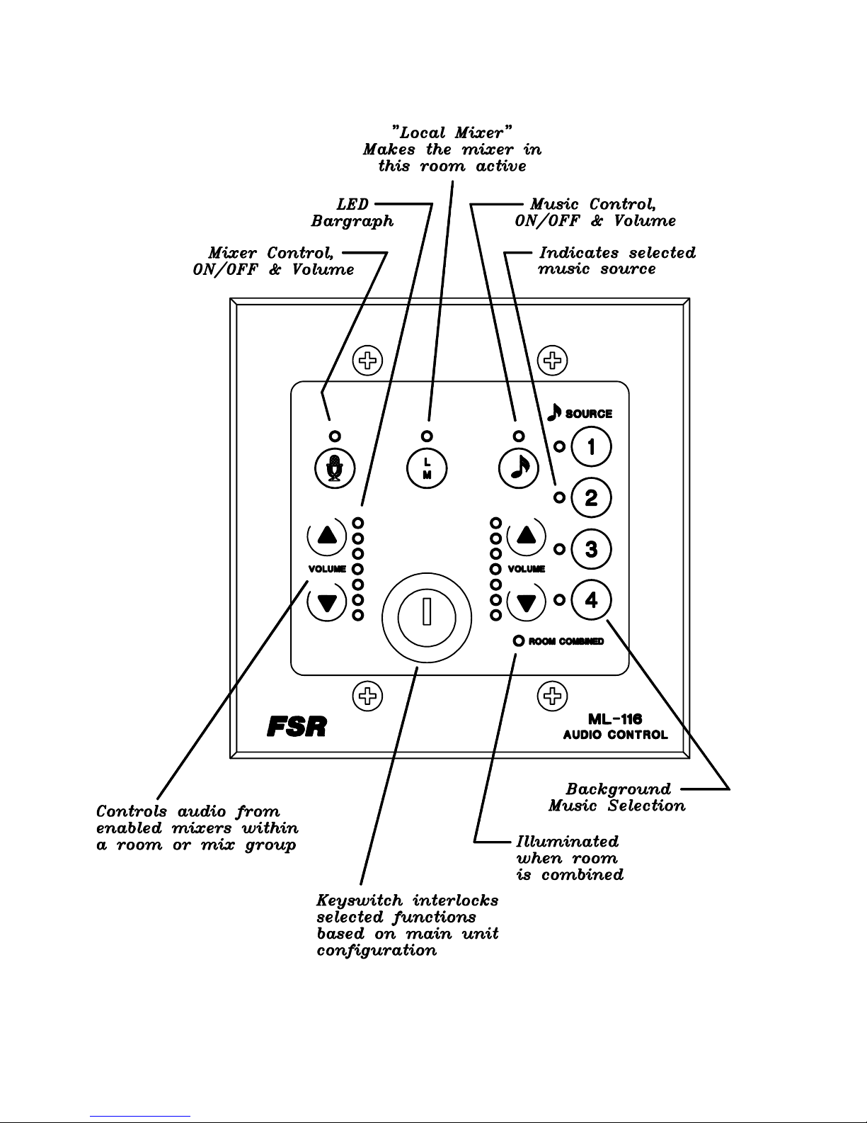
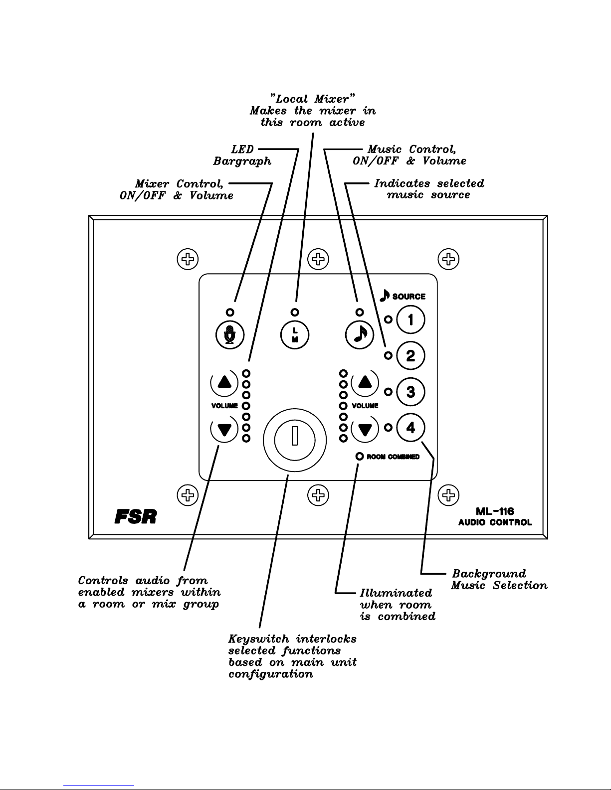
Wall Plates
Size: 6 1/4incheswide by 41/2incheshigh, approximately 2.5inchesdeep
Mounting: fitsstandard2 or 3 gangelectricalwallboxwith four or6screws
Switches: membrane
Connector: 5 pin connector
Cable: West Penn #3651 or 3751 (see page 13 for details)
Power Supply (PSA)
Size: 3 1/2inch high,6inchesdeep,10incheslong(approximately)
Mounting: rearrackrail
Inputpower: 105 to 132 VAC, 50/60 Hz, 100 watts
Output: +15volts,+25 volts, -25voltsnominal
Fuse: 2 amp
Switch: poweron/off (lightedrockerswitch)
Interconnect: 8 footcablesupplied,5conductorstranded
Indicators: three LEDindicators,onefor eachofthe unregulatedvoltages
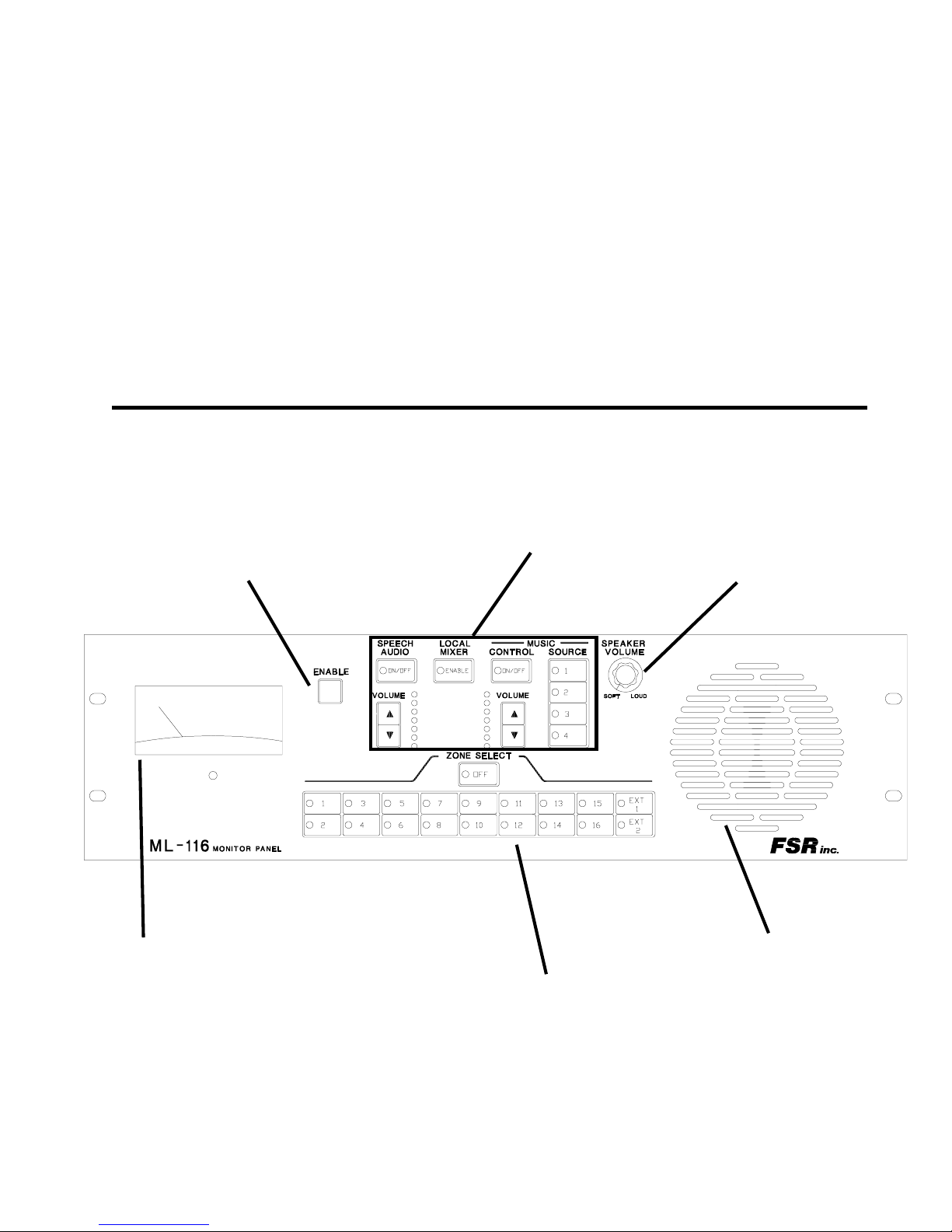
MON Monitor/VU Panel Assembly (optional)
Monitor/VUPanel
Input: 70Volt speakerlevel
Size: 19 incheswide, 5 1/4incheshigh(3RU),4 1/2 inchesdeepoverall
Mounting: standardrackrails
MonitorRelayCard(suppliedwiththe Monitor/VU card)
Size: 3 1/4incheswide, 9 1/2incheslong, 1 inchhigh,comesalready mounted ina
19inchFSRTRAC-BRAC
Mounting: rearrackrails
MLH Head Table Speaker Assembly (optional)
HeadTableBreakoutCard (HTBC)
Size: 3 1/4incheswide, 23/4incheslong, 1/2 inchhigh
Power: HT-PS supply provided
HeadTableRelay Card (HT-8)
Size: 3 1/4incheswide,7 1/4 inches long,1inchhigh,canhave up to fourofthese
cardspersystem
Mounting: rearrackrails,boththeHTBCandtheHTcardcomealreadymountedina19
inchFSRTRAC-BRAC
FM Facility Manager Control (optional)
FacilityManagers Panel (FM-INT)
Size: an enclosedbox 3 1/2incheswide,5inches long, 11/2incheshigh
Mounting: sitsonthe managers desk
Power: awall mountedpowersupply