Willy WS-8450 User manual

WS-8450 Bridge-Saw
Operation Manual

Contents
1. Safety and Health Precautions ...............................................................................................1
1.1 CAUTION.......................................................................................................................... 1
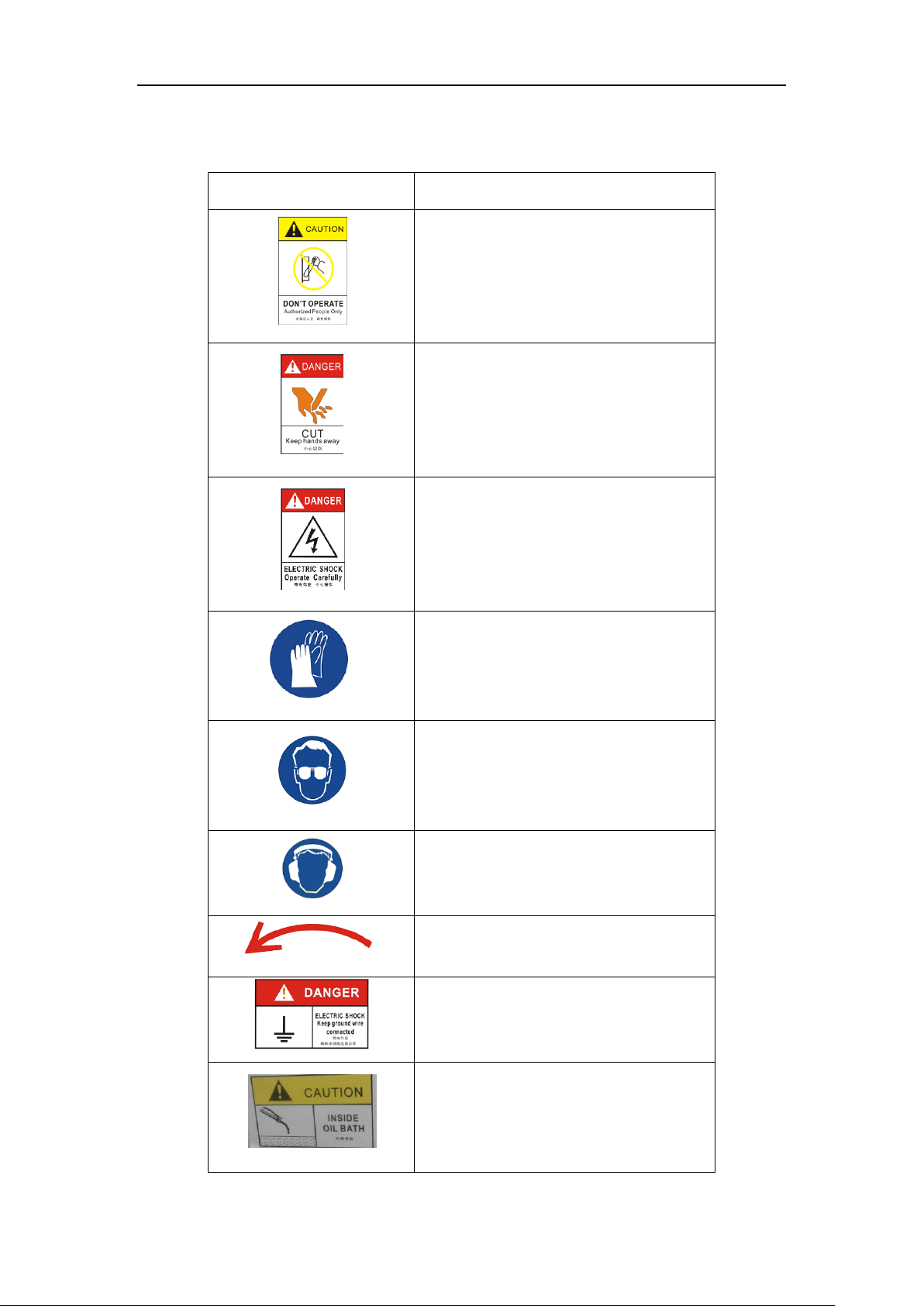
1.2 Graphic Symbols.............................................................................................................. 2
1.3 Technical Data ................................................................................................................. 3
2. Installation..............................................................................................................................4
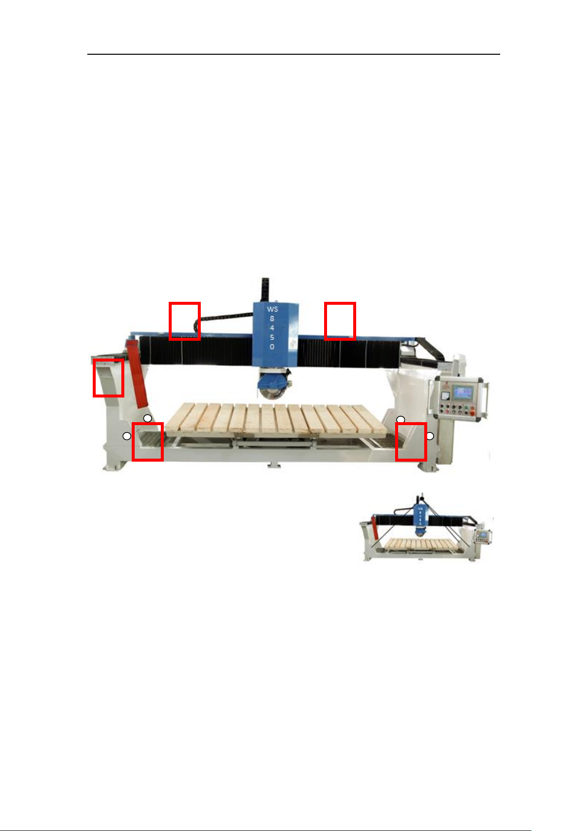
2.1 Lifting and Moving Machine............................................................................................ 4
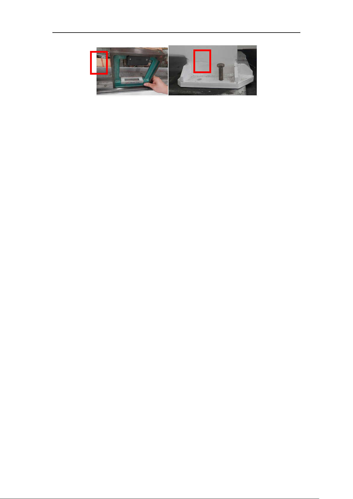
2.2 Machine Leveling............................................................................................................. 4
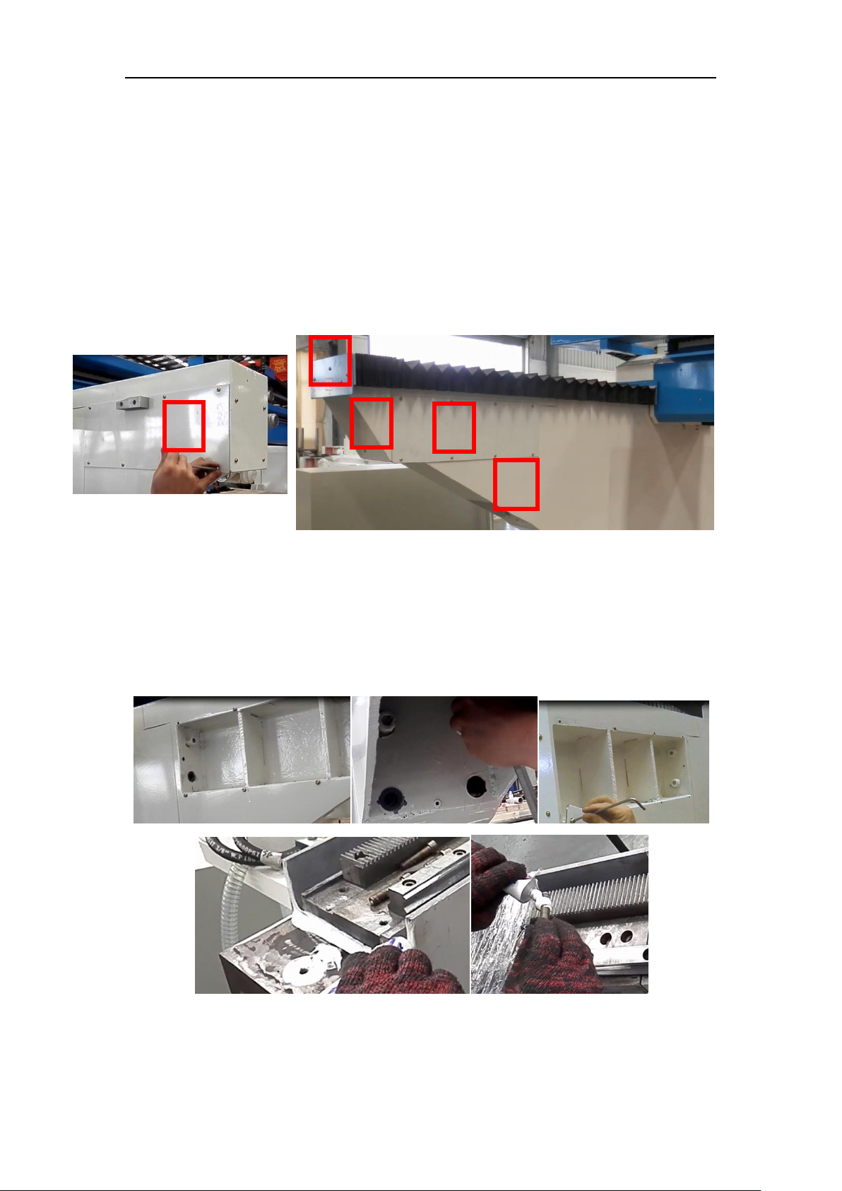
2.3 Bridge Installation............................................................................................................ 6
2.4 Lubrification.......................................................................Error! Bookmark not defined.
3. Operation ...............................................................................................................................9
3.1 Axis Reference ................................................................................................................. 9
3.2 Turning on the Machine .................................................................................................. 9
3.3 Panel.............................................................................................................................. 10
3.4 HMI ................................................................................................................................ 12
3.5 Example ......................................................................................................................... 19
4. Adjusts and Maintenance.................................................................................................... 30
4.1 Hydraulic Adjust. ........................................................................................................... 30
4.2 Maintenance.................................................................................................................. 31
5. Attachment.......................................................................................................................... 32
5.1 Parameter...................................................................................................................... 32
5.2 Input/Output ................................................................................................................. 33
5.3 Server Parameter........................................................................................................... 35
5.4 Hydraulic System ........................................................................................................... 36

1
1.Safety and Health Precautions
1.1 CAUTION
The instruction manual contains warnings clearly highlighted by symbols. These warnings call
your attention to particular situations that may be hazardous for your safety. Read the
warnings with greatest attention.
Use of the machine and access to it must be consented only to specialized operators.
The machine must not be used by an occasional operator, but by an operator who has
acquired a certain experience and training in the use of this machine. It is specified that
“OPERATOR”is defined as the person or persons assigned to install, run, adjust, service and
clean the machine.
The following personal protective devices are recommended during the installation, operation
and servicing of machine: safety glasses with, ear plugs or ear muffs, safety gloves, safety
shoes, safety overalls and breathing mask.
Any equipment which is not related with the current operation should be out of the operating
area.
When all the settings necessary to switched to another working condition, it must be carried
out by professional person.
This manual describes the application of the machine.
Keep this manual in a safe place.
Willy Industries reserves the right to make variations to the production and the manual.
Failure to comply with the safety prescriptions or the improper use of the machine may cause
damage to those articles in the operating area.
Keep hands or any other parts of your body away from moving element of the machine.
During the exploitation, the water may be splashed and the blades may be dangerous to
people.

2
1.2 Graphic Symbols
WARNING SIGN
SAFETY INSTRUCTIONS
Operate by authorized people only.
Risk of crushing one’s hands if this
operation is not performed in compliance
with safety regulations.
Risk of electric shock if operation is not
performed in compliance with safety
regulation.
Recommended use of safety work gloves
Recommended use of safety goggles
Recommended use of protective ear muffs.
Spindle rotating direction.
Keep ground wire connected.
Inside oil bath.

3
1.3 Technical Data
Willy WS-8450
Max. work piece length
3300
mm
Max. work piece width
2000
mm
Max. work piece height
100
mm
Blade diameter
400--450
mm
Max. spindle speed
2900
rpm
Blade rotate angle
0、90
degree
Blade tilt angle
0-90
degree
Table tilt angle
0-85
degree
Table rotate angle
0-360
degree
Power supply voltage
400
V AC
Power supply frequency
50
Hz
Spindle power
15
kw
Total power
23
kw
Overall L×D×H
5510×3260×2765
mm
Weight
≤13000
lb

4
2.Installation
2.1 Lifting and Moving the Machine
Check that the equipment and accessories used to lift the machine (belts, cables, hooks) are
capable of supporting the weight of the machine as indicated on the identification plate.
Bring the machine down onto the floor with the greatest care avoiding sudden drops and
hazardous jerks.
Never hook belts directly onto the mobile beam (1) or to the machine base (2), to avoid
irreparable damage to the structure. Use the four lugs (3) provided for lifting.
The lifting equipment should be inserted by skilled persons to avoid damaging the machine
and to prevent the load from sliding.
2.2 Machine Leveling
This machine does not need a foundation, but an industrial floor with a thickness of concrete
of at least 100mm must be provided.
It is necessary for the machine to be correctly leveled. Remove the protection covers on both
supporting shoulders of the mobile gantry. Place the spirit level (1) on the guide on the right side
support shoulder. Adjust the leveling screws located on the support feet (2) at the base of the
machine.
Repeat the same operations for the left side support shoulder.
1
1
2
3
3

5
1
2

6
2.3 Bridge installation
We remove some parts from both sides of bridge when shipping. The instructions bellow will
inform how to install these loose parts:
Shoulder extended part (1).
Protection cover connection part (2).
Metal sheet (3)(4).
Protection cover (5).
Important: The Y+ limit block is installed at metal sheet (3), so don’t initiate work on the
machine before installing this part.
2.3.1 Installation of shoulder extended part:
Install 3 locating pins (1) and 8 screws (2).
Add sealant on the surface (3) connected to the machine body, screw (5) and screw hole (4)
when installs.
1
1
1
3
2
2
2
2
2
2
2
5
4
2
5
4
1
2
3

7
2.3.2 Other parts.
We removed the following parts when shipping. You have to install them before using machine.
1) Encoder (1).
2) Pipeline (2).
3) Hydraulic (3).
4) Manual Grease (4).
5) Cable trough (5).
4
2
3
1
5

8
2.4 Lubrication
Both sides of bridge (1) and Beam (2) will need be lubricated in the oil bath. Oil level must be
higher than linear guide and rack. Usually it uses engine oil or rail oil. After machine has been
installed, please take dust cover off, then pour oil inside to lubricate the gear and guide of the X
axis and Z axis.
Add Semi-fluid grease on the grease pump. Grease is used to lubricate the guide of the Z axis
and one of the X axis guides.
2
1
Guide of Z axis
Guide of X axis

9
3.Operation
3.1 Axis reference
3.2 Turn on the machine
1. Turn on main power.
2. Turn on the emergency switch.
3. Press the ‘Start’switch.
Z+
Z-
X-
X+
Y+
Y-

10
3.3 Panel
Number
Picture
Name
Function
1
Touch screen
2
Ammeter
Voltmeter
Current of the spindle motor.
Voltage of main power
3
Table flip switch
Left: Turn up table.
Right: Turn down table
1
2
3
4
5
6
7
8
9
10
1
1
1
2
1
3
14

11
4
Table rotate switch
Left: rotate table anticlockwise.
Right: rotate table clockwise.
5
Joystick axis
motion XZ
X+, X-: Move X axis.
Z+,Z-: Move Z axis.
6
Joystick axis
motion Y
Move Y axis.
7
Spindle start
Start spindle.
8
Spindle stop
Stop spindle.
9
Laser
Turn laser on/off.
10
Power on switch
Turn on the power of the control
system.
11
Potentiometer 1
Adjust the feed rate of X axis and Z axis.
12
Potentiometer 2
Adjust the feed rate of Y axis.
13
Auto mode start
Automatic cutting starts.

12
14
Emergency stop
Turn off the power of PLC.
3.4 HMI
3.4.1 Settings
X axis cut Acc and Dec distance: Accelerate and decelerate distance at length direction when “cut
of X axis”. I is used when blade start to cut into stone.
Y axis cut Acc and Dec distance: Accelerate and decelerate distance at length direction when “cut
of Y axis”.
Blade thickness: set thickness of blade.
Spindle Acc time: Spindle accelerating time, Star circuit convert to delta when spindle start.
Select cutting process. The first type is cutting at single
direction (forward direction), the second type can cut at double directions.
Set the precision parameter. After press the command, system prompts you to
enter the user name and password. The user name is ”admin”, password is “hl2223”. Press
“Parameter”again, the screen should display all the parameters of machine page by page. Detail
massage of “precision parameters”is explained in attachment.
Build up machine zero. Machine researches the specified limit switch in slow
speed after this command be triggered.

13
Lubricate machine manually.
3.4.2 Auto
Cut of X axis: Blade cut along X axis when head at 0 degree.
Cut of Y axis: Blade cut along Y axis when head at 90 degrees.
Width: The distance between two adjacent cutting.
Pieces: Specify number of pieces to be cut and width.
X Axis cutting length: Set cutting length of X axis.
Y Axis cutting length: Set cutting length of X axis.
Z- Limit Location Value: Set Z value of wood top surface. Press to auto measure.
This parameter is the virtual of Z- limit switch. Set the data to a large negative
value before moving blade to top of wood.
This parameter is saved on the system, please set it when you use the machine
first time. Adjust this value when diameter of blade changes.
Clear all the data on the table.
Rotate head to 0 degree.
Rotate head to 90 degrees.
Set current position as origin of “cut of X axis”.
Set current position as origin of “cut of Y axis”.
Choose single or multi feed at depth direction (Z axis).
Indicate lamp of spindle speed. The red lamp will turn to green when

14
speed reaches a normal value. Auto mode can’t be triggered until this lamp turns to green.
Machine will back to zero (initial) position when this command is triggered.
3.4.3 Manual
Function of manual mode is to cut single line.
Press X+(X-), machine executes X direction single cut when head at 0 degree. Press Y+(Y-),
machine executes Y direction single cut when head at 90 degree. The value which “Distance”
specifies is cutting length.
Press Y+(Y-) when head at 0 degree, machine move along Y axis without Z feed. Press X+(X-)
when head at 90 degree, machine move along X axis without Z feed.
Distance: Specify single cutting length.
Z- Limit Location Value: Set Z value of wood top surface. Press to auto measure.
This parameter is the virtual of Z- limit switch. Set the data to a large negative
value before moving blade to top of wood.
This parameter is saved on the system, please set it when you use the machine
first time. Adjust this value when diameter of blade changes.
: Specify move direction.
: Machine return to zero position.
: Rotate head to 0 degree.

15
: Rotate head to 90 degrees.

16
3.4.4 Profiling
Profiling function is use to process all kinds of line or abnormal stone. Please make the
profiling model before processing. Blade cuts along the model when blade is at 90 degrees.
Parameters:
Profiling Length(Y): Specify the profiling length at Y axis;
Profile total length(X2): Specify profiling width at X axis.
Profile Length(X1): Specify each feed distance at X axis.
Each Feed Depth: Specify each feed depth at Z axis.
Commands:
:This command is use to Open or Cancel profiling function.
:This command is use to select Roughing or Finishing profiling.

17
3.4.5 Table
Clear “Table current position”to 0 when table at 0 position.
Start to rotate the table to direction which “Table rotation (deg)”specified.
This function is enable in JOG Rotate mode.
Specify table rotate mode, JOG or Auto.
Jog mode: Table would rotate to the specify direction.
Auto mode: Table would stop each 45 degree.
Stop table rotate.
Table rotation (Degree): Specify the destination direction of table.
Table positioning accuracy: Setting positioning accuracy of table.
Table locate Dec distance: Setting decelerate distance when table rotate.
Table current position: Display current position of table.

18
3.4.6 Joystick
Joystick axis motion XZ.
Joystick axis motion Y.
We design special function of joystick axis motion when automatic cycle is running.
System finish current cutting when you press Z+ direction, then machine moves to next
step to continue auto cycle.
This is useful if you set cutting length larger than product size.
Cut of X axis: System finish current cutting when you press X- direction, then machine
returns to origin point.
Cut of Y axis: System finish current cutting when you press Y+ direction, then machine
returns to origin point.
This function is useful if stone broken when cutting.
Table of contents