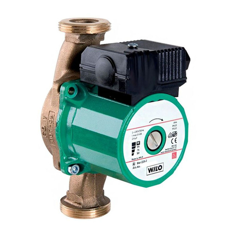
Wilo Yonos Para RS 25/6 Guide

MANUALE INSTALLAZIONE ED USO
IT
INSTALLATION AND USE MANUAL
GB
FR
MANUEL D’INSTALLATION ET D’UTILISATION
DE
INSTALLATIONS - UND BETRIEBSANLEITUNG INNENGERÄT
MANUAL DE INSTALACION Y USO
ES
РУКОВОДСТВО ПО УСТАНОВКЕ ПО ЭКСПЛУАТАЦИИ
RU
0
20
60
80

2
ITIT GBGB
INDICE / INDEX
ITIT
Vi ringraziamo per la fiducia concessaci nell’acquisto di questo prodotto. Vi
invitiamo a leggere attentamente questo manuale dove sono riportate le
caratteristiche tecniche e tutte le informazioni utili per ottenere un corretto
funzionamento. I dati contenuti in questa pubblicazione possono, per una
riscontrata esigenza tecnica e/o commerciale, subire delle modifiche in
qualsiasi momento e senza preavviso alcuno; pertanto non ci riteniamo
responsabili di eventuali errori o inesattezze in essa contenute.
Attenzione! Conservare i manuali in luogo asciutto per evitare il deteriora-
mento, per eventuali riferimenti futuri
GBGB
Thanks you for the trust you have shown by purchasing this produtc.Carefully
read this manual which contains the specifications and all the information
useful for the correct functioning. The information contained in this publica-
tion may be subject to changes at any time and without any notice what-
soever for technical and/or commercial reasons as they arise; therefore, we
cannot be held responsible for any errors or imprecisions contained herein.
Warning! Keep these manuals in a dry place avoiding in this way to spoil
them.
1. DESCRIPTION............................... 3
1.1 Construction
1.2 Technical data
1.3 Hydraulic diagram of thermostatic regulation units and
electronic circulator
2. INSTALLATION AND TESTING ......... 6
2.1 Installing the units
2.2 Installing the thermostatic head with immersion probe for thermo-
static regulation
2.3 Limitation of the maximum temperature
2.4 Testing and filling
3. BALANCING AND SETTING
THE SYSTEM ............................... 7
3.1 Dimensional example
3.2 Adjusting the project temperature
4. REPLACING THE COMPONENTS ..... 10
4.1 Replacing the servomotor
4.2 Replacement thermostatic head
5. WILO YONOS PARA CIRCULATOR.... 11
5.1 Commissioning
5.2 Troubleshooting
5.3 Declaration of conformity
6. SAFETY THERMOSTAT ................. 14
6.1 Adjustable thermostat housing
7. WIRING DIAGRAMS .................... 16
7. DECLARATION OF CONFORMITY ... 49
1. DESCRIZIONE ............................... 3
1.1 Costruzione
1.2 Dati tecnici
1.3 Schema idraulico dei gruppi con regolazione a punto fisso e circo-
latore elettronico
2. INSTALLAZIONE E COLLAUDO ........ 5
2.1 Installazione dei gruppi
2.2 Installazione della testa termostatica con sonda ad
immersione per la regolazione a punto fisso
2.3 Limitazione della temperatura massima
2.4 Collaudo e riempimento
3. BILANCIAMENTO E REGOLAZIONE
DELL’IMPIANTO............................ 7
3.1 Esempio di dimensionamento
3.2 Regolazione della temperatura di progetto
4. SOSTITUZIONE DEI COMPONENTI... 10
4.1 Sostituzione del circolatore
4.2 Sostituzione testa termostatica
5. CIRCOLATORE WILO YONOS PARA .. 11
5.1 Messa in servizio
5.2 Guasti, causa e rimedi
5.3 Dichiarazione di conformità
6.TERMOSTATO DI SICUREZZA ......... 14
6.1 Termostato in custodia regolabile
7. SCHEMI ELETTRICI ...................... 16
DICHIARAZIONE DI CONFORMITÀ ..... 49

3
ITIT GBGB
1. DESCRIZIONE
/
DESCRIPTION
1.1 Costruzione
Nr. 1 valvola di miscelazione con filettatura M30x1,5 predisposta per
installazione di una testa termostatica con sonda ad immersione da 20
a 65 °C o di un servomotore elettrico (non fornito in dotazione);
Nr. 1 valvola di taratura e by-pass;
Nr. 1 valvola di sfogo aria ½” (automatica);
Nr. 1 testa termostatica con sonda ad immersione regolabile da 20 a 65
°C limitata a 50 °C;
Nr. 1 valvola di non ritorno;
Nr. 1 termometro di controllo da 0 a 80 °C;
Nr. 1 alloggiamento per sonda di temperatura di mandata;
Nr. 1 Alloggiamento per sonda termostato di sicurezza
Nr. 1 circolatore elettronico Wilo Yonos PARA RS 25/6 (dove previsto)
Nr. 1 scatola con termostato di sicurezza per cablaggio circolatore bassa
temperatura (ove previsto)
Predisposizione per creazione foro per fissaggio a muro con vite e tassello
(non forniti)
Nr. 1 kit valvole a sfera (non fornito in dotazione);
1.1 Construction
No. 1 mixing valve with M30x1.5 thread designed for the installation of a
thermostatic head with an immersion probe from 20 to 65°C or an electric
servomotor (not supplied);
Nr. 1 calibration valve and by-pass;
Nr. 1 ½”
air vent valve
(automatic);
Nr. 1
thermostatic head with immersion probe setting from 20 to 65 °C
limited to 50 °C
;
Nr. 1 non-return valve;
Nr. 1
thermometer 0 - 80 °C scale
;
Nr. 1
housing for flow temperature probe
;
Nr. 1
housing for safety thermostat probe;
Nr. 1
electronic circulator
Wilo Yonos PARA RS 25/6 (
where applicable
)
;
Nr. 1 box with safety thermostat for low temperature circulator wiring
(
where applicable
)
;
Predispositions for creating a hole for wall mounting by means of screw
and dowel (
not supplied
);
Nr. 1
ball valve set
(
not supplied
);
Fig. A
4
1
9
5
10
6
3
8
7
11
12
2
11
192
29
85,7
26
G1”
G1”
G1”
210
382
G1”
50 G1”
10
G1”
0
20
60
80
Ritorno caldaia
Boiler return Mandata caldaia
Boiler Flow

4
ITIT GBGB
1. DESCRIZIONE
/
DESCRIPTION
1.2 Dati tecnici
Temperatura massima circuito primario: 90 °C
Pressione massima: 6 bar
ΔP max circuito primario: 1 bar
Campo di regolazione secondario:
(regol. punto fisso) 20÷65 °C
Potenza termica scambiabile (ΔT 7°C, ΔP utile 0,25 bar)
Regolazione punto fisso: 10 kW by-pass pos. 0
Regolazione punto fisso: 12.5 kW by-pass pos. 5
Perdite di carico valvola miscelatrice Kv 3
Perdite di carico con valvola by-pass aperta Kvmax 4,8
Scala termometro: 0÷80 °C
Filettature ingresso gruppo di miscelazione: G 1” F
Filettatura bocchettoni G 1” M
Attacchi circolatore
G 1”1/2 - interasse 130 mm
1.3 Schema idraulico dei gruppi con regolazione a punto fisso e circolatore elettronico
Hydraulic diagram of thermostatic regulation units and electronic circulator
Qip
Qby-pass
Tip
Tc
Tr
Tr
1.2 Technical data
Primary circuit maximum temperature : 90 °C
Maximum pressure: 6 bar
Primary circuit max ΔP: 1 bar
Secondary control range:
(thermostatic regulation) 20÷65 °C
Heating capacity that can be exchanged (ΔT 7°C, ΔP available 0.25 bar)
Thermostatic regulation 10 kW by-pass pos. 0
Thermostatic regulation 12.5 kW by-pass pos. 5
Mixing valve pressure drops Kv 3
Pressure drops with open bypass valve Kvmax 4.8
Thermometer scale: 0÷80 °C
Mixing unit inlet threads: G 1” F
Connections Thread: G 1” M
Circulator connections: pipe union 1”1/2 - takeoffs 130 mm

5
ITIT
2. INSTALLAZIONE E COLLAUDO
2.1 Installazione dei gruppi
Il gruppo di miscelazione può essere installato direttamente a muro,
collegato ai collettori di distribuzione o fissato con idonei tasselli e viti
(da scegliere in funzione del tipo di parete) da applicare in corrispondenza
dei fori (rif. fig. A)da praticare sui corpi costituenti il gruppo.
Il gruppo può essere installato anche in cassetta metallica solo se colle-
gato ai collettori di distribuzione, in questo caso prevedere uno spessore
di incasso minimo di 120 mm.
2.2 Installazione della testa termostatica con
sonda ad immersione per la regolazione a
punto fisso
Per facilitare il montaggio, impostare sulla testa termostatica il valore
massimo, ricordandosi di riportarla alla temperatura di progetto per
l’impianto a pavimento.
Successivamente, inserire la sonda nel pozzetto (rif. Fig.A).
2.3. Limitazione della temperatura massima
1. Sfilare il fermo rosso (rif. fig. B)
2. Impostare la temperatura massima desiderata.
3. Individuare il pallino nero stampato (rif. fig. B)
tra le temperature 70 e 20 °C.
4. Infilare il fermo (Rif. Fig. C) nel primo alloggiamento che precede il
pallino nero (Fig. C).
Ad operazione avvenuta, la manopola non potrà essere posizionata su
temperature maggiori a quella desiderata.
Fig. CFig. B
PALLINO NERO
ROSSO
2070
Fig. D
NO
Fig. E
2.5 Collaudo e riempimento
– Effettuare la prova di collaudo del gruppo mantenendo chiusi le valvole
e i detentori presenti sui collettori di distribuzione.
– Successivamente, al termine del collaudo del gruppo, ridurre la pressio-
ne all’interno dei collettori mediante i rubinetti di carico e scarico
– A questo punto procedere al riempimento di ogni singolo circuito
separatamente, aprendo la valvola e il detentore della singola via fino
a completa espulsione dell’aria.
– Per un corretto riempimento, collegare l’acquedotto al rubinetto nel col-
lettore di mandata nella parte alta, ed un tubo di gomma per lo scarico
dell’aria nel collettore di ritorno, all’interno del gruppo di miscelazione
è presente una valvola di non ritorno che previene la circolazione in
contro flusso all’interno del gruppo facilitando l’espulsione dell’aria
all’interno dei circuiti (fig. D e E).
Ok
Valvola di non ritorno

6
GBGB
2. INSTALLATION AND TESTING
2.4 Testing and filling
– Carry out the hydraulic test on the unit, close the valves and the
lockshields on the distribution manifold.
– At the end of the test, reduce the pressure inside manifolds using
the drain valves.
– Now fill each circuit individually by opening the valve and lockshield
of the single way until all the air comes out.
– For a correct filling connect the water supply to the drain valve in the
flow manifold on the top and a tube to the drainvalve in the return
collector. Inside the mixing unit there is a check valve that prevents
backflow circulation inside the unit, thereby making it easier to expel
the air inside the circuits (fig. D and E).
2.1 Installing the unit
The mixing unit can be installed directly on the wall connected to distribu-
tion manifold or fixed by means of suitable plugs and screws (depending
on the kind of wall) to be applied in correspondence of the holes (ref.
fig.A) to be drilled on bodies constituting the unit.
The unit can also be installed in a metal cabinet if it is connected to the
distribution manifolds, in this case provide a minimum depth of 120 mm.
2.2 Installation of thermostatic head with immer-
sion probe for fixed regulation immersion
probe for thermostatic regulation
To make it easier to assemble, set the maximum value on the thermostatic
head. Bear in mind you need to set it back to the temperature envisioned
in the project for the floor-mounted system.
Then insert the probe in the well (ref. Fig. A).
2.3 Limitation of the maximum temperature
1. Remove the red latch (rif. fig. B).
2. Set the desired maximum temperature.
3. Locate the black dot printed (rif. fig. B) between the temperatures
70 and 20 ° C.
4. Insert the latch (rif. fig. C) in the first slot which precedes the black
dot.
After successful operation, the knob can not be positioned on higher
temperatures than desired.
Fig. CFig. B
RED
2070
BLACK BALL
Fig. D
NO
Fig. E
Ok
Check valve

7
ITIT GBGB
3. BILANCIAMENTO E REGOLAZIONE DELL’IMPIANTO
3. BALANCING AND SETTING THE SYSTEM
3.1 Esempio di dimensionamento
3.1.1 Regolazione a punto fisso
Dati di progetto:
P= potenza da fornire all’impianto a pavimento = 6000W
Tip = temperatura di mandata impianto a pavimento = 40°C
Tc = temperatura acqua proveniente da caldaia = 70°C
ΔTip = salto termico di progetto impianto a pavimento = 5°C
Tr = temperatura di ritorno impianto a pavimento = Tip –ΔTip = 40 – 5
= 35°C
Qip = portata impianto a pavimento = (P[W] x 0,86) / (ΔTip) = (6000 x
0,86) / 5 = 1032 l/h
ΔP valv = perdita di carico valvola di regolazione
Dal diagramma sottostante alla portata di 1032 l/h corrispondono
6 curve diverse corrispondenti alle diverse regolazioni del by-pass
(rif. fig. A): minore è l’apertura del by-pass minori sono i tempi di
reazione della valvola miscelatrice alle variazioni di temperatura e più
rapidamente viene raggiunta la temperatura di mandata richiesta, al
contrario l’apertura del by-pass riduce le perdite aumentando la portata
all’impianto e riducendo, al contempo, i pendolamenti della temperatura
di mandata dovuti all’apertura-chiusura delle varie zone in cui è suddiviso
l’impianto di riscaldamento.
Diagramma Circolatore Yonos Para
Yonos Para Circulator Diagram
3.1 Dimensional example
3.1.1 Thermostatic regulation
Project data:
P= capacity to provide to the floor-mounted system = 6000W
Tip = delivery temperature of the floor system = 40°C
Tc = temperature of the water coming from the boiler = 70°C
ΔTip = project temperature drop of the floor-mounted system = 5°C
Tr = floor-mounted system return temperature = Tip –ΔTip =
40 – 5 = 35°C
Qip = floor-mounted system flow-rate = (P[W] x 0,86) / (ΔTip) =
(6000 x 0,86) / 5 = 1032 l/h
ΔP valv = control valve pressure drop
From the diagram underneath the 1032 l/h flow rate, there are 6 different
curves that correspond to the various bypass adjustments (ref. fig. A):
the less the bypass opens, the shorter the response time of the mixing
valve to the temperature variations and the requested delivery tempera-
ture is reached in a shorter amount of time. Conversely, the opening of
the bypass reduces the drops by increasing the system’s flow-rate and
simultaneously reducing the flow temperature oscillations due to the
opening-closure of the various areas the heating system is divided into.
Perdite carico gruppo miscelazione
Mixing unit pressure drops
100
1000
10
0
00010001001
0 Kv=3
1 Kv=3,4
2 Kv=3,8
3 Kv=4,2
4 Kv=4,5
4 Kv=4,5
5 Kv=4,8
0
Δp [mbar]
Q [l/h]
Δp-c
max.
Δp Costante
1
2
3
4
5
6
0,5 1,0 1,5 2,0 2,5
03,0
Q [m3/h]
H [m]

8
1. DESCRIZIONE DEI COMPONENTI ITIT GBGB
Impostando il bypass alla posizione 1 alla portata di 1032 l/h corrisponde
una perdita di carico di 90 mbar (0,09 bar).
Supposto ΔP pav = perdita di carico impianto a pavimento = 0,25 bar
regolare la potenza del circolatore Wilo Yonos PARA in modo da garantire
una portata di 1032 l/h (1,03 m3/h) e una prevalenza H = ΔP valv + ΔPpav
= 0,09 + 0,25 = 0,34 bar (≅3,4 m CA).
8
3. BILANCIAMENTO E REGOLAZIONE DELL’IMPIANTO
3. BALANCING AND SETTING THE SYSTEM
By setting the bypass to 1, a 1032 l/h flow rate corresponds to a 90 mbar
pressure drop (0.09 bar).
Assuming that ΔP pav = floor-mounted system pressure drop = 0.25 bar,
set the capacity of the Wilo Yonos PARA circulator in order to sure a flow
rate of 1032 l/h (1.03 m3/h) and a head H = ΔP valv + ΔPpav = 0.09 + 0.25
= 0.34 bar (≅3.4 m MWC).
Qip
Qby-pass
Tip
Tc
Tr
Tr
Si riportano di seguito alcune tabelle contenenti i dati di impianti, scelti
sulla base del carico termico richiesto.
Si consiglia quindi di utilizzare la tabella o le formule per una prima
impostazione, e di verificare mediante i termometri che le temperature di
progetto del fluido vengano effettivamente raggiunte.
Per aumentare il ΔT dei circuiti a pavimento è sufficiente ridurre la portata
di by-pass.
Here below are some tables that report the data for systems selected based
on the requested heating capacity.
Therefore, first use the table or formulas to carry out the setting and then
use the thermometers to make sure the project temperatures of the fluid
are actually reached.
To increase the ΔT of the floor circuits, just reduce the bypass flow rate.
ΔTip = 10 °C T caldaia = 70 °C Tip = 45 °C ΔPip = 0,25 bar
Potenza (W) Regolazione
circolatore
Regolazione
by-pass
18000 massima 5
17000 massima 3 - 4
16000 massima 2
15000 massima 1
14000 massima 0
13000 media 5
12000 media 4
11000 media 2 - 3
10000 media 1
ΔTip = 5 °C T caldaia = 70 °C Tip = 45 °C ΔPip = 0,25 bar
9000 massima 5
8000 massima 2 - 3
7000 massima 0
6000 media 5
5000 media 2 - 3
4000 media 0
ΔTip = 10 °C T Boiler = 70 °C Tip = 45 °C ΔPip = 0,25 bar
Capacity (W) Circulator
setting
Bypass
setting
18000 maximum 5
17000 maximum 3 - 4
16000 maximum 2
15000 maximum 1
14000 maximum 0
13000 average 5
12000 average 4
11000 average 2 - 3
10000 average 1
ΔTip = 5 °C T Boiler = 70 °C Tip = 45 °C ΔPip = 0,25 bar
9000 maximum 5
8000 maximum 2 - 3
7000 maximum 0
6000 average 5
5000 average 2 - 3
4000 average 0

9
1. DESCRIZIONE DEI COMPONENTI ITIT GBGB
3. BILANCIAMENTO E REGOLAZIONE DELL’IMPIANTO
Per impostare la temperatura di progetto si seguano le seguenti indicazioni:
1. Ruotare la manopola della testa termostatica, impostando il valore della
temperatura di mandata.
2. Attendere che l’impianto vada a regime e controllare che la temperatura
di mandata ed il salto termico fra mandata e ritorno dell’impianto a
pavimento siano quelli di progetto.
3. Se necessario, agire sulla regolazione del by-pass di taratura nel modo
seguente:
– Salto termico troppo elevato.
La portata è insufficiente , aprire la valvola del by-pass taratura progres-
sivamente fino a raggiungere il salto termico di progetto.
– Temperatura di mandata inferiore al valore impostato.
Chiudere la valvola del by-pass di taratura progressivamente in modo
tale da creare una pressione differenziale che permetta l’iniezione di
fluido ad alta temperatura proveniente dalla caldaia.
Messa in servizio - Verifica problemi
– I circuiti dell’impianto a pavimento devono essere aperti.
– Eventuali teste elettrotermiche devono essere portate in posizione di
apertura.
– Eventuali valvole di sovrapressione devono essere tarate in funzione
delle caratteristiche del circolatore
3.2 Regolazione della temperatura di progetto
3.2.1 Regolazione punto fisso con testa termosta-
tica
La temperatura dell’acqua di alimentazione dell’impianto a pavimento viene
fissata sulla testa termostatica (rif. n° Fig. A), tarabile da 20 a 65 °C, e
mantenuta costante dall’azione della stessa sulla valvola.
L’elemento termostatico della testa è collegato tramite un capillare alla
sonda ad immersione.
Attenzione
Il riscaldamento dell’impianto a pavimento può avvenire solo dopo
la maturazione del massetto (minimo 28 giorni nel caso di massetti
cementizi).
Prima della posa della pavimentazione è necessario avviare l’im-
pianto impostando una temperatura dell’acqua pari a 25 °C, da
mantenere per 3 giorni.
Successivamente aumentare di 5 °C ogni 3 giorni, fino a raggiunge-
re 50 °C da mantenere per almeno 4 giorni.
3.2 Adjusting the project temperature
3.2.1 Thermostatic regulation with thermostatic
head
The delivery water temperature of the floor-mounted system is set on the
thermostatic head (ref. no. Fig. A), which can be set to from 20 to 65°C
and kept steady thanks to the action of the valve itself.
The head’s thermostatic element is connected to the immersion probe
through a capillary.
Warning
The floor-mounted system can be heated up only after the screed’s
curing (at least 28 days for cement screeds).
Before laying the flooring, you need to start the system by setting
the water temperature to 25°C for 3 days.
Then, increase it by 5°C every 3 days, until you reach 50°C and keep
this temperature for at least 4 days.
Proceed as follows to set the project temperature:
1. Turn the knob of the thermostatic head, thereby setting the value of the
delivery temperature.
2. Wait for the system to be fully activated and make sure the delivery
temperature and the temperature drop between the delivery and return
line of the floor-mounted system are in line with those reported in the
project.
3. If necessary, proceed as follows to adjust the calibration bypass:
– Excessively high temperature drop.
Insufficient flow rate, gradually open the calibration by-pass valve until
you reach the project’s temperature drop.
– Delivery temperature below the set value.
Gradually close the calibration bypass valve in order to create a
differential pressure to inject the hot fluid coming from the boiler.
Activation - Troubleshooting
– The circuits of the floor-mounted system must be open.
– Any electrothermal heads must be set to the open position.
– Any overpressure valves must be calibrated in related to the features
of the circulator

10
ITIT GBGB
4. SOSTITUZIONE DEI COMPONENTI
4. REPLACING THE COMPONENTS
4.2 Sostituzione della testa termostatica
Per sostituire la testa termostatica, seguire la seguente procedura:
– estrarre la sonda dal pozzetto;
– svitare la testa termostatica e sostituirla;
– inserire la sonda nel pozzetto.
Per facilitare il montaggio, impostare sulla testa termostatica il valore
massimo, ricordandosi di riportarla alla temperatura di progetto per l’im-
pianto a pavimento.
10
Per eseguire la sostituzione del circolatore è necessario:
1. procedere alla chiusura delle valvole di intercettazione a monte (ref.
fig. G) ed a valle (se presenti) del gruppo di miscelazione
2. Svuotare il collettore di ritorno tramite la valvola di scarico (rif. fig. G);
3. togliere l’alimentazione elettrica;
4. allentare i bocchettoni;
5. scollegare il cavo di alimentazione;
6. rimuovere il circolatore e sostituirlo con quello nuovo;
7. ricollegare il cavo di alimentazione del circolatore secondo le
indicazioni riportate sul foglio allegato al circolatore stesso;
8. stringere i bocchettoni;
9. ripristinare l’alimentazione elettrica e riaprire le valvole a sfera ed i
detentori/misuratori dei collettori di distribuzione se installati.
Nota. In caso di sostituzione del circolatore è conveniente sostituire solo il
gruppo motore più girante, lasciando montato il corpo idraulico.
Proceed as follows to replace the circulator:
1. close the (ref. fig. G) upstream and downstream ball valves (if any)
of the mixing unit;
2. Empty the return manifold via the drain valve (rif. fig. G);
3. power off the equipment;
4. loosen the pipe joints;
5. disconnect the power cable;
6. take out the circulator and replace it with the new one;
7. re-connect the circulator’s power cable by following the directions
reported on the leaflet enclosed with the circulator itself;
8. tighten the pipe joints;
9. power on the equipment again and open the ball valves and lock-
shields/meters of the distribution collectors if installed.
Note If you are replacing the circulator, it is best to only replace the
motor unit plus the impeller and leave the hydraulic body in place.
4.2 Replacing the thermostatic head
Proceed as follows to replace the thermostatic head:
– take out the probe from the well;
– unscrew the thermostatic head and replace it;
– insert the probe in the well.
To make it easier to assemble, set the maximum value on the thermostatic
head. Bear in mind you need to set it back to the temperature envisioned
in the project for the floor-mounted system.
2
2
1
1
Fig. G
4.1 Sostituzione del circolatore 4.1 Replacing the circulator

11
ITIT GBGB
5. CIRCOLATORE WILO YONOS PARA
5. WILO YONOS PARA CIRCULATOR
11
Circolatore Wilo Yonos Para RS 25/6
Attacchi - interasse: G1”1/2 - 130 mm.
Velocità di rotazione: 800÷4250 rpm.
Fluidi utilizzabili
Acqua di raffreddamento e di riscaldamento.
Acqua e glicole: max 1:1
Prevalenza massima: 6.2 m
Portata massima: 3.3 m3/h
Temperatura max acqua: 95 °C (a temperature ambiente di 57 °C)
Temperatura max acqua: 90 °C (a temperature ambiente di 59 °C)
Temperatura max acqua: 70 °C (a temperature ambiente di 70 °C)
Collegamento elettrico 1~230 V, 50/60 Hz
Classe di protezione IPX 4D, di isolamento F
Potenza nominale motore: 37 W
Consumo di energia da 1~230 V: 3÷45 W
Corrente assorbita a 1~230V: 0.03 ÷0.44 A
Classe energetica: A
Wilo Yonos Para RS 25/6 circulator
Connections - takeoffs G1”1/2 - 130 mm
Rotation speed: 800-4250 rpm.
Fluids that can be used
Cooling and heating water.
Water and glycol: max 1:1
Maximum head: 6.2 m
Maximum flow rate: 3.3 m3/h
Max water temperature: 95 °C (with an ambient temperature of 57 °C)
Max water temperature: 90°C (with an ambient temperature of 59 °C)
Max water temperature: 70 °C (with an ambient temperature of 70 °C)
Electrical connection 1~230 V, 50/60 Hz
Protection class IPX 4D, insulation class F
Nominal motor power: 37 W
Energy consumption from 1~230 V: 3-45 W
Current consumption at 1~230V: 0.03 -0.44 A
Energy rating: A
Pericolo di ustioni!
A seconda della temperatura di esercizio del fluido circo-
lante nell’impianto, il circolatore può diventare molto caldo;
vi è quindi pericolo di ustione nel caso di contatto con il
circolatore.
Riempimento e sfiato.
Riempire e sfiatare correttamente l’impianto; uno sfiato del vano rotore
avviene di regola automaticamente già dopo un breve tempo di funziona-
mento. Nel caso però fosse necessaria un’aerazione diretta del vano rotore
è possibile avviare la routine di aerazione.
A tale scopo selezionare il simbolo per l’aerazione ruotando il selettore
rosso sul simbolo indicato di seguito.
air
La durata della routine di aerazione è di 10 minuti e può provocare rumore.
Durante questo periodo il circolatore opera alternativamente tra la minima
e la massima velocità. Al termine della routine impostare la modalità pre-
scelta ruotando il selettore.
Impostazione del modo di regolazione.
Selezionare il simbolo del modo di regolazione ruotando il selettore rosso.
Il valore della pressione differenziale generata dal circolatore aumenta,
nel campo di portata consentito, tra il 50% e il 100% rispetto al valore
impostato con il selettore rosso.
5.1 Messa in servizio
Burn hazard!
The circulator can become very hot, depending on the oper-
ating temperature of the circulating fluid; this results in burn
hazards upon contact with the circulator.
Filling and bleeding the system.
Fill and bleed the system completely. The rotor compartment is usually al-
ready emptied automatically after it has been operating for a short amount
of time. However, if it is necessary to ventilate the rotor compartment di-
rectly, it is possible to start the ventilation procedure.
Select the ventilation symbol by turning the red selector on the symbol
indicated here below.
air
The ventilation process lasts for 10 minutes and can generate noise. Dur-
ing this period of time the circulator operates alternatively between the
minimum and maximum speed. At the end of the process, set the selected
mode by turning the selector.
Setting the control mode.
Select the symbol of the control mode by turning the red selector.
The value of the differential pressure generated by the circulator increases,
in the field indicating the allowed flow rate, from 50% to 100% in relation
to the value set with the red selector.
5.1 Commissioning

12
ITIT GBGB
5. CIRCOLATORE WILO YONOS PARA
5. WILO YONOS PARA CIRCULATOR
Questa regolazione è particolarmen-
te adatta per impianti di riscalda-
mento con radiatori perché riduce
il rumore dovuto al flusso d’acqua
sulle valvole termostatiche.
DIFFERENZA DI PRESSIONE COSTANTE “Δp-c”
La pressione differenziale genera-
ta dal circolatore viene mantenuta
costante (sul valore impostato con il
selettore rosso) all’interno del campo
di portata consentito, fino alla portata
massima.
Si consiglia questa regolazione nei i
sistemi di riscaldamento a pavimento
o nei sistemi di riscaldamento vecchi
con tubazioni di grandi dimensioni.
0,5 1,0 1,5 2,0 2,5
0
Q/m3/h
Δp-v
max.
Δp-c
max.
1
2
3
4
5
H/m
6
3,0
Δp Variabile
Δp Costante
1
2
3
4
5
6
0,5 1,0 1,5 2,0 2,5
03,0
Q/m3/h
H/m
0,5 1,0 1,5 2,0 2,5
0
Q/m3/h
Δp-v
max.
Δp-c
max.
1
2
3
4
5
H/m
6
3,0
Δp Variabile
Δp Costante
1
2
3
4
5
6
0,5 1,0 1,5 2,0 2,5
03,0
Q/m3/h
H/m
DIFFERENZA DI PRESSIONE VARIABILE “Δp-v”
(impostazione di fabbrica).
This mode is particularly suitable for
heating systems with radiators, as
it reduces the noise due to the flow
of water on the thermostatic valves.
CONSTANT PRESSURE DIFFERENCE “Δp-c”
The differential pressure generated
by the circulator is maintained con-
stant (at the value set with the red
selector) within the allowed flow rate
range, up to the maximum flow rate.
This is the recommended option for
floor heating systems or old heating
systems with large pipes.
0,5 1,0 1,5 2,0 2,5
0
Q/m3/h
Δp-v
max.
Δp-c
max.
1
2
3
4
5
H/m
6
3,0
Δp Variabile
Δp Costante
1
2
3
4
5
6
0,5 1,0 1,5 2,0 2,5
03,0
Q/m3/h
H/m
0,5 1,0 1,5 2,0 2,5
0
Q/m3/h
Δp-v
max.
Δp-c
max.
1
2
3
4
5
H/m
6
3,0
Δp Variabile
Δp Costante
1
2
3
4
5
6
0,5 1,0 1,5 2,0 2,5
03,0
Q/m3/h
H/m
VARIABLE DIFFERENTIAL PRESSURE “Δp-v”
(default setting).
Guasto Causa Rimedio
Il circolatore non fun-
ziona
con l’alimentazione col-
legata
Fusibile difettoso Controllare i fusibili
Il circolatore non ha
tensione Eliminare l’interruzio-
ne dell’alimentazione
Il circolatore genera
rumori Cavitazione a causa di
pressione in ingresso
insufficiente
Aumentare la pressio-
ne in ingresso entro il
campo consentito
Controllare l’imposta-
zione della prevalenza
(eventualmente impo-
stare una prevalenza
più bassa)
L’edificio non si scalda Potenza termica dei
pannelli radianti troppo
bassa
Aumentare il valo-
re della prevalenza
agendo sul selettore
rosso
Impostare il modo di
regolazione su Δp-c
5.2 Guasti, cause e rimedi
Failure Cause Solution
The circulator does
not work
when it is powered on
Faulty fuse Check the fuses
The circulator is not
receiving power from
the mains
Clear the power
interruption
The circulator is noisy Cavitation due to
insufficient incoming
pressure
Increase the incoming
pressure within the
allowed range
Check the head setting
(if necessary set a
lower head)
The building does not
warm up Heating capacity from
the radiant panels is
too low
Increase the head
value by using the red
selector
Set the control mode
Δp-c
5.2 Troubleshooting

13
ITIT GBGB
5. CIRCOLATORE WILO YONOS PARA
5. WILO YONOS PARA CIRCULATOR
Led Significato Stato di
esercizio Causa Rimedio
Illuminato
con luce verde
Pompa in fun-
zione
La pompa fun-
ziona in base
alla propria
impostazione
Funzionamen-
to normale
Lampeggia
velocemente
con luce verde
Funzione di
sfiato
La pompa fun-
ziona per 10
min nella fun-
zione di sfia-
to. Successi-
vamente è
necessario
impostare la
potenza desi-
derata.
Funzionamen-
to normale
Lampeggia
con luce rossa
/ verde
La pompa è
pronta per il
funzionamen-
to ma non gira
La pompa
inizia a girare
autonoma-
mente non
appena l’erro-
re non è più
presente
1. Sottotensio-
ne U < 160 V
oppure sovra-
tensione
U > 253 V
1. Controllare
la tensione di
alimentazione
195 V < U <
253 V
2. Sovratem-
peratura del
modulo Tem-
peratura del
motore troppo
elevata
2. Controllare
la tempera-
tura
del fluido e
dell’ambiente
Lampeggia
con luce rossa
Pompa fuori
uso
La pompa è
ferma (bloc-
cata)
La pompa non
si riavvia au-
tonomamente
Sostituire la
pompa
LED spento Nessuna ten-
sione di
alimentazione
L’elettronica
non ha
tensione
1. La pompa
non è col-
legata alla
tensione di
alimentazione
1. Controllare
il collegamen-
to del cavo
2. Il LED è di-
fettoso
2. Controllare
se la pom-
pa funziona
3. L’elettroni-
ca è difettosa
3. Sostituire
la pompa
Led light Meaning Operating
state
Cause Remedy
Green light
illuminated
Pump in
operation
The pump
is operating
according to
its setting
Normal
operation
Green light
flashing
rapidly
Vent function The pump is
is venting for
10 mins. It
is necessary
to set the
desired power
afterwards.
Normal
operation
Red / green
light flashing
The pump is
ready but is
not turning
The pump will
begin
operating
as soon as
the error has
been cor-
rected
1. Power sup-
ply too low
U < 160 V or
too high
U >253 V
1. Check the
power supply
voltage: 195 V
< U < 253 V
2. Module
Temperature
too high
2. Check fluid
and ambient
temperatures
Red light
flashing
Pump is not
working
The pump
has stopped
(blocked)
The pump will
not restart
automatically
Replace the
pump
LED off No Power
supply
There is
no power
supply to the
electronics
1. The pump
is not con-
nected
to the power
supply
1. Check the
cable connec-
tion
2. The LED is
defective
2. Check if the
pump is
working
3.L’elettronica
è difettosa
3. Replace the
pump
5.3 Dichiarazione di conformità CE
del circolatore
Si dichiara che il circolatore oggetto del presente manuale di istruzioni è
conforme alle seguenti direttive e norme:
– Direttiva Compatibilità Elettromagnetica 2014/30/UE;
– Direttiva Bassa Tensione 2014/35/UE;
– Direttiva ErP 2009/125/CE
È possibile visionare il certificato di Conformità riportato nell’ultima
pagina del presente manuale.
5.3 CE Declaration of conformity
of the circulator
The circulator covered in this instruction manual complies with the
following directives and standards:
– Electromagnetic Compatibility Directive 2014/30/EU;
– Low Voltage Directive 2014/35/EU;
– ErP directive 2009/125/EC
The conformity certificate is on the last page of this manual.

14
ITIT GBGB
6. TERMOSTATO DI SICUREZZA
6. SAFETY THERMOSTAT
6.3 Termostato regolabile in custodia
Con capillare esterno
Termostato in custodia unipolare, ad espansione di liquido, con contatti
in commutazione, completo di passacavo. La temperatura di interven-
to del termostato è pre-impostata e regolabile mediante cacciavite.
Particolarmente adatto alla regolazione automatica di caldaie, pompe e
altre apparecchiature termiche.
COLLEGAMENTI
A. Fissare il termostato ad una qualsiasi superficie utilizzando le alette
forate.
B. Immergere il bulbo che si trova all’estremità del capillare nel liquido (o
posizionarlo a stretto contatto con la superficie) di cui si vuole regolare
la temperatura.
C. Agendo sulla parte superiore del corpo, sganciare il coperchio dallo
zoccolo con l’ausilio di un cacciavite.
D. Passare i cavi tramite l’apposito passacavo ed effettuare collegamenti
secondo lo schema seguente.
T
31
2
U
PH
N
°C
+
Terminal 1 = common.
Terminal 2 = opens the circuit when the set
temperature is reached.
Terminal 3 = closes the circuit when the set
6.3 Adjustable thermostat
With external capillary
Boxed unipolar thermostat, liquid expansion, with switching
contacts, complete with core hitch. The operating temperature of the
thermostat is pre-set and adjustable by screwdriver. Ideal for automatic
regulation on boilers, pumps and other heating
equipment.
CONNECTIONS
A. Fix the thermostat on any surface using the perforated fins.
B. Immerse the bulb at the end of the capillary in the liquid (or place it
closely touching the surface) that the temperature has to be regulated
for.
C. Release, from the upper side, the cover from the socket with the aid of
a screwdriver.
D. Pass the leads through the core hitch and make the connections follow-
ing the diagram below.
E. Riagganciare il coperchio allo zoccolo, (prima la parte inferiore). E. Attach the cover to the socket (bottom first).
Morsetto 1 = comune.
Morsetto 2 = apre il circuito al raggiungimento
della temperatura
impostata.
Morsetto 3 = chiude il circuito al raggiungimento

15
ITIT GBGB
REGOLAZIONE DELLA TEMPE-RATURA DI INTERVENTO
Togliere il tappo di protezione. Agire con un cacciavite sull’alberino del
termostato per aumentare (in senso orario) o diminuire (in senso antiorario)
la temperatura intervento.
DATI TECNICI
Campo regolazione temperatura:
- 0°C÷+60°C (±3°C)
- Differenziale 4°C ±2°C
- Grado di protezione IP 40
- Classe di isolamento II
- Gradiente termico <1 K/min
- Massima temperatura testa 80°C
- Massima temperatura bulbo 70°C
- Portata sui contatti 16 A (5) 250 Vca
- Contatti di interruzione o commutazione (SPDT)
- Tipo di azione 1B
- Passacavo M20
CONFORMITÁ ALLE NORME
- EN 60730-1, EN 60730-2-9
- LVD 2014/35/UE
- EMC 2014/30/UE
PRESCRIZIONI DI SICUREZZA
Prima di collegare il termostato accertarsi che la tensione di alimentazione
del CARICO UTILIZZATORE da comandare NON SIA COLLEGATA. Verificare
inoltre che il carico sia compatibile con le caratteristiche di portata dei
contatti (vedere dati tecnici).
INSTALLAZIONE
ATTENZIONE: le operazioni descritte nel presente folgio istruzioni vallo
eseguite esclusivamente da personale specializzato o dall’installatore,
rispettando scrupolosamente le norme di sicurezza e le disposizioni di
legge vigenti.
6. TERMOSTATO DI SICUREZZA
6. SAFETY THERMOSTAT
ADJUSTMENT OF THE SWITCHING TEMPERATURE
Remove the protective cap. Operate with a screwdriver on the shaft of
the thermostat to increase (clockwise) or decrease (counterclockwise) the
temperature.
TECHNICAL DATA
Temperature setting range:
- 0°C÷+60°C (±3°C)
- Differential 4°C ±2°C
- Protection class IP40
- Isolation class II
- Thermal gradient <1 K/min
- Maximum head temperature 80°C
- Maximum bulb temperature 70°C
- Contact outputs 16 A (5) 250 Vac
- Circuit breaker or switching contacts (SPDT)
- Action type 1B
- Core hitch M20
CONFORMITY TO STANDARDS
- EN 60730-1, EN 60730-2-9
- LVD 2014/35/UE
- EMC 2014/30/UE
SAFETY RECOMMENDATIONS
CHECK THAT THE POWER IS DISCONNECTED on the USER BEING
CONTROLLED before connecting the thermostat. Check that the power
input is compatible with the output on the contacts (see the technical
data).
INSTALLATION
ATTENTION: only specialised electricians or authorised installers must
carry out the instructions given in this leaflet, in full observance of the
safety instructions and current applicable legislation.

16
ITIT GBGB
6. SCHEMI ELETTRICI / WIRING DIAGRAMS
MARRONE
G/VERDE
BLU
VUOTO
CONNETTORE SCHUKO (OVE PRESENTE) / SCHUKO CONNECTOR (WHEN PRESENT)
VUOTO/EMPTY
1
2
3
CAVO/WIRE
3X0,50 H03V2V2-F
NERO/BLACK
1
2
3
CAVO/WIRE
3X0,50 H03V2V2-F
NERO/BLACK
TERMOSTATO / THERMOSTAT
Giallo/Verde - Yellow/Green
300±10 mm
1000±10 mm
Brown
Empty
Blu
Male connector
Internal Connections
Yellow/Green
Connettore maschio
Connettore femmina
Female connector
Marrone TST / Brown TST
Marrone Pompa - Blu TST
Brown Pump - Blu TST
Blu Pompa - Blu Pump
Collegamenti interni / Internal Connections
Giallo/Verde - Yellow/Green
Marrone / Brown
Blu / Blu
Giallo/Verde - Yellow/Green
Marrone / Brown
Blu / Blu

17
ITIT GBGB
NOTA INFORMATIVA Ai sensi dell’art. 26 del Decreto Legislativo 14 marzo 2014, n. 49 “Attuazione
della Direttiva 2012/19/UE sui rifiuti di apparecchiature elettriche ed elettroniche (RAEE)”.
Il simbolo del cassonetto barrato riportato sull’apparecchiatura indica che all’interno dell’Unione Europea tutti i prodotti elettrici ed elettronici alla fine della
propria vita utile devono essere raccolti separatamente dagli altri rifiuti.
Non smaltire queste apparecchiature nei rifiuti urbani indifferenziati. Conferire l’apparecchiatura agli idonei centri di raccolta differenziata dei rifiuti elettrici
ed elettronici oppure riconsegnarlo al rivenditore al momento dell’acquisto di una nuova apparecchiatura di tipo equivalente. L’adeguata raccolta differenziata
dell’apparecchiatura per l’avvio al successivo riciclaggio, trattamento e allo smaltimento ambientalmente compatibile contribuisce ad evitare possibili effetti
negativi sull’ambiente e sulla salute dovuti alla presenza di sostanze pericolose nelle apparecchiature elettriche ed elettroniche e derivanti da un errato
smaltimento o da un uso improprio delle stesse apparecchiature o di parti di esse, la raccolta differenziata favorisce inoltre il riciclo dei materiali di cui è
composta l’apparecchiatura.
La normativa vigente prevede sanzioni in caso di smaltimento abusivo del prodotto.
INFORMATION NOTE WEEE DIRECTIVE APPLICATION
Directive 2012/19 / EU
The crossed-out wheeled bin symbol on the equipment indicates that, at the end of their useful life, all electrical and electronic products within the European
Union must be collected separately from other waste.
Do not dispose of this equipment with mixed municipal waste.
Assign the equipment to appropriate separate collection centres of electrical and electronic waste or return it to the dealer when purchasing new equipment
of an equivalent type. Appropriate separate collection of the equipment for subsequent recycling, treatment and environmentally compatible disposal contrib-
utes to avoid possible negative effects on the environment and health due to the presence of dangerous substances in electrical and electronic equipment
and resulting from an incorrect disposal or misuse of the same or parts thereof. Separate collection also favours recycling of the materials the equipment is
made up of. Current legislation provides for sanctions in case of illegal disposal of the product.

18
FRFR DEDE
FRFR
INDEX
FRFR
Nous vous remercions de la confiance que vous nous avezaccordée en
faisant l’achat de produit.
Nous vous invitons à lire attentivement le présent manuel danslequel
figurent les caractéristiques techniques et toutes lesinformations néces-
saires au bon fonctionnement.
Les données contenues dans ce manuel peuvent être modifiées à tout
moment et sans préavis, suite à des exigences techniques et/ou commer-
ciales; nous déclinons donc toute responsabilité en cas d’erreurs repor-
tées. Attention! Veiller à conserver les manuels à l’abri de l’humidité pour
pré-venir leur détérioration et de telle sorte qu’ils puissent êtreconsultés
à tout moment.
DE
Wir danken Ihnen für das uns durch den Kauf des produkt gewährte
Vertrauen. Hiermit fordern wir Sie auf, dieses Handbuch sorgfältig zu
lesen, in dem die technischen Daten und alle nützlichen Hinweise für eine
korrekte Funktionsweise des produktenthalten sind. Die Daten können
Änderungen erfahren, die zur Verbesserung des Produktes für erforderlich
gehalten werden.
Achtung! Bewahren Sie die Handbücher für ein eventuelles zukünftiges
Nachschlagen an einem trockenen Ort auf, um deren Beschädigung zu
vermeiden.
1. DESCRIPTION.............................. 19
1.1 Costruction
1.2 Données techniques
1.3 Schéma hydraulique des groupes avec réglage du point fixe
et thermostat électronique
2. INSTALLATION ET TEST ............... 21
2.1 Installation des groupes
2.2 Installation de la tête thermostatique avec sonde à immersion pour
le réglage à point fixe
2.3 La limitation de la température maximale
2.4 Test et remplissage
3. EQUILIBRAGE ET RÉGLAGE DU
SYSTÈME ...................................... 23
3.1 Exemple de calibrage
3.2 Réglage de la température de projet
4. PIÈCES DE RECHANGE................. 26
4.1 Remplacement de la pompe
4.2 Remplacement de la tête thermostatique
5. CIRCULATEURS WILO YONOS PARA . 27
5.1 Mise en service
5.2 Défaillances, causes et remèdes
5.3 Déclaration CE de conformité du circulateur
6. THERMOSTAT DE SÉCURITÉ......... 30
6.1 Boîtier de thermostat réglable
7. LES SCHÉMAS DE CÂBLAGE ........ 32
DÉCLARATION DE CONFORMITÉ ....... 49
1. BESCHREIBUNG........................... 19
1.1 Konstruktion
1.2 Technische Daten
1.3 Hydraulikschema der Gruppen mit Festpunkteinstellung
und elektronischen Zirkulator
2. INSTALLATION UND ENDPRÜFUNG.... 21
2.1 Installation und Endprüfung
2.2 Installation des Thermostatkopfes mit Tauchsonde
für die Festpunktregelung
2.3 Begrenzung der Maximaltemperatur
2.4 Endprüfung und Auffüllen
3. AUSGLEICH UND EINSTELLUNG
DER ANLAGE ............................. 23
3.1 Festpunktregelung
3.2 Einstellung der Projekttemperatur
4. ERSATZTEILE ............................. 26
4.1 Auswechseln der Pumpe
4.2 Austauschen der Thermostatkopf
5. ZIRKULATOR WILO YONOS PARA . 27
5.1 Inbetriebnahme
5.2 Störungen, Ursachen und Abhilfe
5.3 Konformitätserklärung des Zirkulators
6. SICHERHEITSTHERMOSTAT.......... 30
6.1 Thermostat einstellbar in Haft
7. SCHALTPLÄNE........................... 32
KONFORMITÄTSERKLÄRUNG ........... 49

19
FRFR DEDE
1. DESCRIPTION / BESCHREIBUNG
1.1 Construction
Nr. 1 Robinet mélangeur avec filetage M30x1,5 agencé pour le
montage d’une tête thermostatique avec sonde d’immersion de 20 à
65 ° C, ou un servomoteur électrique (non fourni);
Nr. 1 vanne d’étalonnage et by-pass;
Nr. 1 Vanne de purge d’air ½” (automatique);
Nr. tête thermostatique avec sonde à immersion de 20 à 65 °C limité
à 50 °C
Nr. 1 vanne de non-retour;
Nr. 1 thermomètre de contrôle de 0 à 80 °C;
Nr. 1 Logement pour sonde de température de soufflage;
Nr. 1 logement pour de la sonde de thermostat de sécurité;
Nr. 1 circulateur électronique Wilo Yonos PARA RS 25/6 (où il est
prévu)
Nr. 1 Boîte avec thermostat de sécurité pour le câblage du circulateur
à basse température (optionnel)
Dispositif pour la création de trous de fixation au mur avec des vis et
des chevilles (non fournies)
Nr. 1 kit de vannes à boisseau sphérique (pas inclus);
Fig. A
4
1
9
5
10
6
3
8
7
11
12
2
11
192
29
85,7
26
G1”
G1”
G1”
210
382
G1”
50 G1”
10
G1”
0
20
60
80
Retour
de la chaudière
Écoulement
de la chaudière
1.1 Konstruktion
Nr. 1 St. Mischventil mit Gewinde M30x1,5 vorbereitet für die
Installation eines Thermostatkopfes mit Tauchsonde von 20 bis
65 °C oder eines elektrischen Servomotors (nicht im Lieferumfang
enthalten);
Nr. 1 St. Eichungs-Bypass-Ventil;
Nr. 1 St. Entlüftungsventil ½” (Automatische);
Nr. 1 St. Thermostatkopf mit Tauchsonde von 20 bis 65 °C
(Festpunkteinstellung);
Nr. 1 St. Rückschlagventil;
Nr. 1 St. Kontrollthermometer von 0 bis 80 °C;
Nr. 1 St. Sitz für Rücklaufsonde;
Nr. 1 Stück Sitz für Vorlauftemperatursonde;
Nr. 1 St. elektronischer Zirkulator Wilo Yonos PARA RS 25/6
falls vorgesehen)
Nr. 1 St. Kasten mit Sicherheitsthermostat für Verkabelung Zirkulator
Niedrigtemperatur (optional)
Anordnung zum Erstellen Loch für mit Schrauben und Dübel an die
Wand Befestigung (nicht mitgeliefert)
Nr. 1 St. Kugelventilsatz (nicht im Lieferumfang enthalten);
Rücklauf Heizkessel Vorlauf Heizkessel

20
FRFR DEDE
1. DESCRIPTION / BESCHREIBUNG
1.2 Données techniques
Température maximale du circuit primaire : 90 °C
Pression maximale: 6 bar
ΔP max circuit primaire : 1 bar
Plage de réglage secondaire :
(réglage du point fixe) 20÷65 °C
Puissance thermique échangeable (ΔT 7°C, ΔP util 0.25 bar)
Réglage du point fixe : 10 kW by-pass pos. 0
Réglage du point fixe : 12.5 kW by-pass pos. 5
Pertes de charge vanne de mélange: Kv 3
Pertes de charge avec vanne by-pass ouverte Kvmax 4,8
Boîte thermomètre : 0÷80 °C
Filetages de téte group de mélange : G 1” F
Filetages de raccords : G 1” M
Connexions du circulateur
G 1”1/2 - interaxe 130 mm
1.3 Schéma hydraulique des groupes avec réglage climatique et circulateur électronique
Hydraulikschaltplan der Einheiten mit Festpunktregelung und elektronischem Zirkulator
Qip
Qby-pass
Tip
Tc
Tr
Tr
1.2 Technische Daten
Höchsttemperatur Primärkreis: 90 °C
Höchstdruck: 6 bar
P max. Primärkreis: 1 bar
Sekundärer Einstellbereich:
(Festpunktregel.) 20÷65 °C
Austauschbare Wärmeleistung (T 7°C, P nutzbar 0,25 bar)
Festpunktregelung: 10 kW by-pass pos. 0
Festpunktregelung: 12.5 kW by-pass pos. 5
Ladeverluste Mischventil Kv 3
Ladeverluste mit offenem Bypass-Ventil Kvmax 4,8
Thermometerskala 0÷80 °C
Kopfgewinde der Mischeinheit: G 1” F
Kopfgewinde Rohr verbindung: G 1” M
Anschlüsse Zirkulator:
G 1”1/2 - Achsabstand 130 mm
Table of contents
Other Wilo Fan manuals