WIN Enterprises PL-63010 User manual

User’s Manual
WIN Enterprises, Inc. MB-63010 User Manual
1
User’s Manual
PL-63010 / MB-63010
Version 0.1
MB-63010 Embedded Gaming Board supports AMD
®
R-Series APU, 4 displays, 2 GbE, 4 COMs, NVRAM, Standard
Gaming I/O 72-pin golden finger connector.
(PL-63010 is the platform-level implementation MB-63010)

User’s Manual
WIN Enterprises, Inc. MB-63010 User Manual
2
© Copyright WIN Enterprises. All Rights Reserved
This document contains proprietary information protected by copyright. All rights are reserved. No
part of this manual may be reproduced, copied, translated or transmitted in any form or by any means
without prior written permission of the manufacturer.
The content of this document is intended to be accurate and reliable. The original manufacturer
assumes no responsibility for any inaccuracies that may be contained in this manual. The original
manufacturer reserves the right to make improvements to the products described in this manual at any
time without prior notice.
Trademarks
IBM
®
, EGA, VGA, XT/AT, OS/2 and PS/2 are registered trademarks of International Business
Machine Corporation.
Award
®
is a trademark of Award Software International, Inc.
Intel
®
is a trademark of Intel.
RTL
®
is a trademark of Realtek
VIA
®
is a trademark of VIA Technologies, Inc
Microsoft
®
, Windows, Windows NT and MS-DOS are either trademarks or registered trademarks of
Microsoft Corporation
All other product names mentioned herein are used for identification purpose only and may be
trademarks and/or registered trademarks of their respective companies.
Limitation of Liability
While reasonable efforts have been made to ensure the accuracy of this document, the manufacturer
and distributor assume no liability resulting from errors or omissions in this document or from the use
of the information contained herein.
For more information on MB-63010 or other WIN products visit our website
www.win-ent.com.
For technical support send your inquiries to sales@win-ent.com or call +1 (978) 688-2000.

User’s Manual
WIN Enterprises, Inc. MB-63010 User Manual
3
Table of Contents
Table of Content........................................................................................................ 3
Chapter 1. General Information ................................................................................. 4
1.1 Introduction ................................................................................................. 4
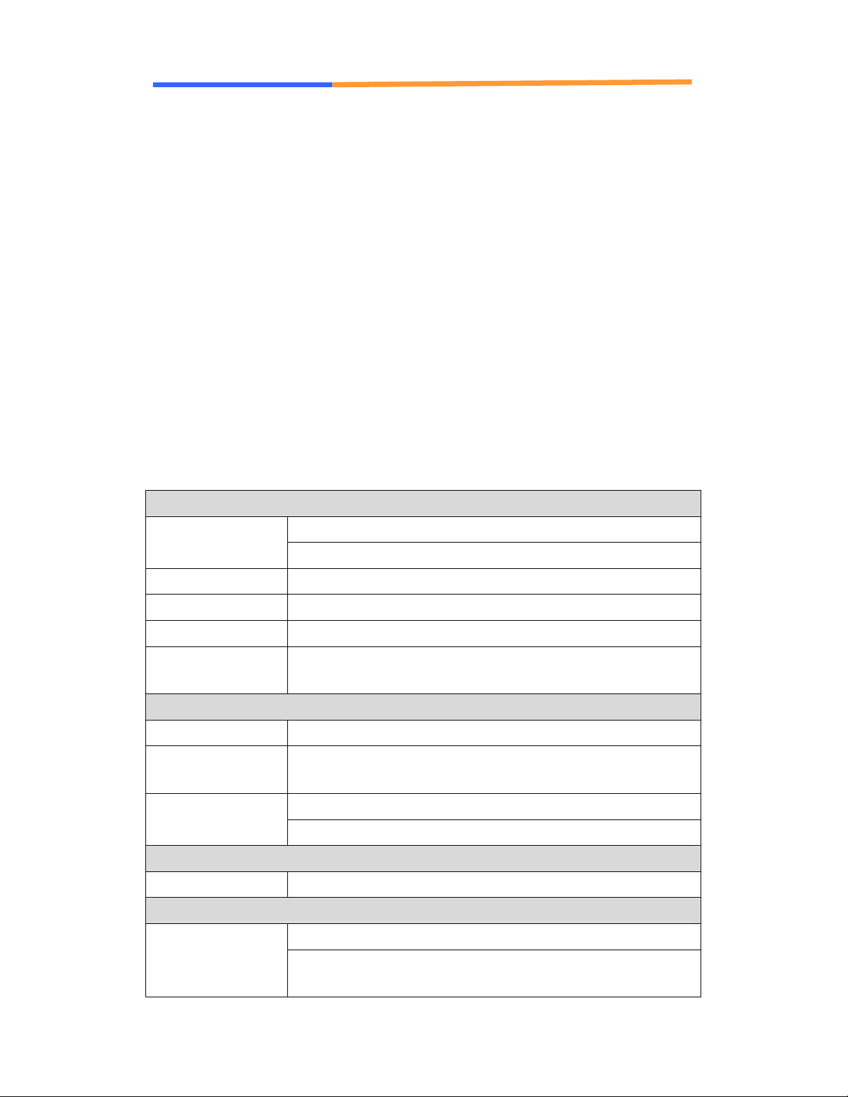
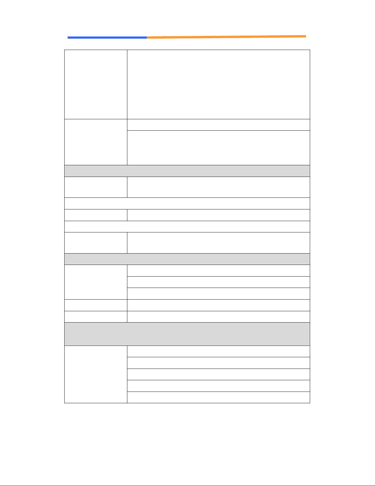
1.2 Specifications .............................................................................................. 4
1.3 Ordering Information................................................................................... 7
1.4 Packaging .................................................................................................... 7
1.5 Precautions .................................................................................................. 8
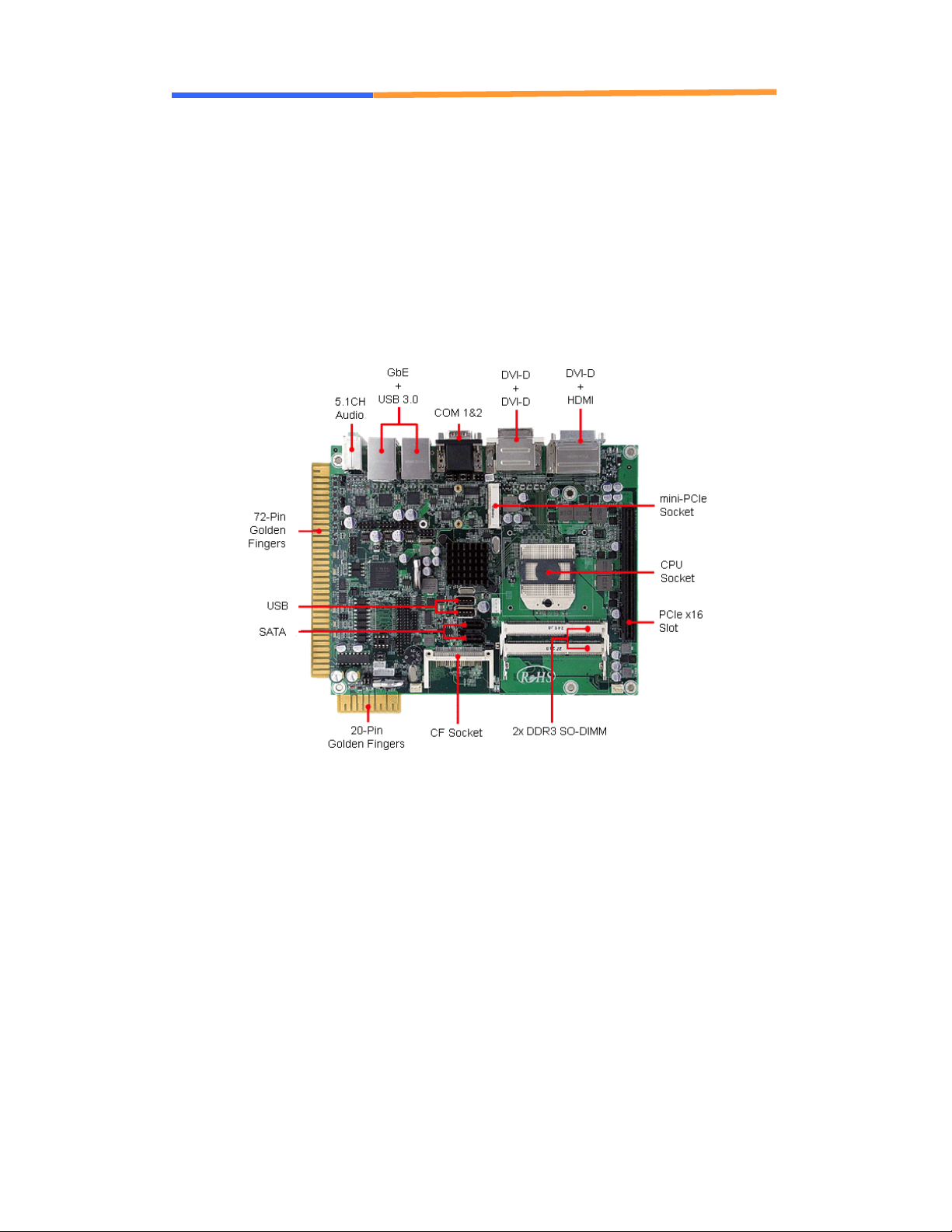
1.6 Board Placement.......................................................................................... 9
1.7 Board Dimensions ..................................................................................... 10
Chapter 2. Connector/Jumper Configuration.............................................................11
2.1 Connector/Jumper Location and Definition.................................................11
2.2 Connector and Jumper Setting.................................................................... 15
2.3 Compact Flash
™
Card Socket Pin Defininitions.......................................... 28
Chapter 3. BIOS Setup ............................................................................................ 29
3.1 Quick Setup ............................................................................................... 29
3.2 Entering the CMOS Setup Program............................................................ 30
3.3 Menu Options ............................................................................................ 32
3.4 Advanced Menu......................................................................................... 33
3.5 Chipset Menu............................................................................................. 43
3.6 Boot Menu................................................................................................. 51
3.7 Security Menu ........................................................................................... 54
3.8 Exit............................................................................................................ 55
Appendix A: Development Kit (optional) ................................................................ 56

User’s Manual
WIN Enterprises, Inc. MB-63010 User Manual
4
Chapter 1. General Information
1.1 Introduction
PL-63010 is the Box/System implementation of WIN's MB-63010 board that
features the AMD Fusion R-series APU, three DVI-D + one HDMI display, Dual
Giga Ethernet, four USB 3.0 + eight USB 2.0 interfaces, optional I/O and
security module for casino applications and more. The device provides
excellent performance for various applications such as multi-player,
multi-display, high-end 3D games. Windows
®
WES 7 and Linux Ubuntu 10/11
are supported. These devices also include an industry-standard 72-pin golden
finger connector for all gaming kits and the refurbishing machines market.
1.2 Specifications
■System
AMD
®
socket FS1r2 for R-series Quad/Dual coreCPU
APU, 35W max.
BIOS AMI
®
UEFI BIOS
Chipset AMI
®
A75
System Memory Two DDR3-1600 SODIMM socket support up to 16GB
Watchdog Timer 255 levels timer interval, (1sec. to 255min.), setup by
software
■Audio
Audio Chipset HDA
Power amp. 6W Stereo power amp.; jumpers for optional volume
control external VR
5+1 channel audio jack on rear edgeAudio Interface
2x amplified speaker out through golden finger
■Ethernet
Ethernet Interface 2x Gigabit Ethernet
■Storage
One CF socketSSD
Or 2GB PATA NANDrive (onboard optional); pin header
for write protection

User’s Manual
WIN Enterprises, Inc. MB-63010 User Manual
5
HDD Two SATA3.0 (6Gb/s) connectors with 4-pin SATA power
connector
■Security
CPU Security AES, RNG, Content protection
Physical Security Onboard Storage (optional)
DIP-8 socket for optional Crypto MemorySoftware Security
TPM 1.2 (optional)
■Gaming
NVRAM On-board battery backup of 32KB SRAM
Optional up to 4.5MB NVRAM or 2.5MB MRAM
Timers 1x 1mS timer and 4x Programmable timer with timeout
interrupt
EEPROM DIP 8-pin socket for optional I²C EEPROM or Crypto
Memory
Digital I/O 72-pin golden finger gaming I/O interface
- 15x Photo-isolated digital inputs
- 16x TTL digital inputs
- 24x 500mA current sink output by MOSFET
- 2x 2A high current sink output by MOSFET
FPGA All input with programmable de-bounce
Timer 4+1 with interrupt
32-bit Random Number Generator
Lamp outputs with programmable flash and dimming
Serious out for external lamps modules for decoration
Programmable PWM output
I/O expansion Pin header for optional gaming I/O & NVRAM expansion
module
■Expansion
One PCI-E x16 slot (PCIe x8 signal),
One mini-PCIe socket for PCIe x1 Or one mSATA (default
mSATA)
Expansion slot
LPC, I2C, SPI header
■System I/O

User’s Manual
WIN Enterprises, Inc. MB-63010 User Manual
6
COM 4x COM
- COM1 - Full RS-232, DB9
- COM2 - simple RS-232/RS-485, DB9
- COM3 - simple RS-232 (pin header)
or cctalk (jumper select)
- COM4 - simple RS-232 (pin header)
4x USB 3.0 port at rear I/OUSB
8x USB2.0 internal
- 2x by 180°Vertical type-A socket
- 6x by pin header
■Hardware monitoring
System Heath
Monitoring
Measurement of CPU core and system temperature with
thermal trip
■Power Supply
Voltage DC 5V & DC12V input from 20-pin Golden finger
■Software
O/S Microsoft® Windows® WES7 and Linux Ubuntu 10/11
support
■Mechanical and Environment
Operating Temperature: 0 – 60 ºC (32 ºF – 140 ºF)
Storage Temperature: -20 – 85 ºC (-4 ºF – 185 ºF)
Environmental
Relative Humidity: 10-85 % RH, non-condensing
Certifications FCC/CE Class A
Dimensions 170mm x 210mm
■Applications
Multi-display video slot/poker machine
Multi-display amusement machine
Multi-player Roulette/Baccarat system
Multi-player Racing/Shooting game
Main Applications
Bingo room island system

User’s Manual
WIN Enterprises, Inc. MB-63010 User Manual
7
1.3 Ordering Information
■Ordering Information
MB-63010 (board)
AMD R-series APU based Gaming Board with HDMI, 3x
DVI-D, 2x GbE, 4x COM, 4x USB 3.0
■Optional
- R217A-01; R217A I/O Testing Board
- CB-G00028-00; R217 I/O Testing Board Cable for
MB-63010
- CB-IUSB01-00; USB cable 2x5 (2.54mm)
- CB-S4B402-00; Dual end 4 Pin power cable.
DK-GA5010-01
- CB-SATA07-00; SATA Cable w/ 35cm
R283 Casino feature expansion module
Note: Specifications subject to change without prior notification.
1.4 Packaging
Please make sure that the following items have been included in the package
before installation.
1. MB-63010 board
2. Quick Installation Guide (Optional)
3. Cables (Optional)
4. CD-ROM that contains the following folders:
(1) Manual
(2) Driver
If any item of above is missing or damaged, please contact your dealer or
retailer from whom you purchased the MB-63010. Keep the box and carton for
shipping or storing MB-63010. After you unpack the goods make sure the
packaging is intact. Do not plug the power adapter of the appliance if you
already find it appears damaged.
Note: Keep the MB-63010 in its original packaging until you start installation.

User’s Manual
WIN Enterprises, Inc. MB-63010 User Manual
8
1.5 Precautions
Please make sure you properly ground yourself before handling the MB-63010
board or system components. Electrostatic discharge can be easily damage
the MB-63010 board.
Do not remove the anti-static packing until you are ready to install the
MB-63010 board.
Ground yourself before removing any system components from its protective
anti-static packaging. To ground yourself, grasp the expansion slot covers or
other unpainted parts of the computer chassis.
Handle the MB-63010 board by its edges and avoid touching the components
on it.

User’s Manual
WIN Enterprises, Inc. MB-63010 User Manual
9
1.6 Board Placement

User’s Manual
WIN Enterprises, Inc. MB-63010 User Manual
10
1.7 Board Dimensions

User’s Manual
WIN Enterprises, Inc. MB-63010 User Manual
11
Chapter 2. Connector/Jumper Configuration
2.1 Connector/Jumper Location and Definition
Connector:
CN1 HDMI Connector
CN2 COM 1/2 Connector (DB9*2)
CN3 DVI-D Port 2/3
CN4 Audio Jack
CN5 DVI-D Port 1
CN6 LAN1 & USB 0/1 (USB 3.0)
CN7 LAN2 & USB 2/3 (USB 3.0)
CN8 MINI-PCIE LED Connector (WLAN)

User’s Manual
WIN Enterprises, Inc. MB-63010 User Manual
12
CN9 MINI-PCIE Socket.
CN10 USB Port 2/3 (USB 2.0)
CN11 USB Port 4/5 (USB 2.0)
CN12 USB Port 6/7 (USB 2.0)
CN13 SPI Flahs Download Pin Header (For Debug
Purpose)
CN14 FPGA Download Pin Header (For Debug)
CN15 GOLDEN-FINGER1
CN16 PCIE x16 Socket (Supports x8 Only)
CN17 USB Port 1 (USB 2.0)
CN18 SATA Power Connector
CN19 USB Port 0 (USB 2.0)
CN20 Door Pin Header
CN21 R283 daughter board expansion
CN22 LPC Pin Header
CN23 SATA Port 0
CN24 R283 daughter board expansion
CN25 SATA Port 1
CN26 COM4 (Simple RS232)
CN27 CF Socket
CN28 COM3 (Simple RS232 / CCTALK)

User’s Manual
WIN Enterprises, Inc. MB-63010 User Manual
13
Jumpers:
JP1 COM2 MODE SELECT
(1-3short 2-4short : RS232 ; 3-5short 4-6short : RS485)
JP2 COM2 MODE SELECT
(1-3short 2-4short : RS232 ; 3-5short 4-6short : RS485)
JP3 COM2 MODE SELECT
(1-2: RS232 ; 3-4: RS485 4-Wire ; 5-6: RS485 2-Wire)
JP4 GPO Port Power Level Select
(1-2: +5V ; 2-3: +12V)
JP5 GPO Port Power Level Select
(1-2: +5V ; 2-3: +12V)
JP6 GPO Port Power Level Select
(1-2: +5V ; 2-3: +12V)
JP7 FPGA RESERVED
JP8 GPI Port Power Level Select
(1-2: +5V ; 2-3: +12V)

User’s Manual
WIN Enterprises, Inc. MB-63010 User Manual
14
JP9 GPI Port Power Level Select
(1-2: +5V ; 2-3: +12V)
JP10 RESET
JP11 EEPROM_WP (1-2:ON 2-3OFF)
JP12 NANDrive_WP_N(1-2:ON 2-3:OFF)
JP13 COM3 MODE SELECT
(1-3short 2-4short: SIM232; 3-5short 4-6short: CCTALK)
JP14 AUDIO
(1-3short 2-4short: Audio ON; 3-5short 4-6short: Audio OFF)
JP15 Clear CMOS
(1-2: Hold CMOS; 2-3: Clear CMOS)

User’s Manual
WIN Enterprises, Inc. MB-63010 User Manual
15
2.2 Connector and Jumper Settings
CN1: HDMI
Pin
Signal Pin Signal
1 TMDS Data2+ 11 TMDS Clock Shield
2 TMDS Data2 Shield 12 TMDS Clock-
3 TMDS Data2- 13 CEC (Control)
4 TMDS Data1+ 14 Reserved (N.C.)
5 TMDS Data1 Shield 15 SCL (DDC clock)
6 TMDS Data1- 16 SDA (DDC data)
7 TMDS Data0+ 17 DDC/CEC Ground
8 TMDS Data0 Shield 18 +5V Power (power EDID/DDC)
9 TMDS Data0- 19 Hot Plug detect
10 TMDS Clock+
CN2: COM1 & COM2
Pin Signal Pin Signal
A1 DCD B1 DCD
A2 RXD B2 RXD
A3 TXD B3 TXD
A4 DTR B4 DTR
A5 Ground B5 Ground
A6 DSR B6 DSR
A7 RTS B7 RTS
A8 CTS B8 CTS
A9 R1 B9 R1

User’s Manual
WIN Enterprises, Inc. MB-63010 User Manual
16
CN3: DVI-D Port 2/3
Pin Define Pin Define
M1
CASE GND
M2
CASE GND
CK1
DP0_TX0_N
CK2
DP0_TX0_P
CK3
GND
CK4
-
CK5
-
CK6
DP0_AUX_P
CK7
DP0_AUX_N
CK8
-
CK9
DP0_TX1_N
CK10
DP0_TX1_P
CK11
GND
CK12
-
CK13
-
CK14
+5V
CK15
GND
CK16
DVID_HPD
CK17
DP0_TX2_N
CK18
DP0_TX2_P
CK19
GND
CK20
-
CK21
-
CK22
GND
CK23
DP0_TX3_N
CK24
DP0_TX3_P
C1
C2
C3
-
C4
-
C5
-
CN4A: AUDIO Connector
Pin
Define Pin
Define
2 MIC_L 3 GND
4 MIC_JD
5 MIC_R

User’s Manual
WIN Enterprises, Inc. MB-63010 User Manual
17
CN4B: AUDIO Connector
Pin
Define Pin
Define
22 SPKR_OUT_L
23 GND
24 FRONT_JD 25 SPKR_OU T_R
CN4C: AUDIO Connector
Pin
Define Pin
Define
32 LINE_L
33 GND
34 LINE_JD
35 LINE_R
CN5: DVI-D Port 1
Pin Define Pin Define
M1
CASE GND
M2
CASE GND
CK1
DP0_TX0_N
CK2
DP0_TX0_P
CK3
GND
CK4
-
CK5
-
CK6
DP0_AUX_P
CK7
DP0_AUX_N
CK8
-
CK9
DP0_TX1_N
CK10
DP0_TX1_P

User’s Manual
WIN Enterprises, Inc. MB-63010 User Manual
18
CK11
GND
CK12
-
CK13
-
CK14
+5V
CK15
GND
CK16
DVID_HPD
CK17
DP0_TX2_N
CK18
DP0_TX2_P
CK19
GND
CK20
-
CK21
-
CK22
GND
CK23
DP0_TX3_N
CK24
DP0_TX3_P
C1
C2
C3
-
C4
-
C5
-
CN6/7: USB and 1000/100 LAN RJ45 Jack
Pin Signal Pin Signal
1 5VUSB0 1
TX+
2 USBDT0- 2 TX-
3 USBDT0+ 3 N/C
4 Ground 4 Ground
5 5VUSB0 5 Ground
6 USBDT1- 6 N/C
7 USBDT1+ 7 RX+
8 Ground 8 RX-
CN8: MINI-PCIE LED Connector (WLAN)
Pin
Define Pin
Define
1 MINIPCIE_LED1
2 MINIPCIE_WLAN_N

User’s Manual
WIN Enterprises, Inc. MB-63010 User Manual
19
CN9: mSATA (Default) / mini-PCIE Socket.
Pin Define Pin Define
1
WAKE#
27
GND
2
3.3V
28
+1.5V
3
RESERVED
29
GND
4
GND
30
SMB_CLK
5
RESERVED
31
PETN0
6
1.5V
32
SMB_DATA
7
CLKREQ#
33
PETP0
8
RESERVED
34
GND
9
GND
35
GND
10
RESERVED
36
USB_D-
11
REFCLK-
37
RESERVED
12
RESERVED
38
USB_D+
13
REFCLK+
39
RESERVED
14
RESERVED
40
GND
15
GND
41
-
RESERVED
16
RESERVED
42
LED_WWAN#
17
RESERVED
43
RESERVED
18
GND
44
LED_WLAN#
19
RESERVED
45
RESERVED
20
RESERVED
46
LED_WPAN#
21
GND
47
RESERVED
22
PERST#
48
+1.5V
23
PERN0
49
RESERVED
24
+3.3VAUX
50
GND
25
PERP0
51
RESERVED
26
GND
52
+3.3V

User’s Manual
WIN Enterprises, Inc. MB-63010 User Manual
20
CN10/11/12:
USB pin header
Pin
Define Pin
Define
1 +5V 2 +5V
3 USBDATA-
4 USBDATA-
5 USBDATA+
6 USBDATA+
7 GND 8 GND
9 Reserved
10 GND
CN13:
SPI Flash Download Pin Header (For Debug Purposes)
Pin
Define Pin
Define
1 +V3P3_SPI 2 GND
3 FCH_SPI_CS_N
4 FCH_SPI_CLK
5 FCH_SPI_DATAIN
6 FCH_SPI_DATAOUT
7 N.C. 8 N.C.
This manual suits for next models
1
Table of contents
Other WIN Enterprises Motherboard manuals