WIN Enterprises PL-80500 User manual

User’s Manual
WIN Enterprises, Inc. Sep., 2014
1
PL-80500
Networking Appliance
1U Rack-Mount Intel® Atom Processor C2000 Network System,
8 Copper GbE, SATA, CF, LCM, PCI-E
User’s Manual
Version 1.1

User’s Manual
WIN Enterprises, Inc. Sep., 2014
2
Reversion History
Date
Version
Modification
Editor
2014/9/8 1.0 First Release T. Sirois
2014/9/20 1.1 Jumper setting section update T. Sirois

User’s Manual
WIN Enterprises, Inc. Sep., 2014
3
© Copyright 2004. All Rights Reserved
This document contains proprietary information protected by copyright. All rights are reserved; no
part of this manual may be reproduced, copied, translated or transmitted in any form or by any means
without prior written permission of the manufacturer.
The content of this document is intended to be accurate and reliable; the original manufacturer assumes
no responsibility for any inaccuracies that may be contained in this manual. The original manufacturer
reserves the right to make improvements to the products described in this manual at any time without
prior notice.
Trademarks
IBM, EGA, VGA, XT/AT, OS/2 and PS/2 are registered trademarks of International business Machine
Corporation
Award is a trademark of Award Software International, Inc
Intel is a trademark of Intel
RTL is a trademark of Realtek
VIA is a trademark of VIA Technologies, Inc
Microsoft, Windows, Windows NT and MS-DOS are either trademarks or registered trademarks of
Microsoft Corporation
All other product names mentioned herein are used for identification purpose only and may be
trademarks and/or registered trademarks of their respective companies
Limitation of Liability
While reasonable efforts have been made to ensure the accuracy of this document, the manufacturer
and distributor assume no liability resulting from errors or omissions in this document, or from the use
of the information contained herein.
For more information on PL-80500 or other WIN Enterprises products, please visit our website:
www.win-ent.com.
For technical supports or free catalog, please send your inquiry to:
sales@win-ent.com.

User’s Manual
WIN Enterprises, Inc. Sep., 2014
4
Table of Contents
Chapter 1. General Information....................................................................... 5
1.1 Introduction ................................................................................................... 5
1.2 Specifications ................................................................................................ 5
1.3 Order Information.......................................................................................... 7
1.4 Packaging ...................................................................................................... 8
1.5 Precautions .................................................................................................... 8
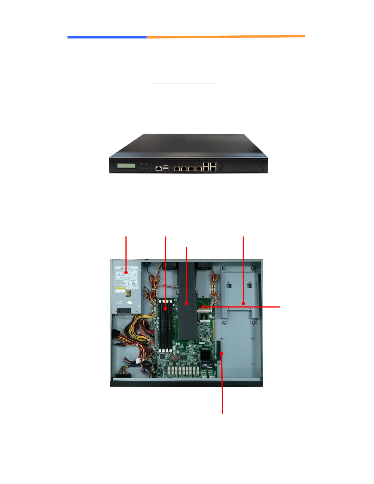
1.6 System Layout............................................................................................... 9
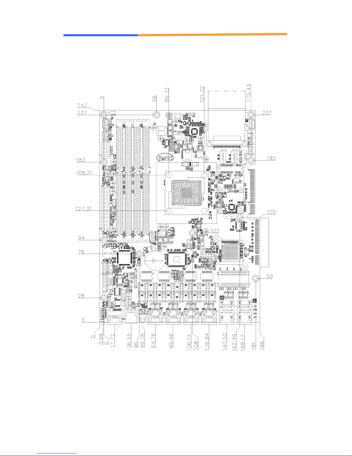
1.7 Board Dimensions ....................................................................................... 10
Chapter 2. Connector/Jumper Configuration ................................................11
2.1 Connector/Jumper Location and Definition...................................................11
2.2 Connector and Jumper Setting ..................................................................... 13
2.3 CompactFlashTM Card Socket Pin Define................................................... 23
Chapter 3. Optional GbE Module & Riser Card Setting.............................. 24
3.1 R119: Ethernet module with two GbE Copper and two GbE SFP................. 24
3.2 R120: Ethernet module with four GbE SFP.................................................. 25
3.3 R121: Ethernet module with two GbE Copper or SFP.................................. 26
3.4 R122: Ethernet module with four GbE Copper............................................. 27
3.5 R127: Ethernet module with eight GbE Copper............................................ 28
3.7 R137: Ethernet module with four GbE Copper............................................. 30
3.8 R117: Riser card for expansion module PCIE x8....................................... 31
3.9 R118: Riser card for PCIE x8 add-on card................................................. 31
3.10 R168: Ethernet module with four GbE Copper and bypass......................... 32
3.11 R169: Ethernet module with four GbE SFP................................................ 33
3.12 R171: Ethernet module with eight GbE Copper.......................................... 34
3.13 R175: Ethernet module with four GbE Copper and bypass......................... 35
Chapter 4. Utility & Driver Installation ........................................................... 38
4.1 Operation System Supporting ...................................................................... 38
4.2 System Driver Installation............................................................................ 39
4.3 LAN Driver Installation ............................................................................... 39
Appendix A: Watchdog Timer Programming Guide ........................................... 40
Appendix B: LAN Bypass Programming Guide................................................. 41
Appendix C: Cable Development Kit................................................................. 42

User’s Manual
WIN Enterprises, Inc. Sep., 2014
5
Chapter 1. General Information
1.1 Introduction
The PL-80500 is a 1U rack-mounted hardware platform designed for high
performance network service applications. Supporting the next generation
Intel® Atom™ Processor C2000 product family (formerly codenamed
Rangeley) with 8/4/2 Cores; the new platform comes fully packed with Intel®
AES New Instructions (Intel® AES-NI), Intel® Quick Assist Technology and
Intel® Streaming SIMD Extension (Intel®SSE) for hardware accelerated data
encryption and decryption.
The platform supports four DDR3 1333/1600MHz unbuffered ECC or non-ECC
DIMM sockets up to 32GB of memory and offers powerful storage interface
supporting 2.5”/3.5" SATA 3.0 6Gbps hard drives and CompactFlash™, thus
granting the best network performance and maximum utilization. In order to
enhance network security performance, the PL-80500 offers optional Intel
Quick Assist technology that provides hardware-level cryptographic
acceleration, hence enabling the reallocation of CPU computing power for
higher-layer packet processing.
This platform offers 8 GbE to 16 GbE Ethernet ports via PCIe on the front
panel. To prevent network problems during unexpected shut downs, PL-80500
supports two segments of LAN bypass function through WDT and GPIO pin
definitions. For local system management, maintenance and diagnostics; the
front panel is equipped with dual USB 2.0 ports, one RJ-45 console port and
LED indicators that monitor power and storage device activities. Additionally,
the PL-80500 supports one PCIe x8 slot for add-on Ethernet module and one
PCIe x4 golden finger for standard PCIe card via a riser card.
1.2 Specifications
CPU Support Intel® Atom C2000 family
processor, FCBGA (codenamed
Rangeley)
Chipset IntelC2000 family processor
Processor System
BIOS AMIUEFI BIOS
Memory Technology Dual-channel, ECC/Non-ECC,
un-buffered, DDR3/L 1333/1600MHz

User’s Manual
WIN Enterprises, Inc. Sep., 2014
6
memory
Capacity Up to 32GB with 4 DIMM sockets
Expansion Expansion Slots - one PCIE x8 slot for add-on Ethernet
module
- one PCIE x4 golden finger for
standard PCIE slot (optional Riser
card)
GbE Ethernet Eight Copper GbE ports, Marvell
88E1543 via SGMII, Intel 82580 via
PCIe x4
2~8 GbE ports (optional add-on
Ethernet module)
Ethernet
LAN Bypass two pairs bypass
H/W Acceleration Security Processor Optional module with Cavium NITROX
PX CN16xx.
SATA Internal HDD bay support one 3.5” or
two 2.5” SATA HDD
Storage
Compact Flash Socket One CompactFlash
TM
Type II
USB One external USB 2.0 Dual port
One internal USB 2.0 (5x2 pin header)
I/O
Serial One RJ45 Console port (COM1)
One internal 5x2 pin header (COM2)
Power Supply Watt 1U ATX single power supply
Form Factor 1U rack-mount
LCD Module one 16x2 LCM
Keypad Four buttons keypad
LED One Power LED (Green)
One Status LED (Green/ Yellow)
One HDD LED (Yellow)
Two Bypass LED (Red)
Dimension
(
W x D x H
)
430mm (W) x 350mm (D) x 44mm (H)
(16.9”W x 13.8”D x 1.7”H)
Operating Temperature Operating: 0 ~ 40°C ( 32 ~ 104°F )
Storage Temperature -20 ~ 75°C (-4 ~ 167°F)
Mechanical and
Environment
Humidity 10 ~ 85% relative humidity,
non-operating, non-condensing
Weight 1pc/CTN, 10kgs, 55.5cm(W) x 54cm(D) x 22.5cm(H)

User’s Manual
WIN Enterprises, Inc. Sep., 2014
7
Certification CE/FCC
1.3 Order Information
We offer some accessories for PL-80500 appliance for customer need.
PL-80500A-O24 1U Rack-Mount Intel® Atom C2758 2.4GHz 8 Cores Processor Network
System, 8 Copper GbE, SATA, CF, LCM, PCI-E, Quick Assist
PL-80500B-Q24 1U Rack-Mount Intel® Atom C2538 2.4GHz 4 Cores Processor Network
System, 8 Copper GbE, SATA, CF, LCM, PCI-E
Optional
R168 Expansion module with 4 Copper GbE, Intel 82580EB, PCIE 2.0
Two pair bypass function (option)
R169A Expansion module with 4 SFP GbE, Intel 82580EB, PCIE 2.0
R171A Expansion module with 8 Copper GbE, Intel 82580EB, PCIE 2.0
R175 Expansion module with 4 Copper GbE, Intel 82574L/82583V, PCIE x1,
2 pair bypass
R175C Expansion module with 4 Copper GbE, Intel 82574L/82583V, PCIE x1
R186A Expansion module with 4 SFP ports & 4 Copper GbE ports, Intel
82580EB
R186B Expansion module with 4 SFP ports & 4 Copper GbE ports with two pair
bypass, Intel 82580EB
R188A Expansion module with Two 10GbE SFP+ ports, Intel 82599ES
R199A IPMI Module, PCIE x 1, Aspeed AST2150 Chip
R297 Expansion module with 4 Copper GbE ports, Intel I211AT
Two pair bypass function (option)
R298 Expansion module with Cavium 1610 and 4 Copper GbE
DK002 Cable development kit:
CB-CO5204-00 Cross over 2M
CB-DB9200-01 Null modem cable 2M
CB-EC5200-00 Ethernet cat.5 cable 2M
CB-IPS200-00 KBMS cable, 15CM
CB-IUSB2B-00 USB cable, 25CM
CB-IVGA01-00 VGA cable, 20CM
CB-RJDB91-00 RJ-45 to DB-9 cable 2M

User’s Manual
WIN Enterprises, Inc. Sep., 2014
8
1.4 Packaging
Please make sure that the following items have been included in the package
before installation.
1. PL-80500 Appliance
2. Quick Installation Guide (Optional)
3. Cables (Optional)
4. CD-ROM that contains the following folders:
(1) Manual
(2) System Driver
(3) Ethernet Driver
(4) Utility Tools
If any of the above items are missing or damaged, please contact your dealer
or retailer from whom you purchased the PL-80500. Keep the box and carton
when you ship the PL-80500. After you unpack the goods, inspect and make
sure the packaging is intact. Do not plug the power adapter to the appliance of
PL-80500 if you find it's damaged.
Note: Keep the PL-80500 in the original packaging until you start installation.
1.5 Precautions
Please make sure you properly ground yourself before handling the PL-80500
appliance or other system components. Electrostatic discharge can be easily
damage the PL-80500 appliance.
Do not remove the anti-static packing until you are ready to install the
PL-80500 appliance.
Ground yourself before removing any system component from it protective
anti-static packaging. To ground yourself, grasp the expansion slot covers or
other unpainted parts of the computer chassis.
Handle the PL-80500 appliance by its edges and avoid touching its
components.

User’s Manual
WIN Enterprises, Inc. Sep., 2014
9
1.6 System Layout
PL-80500 Front Side
CF
PCIe slot for
Ethernet module
CPU
DDR3 Socket
Power supply HDD bay (optional)

User’s Manual
WIN Enterprises, Inc. Sep., 2014
10
1.7 Board Dimensions:

User’s Manual
WIN Enterprises, Inc. Sep., 2014
11
Chapter 2. Connector/Jumper Configuration
2.1 Connector/Jumper Location and Definition
Connector Define Connector Define
CN1 ATX Power Switch Pin Header CN21 LAN7/LAN8 connector
CN2 80 port connector CN22 Reset connector
CN3 ATX +12V power connector
(8-Pin)
CN23 USB connector (Dual)
CN4 SPI connector CN24 LAN1 connector
CN5 SATA connector CN25 LAN2 connector
CN6 SATA connector CN26 LAN3 connector
CN7 SATA power connector CN27 LAN4 connector
CN8 Mini PCIE connector CN28 COM1 connector (RJ45)
CN9 ATX power connector (24-Pin) LED1 Rear Side LEDs
CN10 PEX8 SLOT SW1 Button for GPI or Reset
CN11 Case open connector JP1 DDR Voltage Selection
(1.5V/1.35V)
CN12 Debug GPIO connector JP2 5V power for FG1
CN13 PGO connector JP3 5V power for CN10
CN14 PS2 KB/MS connector JP4 LAN1 & LAN2 Bypass Selection
CN15 COM2 connector (Header) JP5 Clear CMOS
CN16 PGI connector JP6 LAN3 & LAN4 Bypass Selection
CN17 LCM connector JP7 AT/ATX Selection
CN18 USB connector (2.54mm
Header) JP8
Watchdog Function Selection
CN19 Keypad connector JP9 SW1 Function Selection
CN20 LAN5/LAN6 connector

User’s Manual
WIN Enterprises, Inc. Sep., 2014
12

User’s Manual
WIN Enterprises, Inc. Sep., 2014
13
2.2 Connector and Jumper Setting
CN1
:
::
:
ATX Power Switch Pin Header
Pin
Define
1
5VSB
2
SIGNAL
CN3
:
::
:
ATX +12V Power Connector (8Pin)
Pin Define Pin Define
1 Ground 5 +12V
2 Ground 6 +12V
3 Ground 7 +12V
4 Ground 8 +12V
CN5,6,7
:
::
:
SATA Connector
Pin
Signal
1
Ground
2
TXP
3
TXN
4
Ground
5
RXN
6
RXP
7
Ground
FAN 1 /2 /3 /4 /5 /6 : FAN Connector

User’s Manual
WIN Enterprises, Inc. Sep., 2014
14
Pin
Define
1
GND
2
+12V
3
Speed Detect
4
Control
CN8: MINI-PCIE Connector
MINI_PCIE
WAKE#
13.3V 2
RESERVED
3
RESERVED
5
CLKREQ#
7
GND
9
REFCLK-
11
REFCLK+
13
GND
15
RESERVED
17
RESERVED
19
GND
21
PERN0
23
PERP0
25
GND
27
GND
29
PETN0
31
PETP0
33
GND
35
RESERVED
37
RESERVED
39
RESERVED
41
RESERVED
43
RESERVED
45
RESERVED
47
RESERVED
49
RESERVED
51 +3.3V 52
GND 50
+1.5V 48
LED_WPAN# 46
LED_WLAN# 44
LED_WWAN# 42
GND 40
USB_D+ 38
USB_D- 36
GND 34
SMB_DATA 32
SMB_CLK 30
+1.5V 28
GND 26
+3.3VAUX 24
PERST# 22
RESERVED 20
GND 18
RESERVED 16
RESERVED 14
RESERVED 12
RESERVED 10
RESERVED 8
1.5V 6
GND 4
Pin
Define Pin
Define
1 WAKE# 2 3.3V
3 Reserved
4 GND
5 Reserved
6
1.5V
7
CLKREQ#
8
Reserved
9
GND
10
Reserved
11
REFCLK-
12
Reserved
13
REFCLK+
14
Reserved
15
GND
16
Reserved
17
Reserved
18
GND
19
Reserved
20
Reserved
CN9
:
::
:
ATX Power Connector

User’s Manual
WIN Enterprises, Inc. Sep., 2014
15
Pin Define Pin
Define
11 +3.3V 1 +3.3V
12 -12V 2 +3.3V
13 GND 3 GND
14 PS_ON* 4 +5V
15 GND 5 GND
16 GND 6 +5V
17 GND 7 GND
18 RSVD 8 POWER GOOD
19 +5V 9 5VSB
20 +5V 10 +12V
CN10
:
::
:
PCIE x8 Slot
Pin Define Pin Define
A1 GND B1 +12V
A2 +12V B2 +12V
A3 +12V B3 +12V
A4 GND B4 GND
A5 +3.3V B5 SMB_CLK_R
ESUME
A6 +3.3V B6 SMB_DATA_
RESUME
A7 GND B7 GND
A8 +3.3V B8 +3.3V
A9 +3.3V B9 NC
A10
+3.3V B10
+3.3V_STBY
A11
RESET B11
PE_WAKE
A12
GND B12
PWROK
A13
CLK_100MP B13
GND
A14
CLK_100MN
B14
TX_0_DP
A15
GND B15
TX_0_DN
A16
RX_0_DP B16
GND
A17
RX_0_DN B17
VCC5_SLOT

User’s Manual
WIN Enterprises, Inc. Sep., 2014
16
A18
GND B18
GND
A19
VCC5 B19
TX_1_DP
A20
GND B20
TX_1_DN
A21
RX_1_DP B21
GND
A22
RX_1_DN B22
GND
A23
GND B23
TX_2_DP
A24
GND B24
TX_2_DN
A25
RX_2_DP B25
GND
A26
RX_2_DN B26
GND
A27
GND B27
TX_3_DP
A28
GND B28
TX_3_DN
A29
RX_3_DP B29
GND
A30
RX_3_DN B30
WatchDog
-Bypass
A31
GND B31
GPIO53
A32
GPIO55 B32
GND
A33
PCI-E_CFG2 B33
TX_4_DP
A34
GND B34
TX_4_DN
A35
RX_4_DP B35
GND
A36
RX_4_DN B36
GND
A37
GND B37
TX_5_DP
A38
GND B38
TX_5_DN
A39
RX_5_DP B39
GND
A40
RX_5_DN B40
GND
A41
GND B41
TX_6_DP
A42
GND B42
TX_6_DN
A43
RX_6_DP B43
GND
A44
RX_6_DN B44
GND
A45
GND B45
TX_7_DP
A46
GND B46
TX_7_DN
A47
RX_7_DP B47
GND
A48
RX_7_DN B48
PCI-E_CFG1
A49
GND B49
GND
CN14
:
::
:
PS2 KB/MS Pin Header

User’s Manual
WIN Enterprises, Inc. Sep., 2014
17
Pin Define Pin Define
1 KCLK 2 MCLK
3 KDAT 4 MDAT
5 N/A 6 N/A
7 PS2_GND
8 PS2_GND
9 PS2_VCC
10 PS2_VCC
CN15
:
::
:
COM2 Box Header
Pin Define
Pin
Define
1 DCD# 6 DSR#
2 RXD# 7 RTS#
3 TXD# 8 CTS#
4 DTR# 9 RI#2
5 Ground 10 N/A
CN17
:
::
:
LCM Pin Header
Pin Define Pin Define
1 +5V 2 Ground
3 AFD# 4 N/A
5 INIT# 6 SLIN#
7 PD1 8 PD0
9 PD3 10 PD2
11 PD5 12 PD4
13 PD7 14 PD6
15 BLN 16 BLP

User’s Manual
WIN Enterprises, Inc. Sep., 2014
18
CN18
:
::
:
USB Pin Header
Pin
Define Pin
Define
1 +5V 2 +5V
3 USB1N 4 USB2N-
5 USB1P 6 USB2P
7 Ground 8 Ground
9 N/A 10
Ground
CN19
:
::
:
KEYPAD Pin Header
Pin Define
1 ACK#
2 BUSY
3 PE
4 SLCT
5 Ground
CN20/CN21/CN 24/CN25/CN26/CN27
:
::
:
Giga LAN RJ45 Connector
Pin Define
1 MDI0+
2 MDI0-
3 MDI1+
4 MDI2+
5 MDI2-
6 MDI1-

User’s Manual
WIN Enterprises, Inc. Sep., 2014
19
7 MDI3+
8 MDI3-
LED:
D2 : Link/Activity LED
Link Green
Activity Blinking
D1 : Bi-Color Speed LED
10 Mbps Off
100 Mbps Yellow
1000Mbps Green
CN22
:
::
:
Reset Pin Header
Pin Define
1 Ground
2 Reset #
CN23
:
::
:
USB0/1 Connector
Pin Define
1 +5V_USB
2 USBDT0-
3 USBDT0+
4 Ground
5 +5V_USB
6 USBDT1-
7 USBDT1+
8 Ground

User’s Manual
WIN Enterprises, Inc. Sep., 2014
20
JP1: DDR Voltage selection (1.5V/1.35V)
Pin Setting
1-2
DDR Voltage
1.5V (Default)
2-3
DDR Voltage
1.35V
JP2: 5V power for FG1
On 5V
Off Normal(default)
JP3: 5V power for CN10
On 5V
Off Normal(default)
JP4 : LAN1-2 Bypass Selection
Pin Setting
1-2
Bypass Always
Enabled
2-3
Disabled
(Default)
JP5: Clear CMOS
Pin Setting
1-2
Normal(Default)
Table of contents
Popular Server manuals by other brands

IBM
IBM eserver pSeries 690 installation guide

DCB
DCB EtherPath SS-1R quick start guide

Dell
Dell PowerEdge 2800 Conversion guideline

Compaq
Compaq ML370 - ProLiant - G3 Maintenance and service guide

Fujitsu
Fujitsu PRIMEQUEST 2000 Series installation manual

GRASS VALLEY
GRASS VALLEY K2 BASECAMP EXPRESS datasheet