WINIA KOS-61HB User manual

Microwave Oven
KOS-61HB
SERVICE MANUAL

第1 页共11 页
Donlim weili electrical appliances co., Ltd.
ADDRESS: ZHENGHE SOUTH ROAD, LELIU TOWN, SHUNDE DISTRICT, FOSHAN CITY,
GUANGDONG PROVINCE, CHINA
CONTENTS
1.PRECAUTION
2.SPECIFICATION
3.DISASSEMBLYAND REASSEMBLY
4.ALIGNMENTAND ADJUSTMENT
5.OUTPUT OF MAGNETRON
6.CHECK FOR MICROWAVE LEAKAGE
7.SCHEMATIC DIAGRAM
PRECAUTIONS TO BE OBSERVED BEFORE AND DURING
SERVING TO AVOID POSSIBLE EXPOSURE TO EXCESSIVE
MICROWAVE ENERGY
A) Do not operate or allow the oven to be operated with the door open.
B) Make the following safety checks on all ovens to be serviced before activating. The
magnetron or other microwave source, and make repairs as necessary:
1. Interlock operation.
2. Proper door closing.
3. Seal and sealing surfaces (arcing, wear, and other damage).
4. Damage to or loosening of hinges and latches.
5. Evidence of dropping or abuse.
C) Before turning on microwave power for any service test or inspection within the
microwave generating compartments, check the magnetron, wave guide or transmission line,
and cavity for proper alignment, integrity and connection.
D) Any defective or misadjusted components in the interlock, monitor, door seal, and
microwave generation and transmission systems shall be repaired, replaced, or adjusted by

第2 页共11 页
procedures described in this manual before the oven is release to the owner.
E) A microwave leakage check to verify compliance with the Federal performance standard
should be performed on each oven prior to release to the owner.
SAFETY PRECAUTION
Follow the special safety precautions, although microwave oven is completely safe when in
use. Repair work will be extremely hazardous to possible exposure to microwave radiation, as
well as potentially the high voltage and currents.
1. All serving should be done in comply with procedure described in this manual.
2. Microwave emission checks should be performed prior to serving if the oven is operative.
3. If the oven operates with door open, tell the user not to operate the oven and contact the
manufacturer and the centre for device and radiological health immediately.
4. Inform the manufacturer or importer when the oven emits micro leakage more than 5mA /cm2.
And tell the user the oven should not be used until it has been repaired.
5. Check the groundings.
6. Do not remove microwave oven from a prong AC cord. Be sure that all of the built-in
protect devices are replaced. Restore any missing protect facility.
7. When reinstalling the chassis and its assembly make sure that all protective facilities are in
place, including: nonmetallic control knobs and compartment covers.
8. Make sure that there are no cabinet opening through which people -particularly -children
-might insert object and contact dangerous voltage.
9. Service technician should remove their watches while repairing an microwave oven.
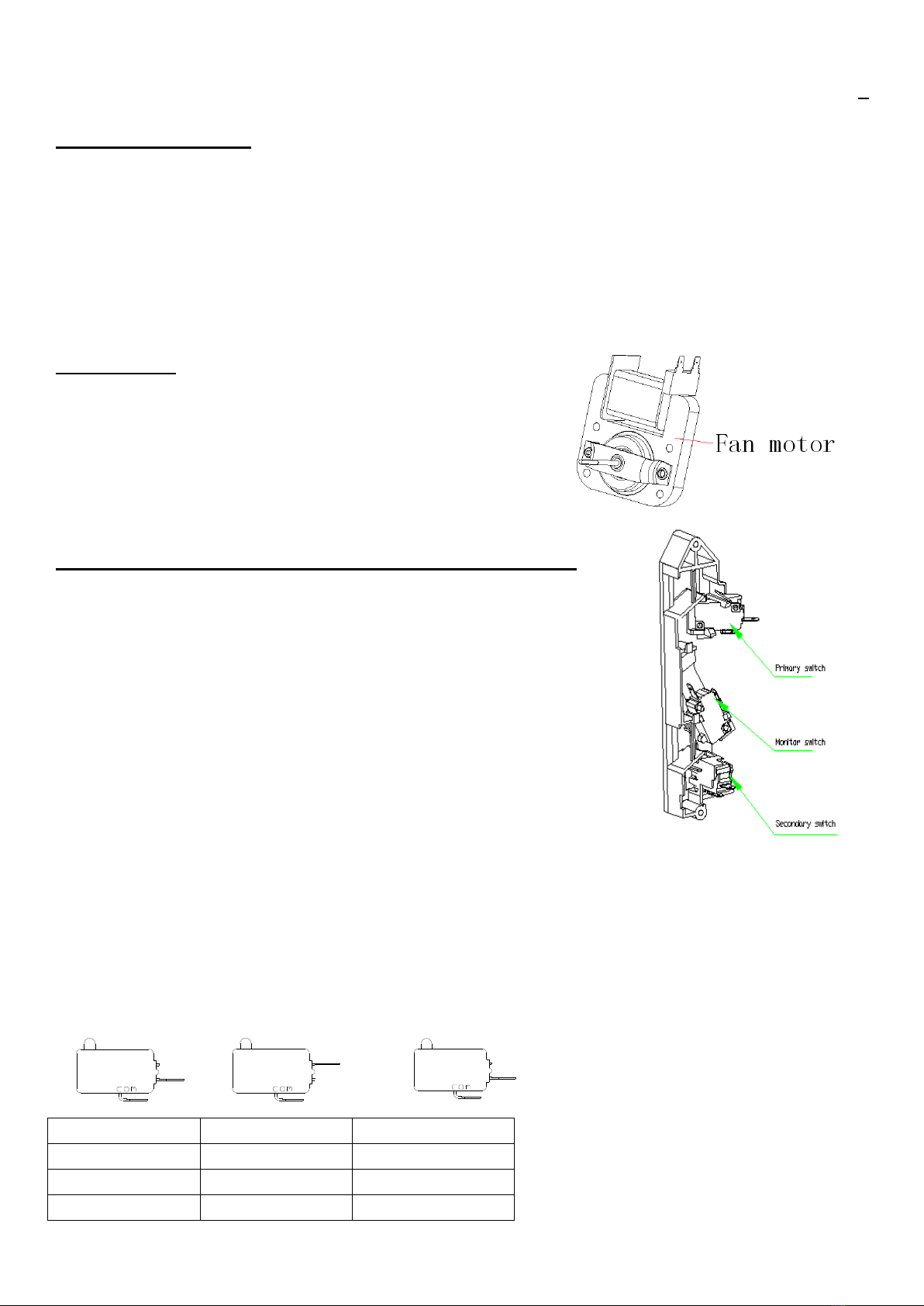
10. To avoid any possible radiation hazard, replace parts in accordance with the wiring
diagram. Also use only the exact replacement for the following parts: Primary and secondary
interlock switches, interlock monitor switch.
11. If the fuse is blown by the interlock switch, replace all of the following at the same time:
Primary, door switch and power relay. As well as the interlock switch as described in other
section of the manual.
12. Design alteration warning: When replace the critical component, select the component that
specified in list in the section of manual. Never attempt to change mechanical or electrical
design of MWO. Always disconnect the power source before disassembling or putting on
component.
13. Some semiconductor devices are easily damaged by static electricity. So touching a known
earth ground before you handling any semiconductor components or assemblies.
14. Always connect a test instrument ground lead to the instrument chassis ground before
connecting the positive lead; always remove the instrument ground lead at last.
15. When checking the continuity of the switches or transformer, always make sure that the
power is OFF. And one of the lead wires is disconnected.

第3 页共11 页
16. Use replacement component that has the same specification especially for flame resistance
and dielectric strength rating. The replacement component which does not have same safe
character may have a risk of fire or electrical shock.
17.) Save this manual.
HIGH VOLTAGE PRECAUTION
High voltage Warning:
Do not attempt to measure any of high voltage as high voltage is present during any cook
cycles.
Before touching any component or wring always unplug the oven and discharge the voltage
capacitor.
The high voltage capacitor remains charge about 30 seconds after disconnection, short the
negative terminal of H. V capacitor to the oven chassis (use a screwdriver).
High voltage is maintained with specified limits tolerance by safe -related parts and
calibration. If the high voltage exceeds the specified limits, check the relative component.
Precaution
HIGH VOLTAGE ELECTRICITY with high current
capability
presents in the circuit of High VOLTAGE
TRANSFORMER secondary and filament terminals,
it is extremely dangerous to work
on
or near these circuit with oven energized. Do
not measure the voltage in high voltage circuit
including voltage of magnetron.
Short the high voltage capacitor by using a
screwdriver.
Serviceman should remove their watches whenever operating close to replace the magnetron.
Never contact the circuit wires with your hand or with uninsulated devices during serving.
Screwdriver

第4 页共11 页
SPECIFICTION AND FEATURE
Model: 20UX47-L
Rated Voltage: 120V 60Hz
Rated Power input: 1130W for magnetron
Rated Microwave power output: 700W
Rated Microwave frequency: 2450MHz
Capacity of oven cavity: 20L
Waweguide cover(inside)
Glass turtable
Rotating ring
Door hook Oven hook Rotating axis
Control panel
Housing
Notes:

第5 页共11 页
The oven cannot be activated without the door properly closed. This is a safety feature, never
intend to damage it.
DISASSEMBLYAND ASSEMBLY
1. Replace the magnetron
1) Remove the cover.
2) Disconnect the lead wires of magnetron and thermostat.
3) Remove the 2 screws securing the lamp cover and thermostat, and then remove screw
securing the linkage.
4) Remove 4 screws securing magnetron.
5) Take out magnetron very carefully.
Note: Before serving, always discharge the electricity charge remaining on the high voltage
capacitor or wait for more than 5 minutes.
Note: When removing the magnetron, handle carefully to avoid damaging the antenna of
magnetron.
Note: Before remounting the replaced magnetron, make sure that the magnetron gasket in the
correct position and the gasket in good condition.
2. Replacement of H.V transformer
1) Remove the cover.
2) Discharge the high voltage capacitor.
3) Disconnect all lead wires of transformer.
4) Remove the mounting bolts securing the HVT.
5) Remount the high voltage transformer in
correct position.
6) Reconnect the lead correctly and firmly.
3. Remove the door assembly
Note: to be free of injury, always
wear gloves before disassembling
and assembling the door.
1) Remove hex bolts securing
the upper hinges and low hinges.
Then remove the door assembly.
2) Insert the flat screwdriver into the gap
between the metal door and door frame,
remove door frame from the door assembly.
3) Remove the door assembly upright from
Transformer
Door frame
Metal door

第6 页共11 页
the lower and upper hinges.
4) Check the hinges and front side of cavity and sealing parts on door when reassembling the
door. And always perform microwave leakage test after reassembling.
Note: the thickness of the flat screwdriver inserted into the gap should be 0.5mm or less.
4. Reassembly test:
1) When reassembling the door to the microwave oven, make sure that the door parallels to
the oven face by moving the upper hinges and lower hinge in the direction necessary for
proper alignment.
2) The inner door should not interfere with the front surface of oven .If the door assembly is
not mounted properly, the microwave may emit from the clearance between the door and
oven.
3) Always conduct the microwave leakage test after re-assembling the door.
5. Replacement of fuse
1) Unplug the appliance and remove the cover.
2) Replace the malfunction fuse. If the fuse is blown again after replacement. Check the
monitor switch, primary switch and door sensing switch.
3)Replace the monitor switch ,primary switch and door sensing switch every time you change
the blown fuse for another new one
4) If the parts which mentioned above in good condition, check any other parts such as control
circuit board, fan motor or high voltage transformer.
6. Replacement of driver motor
1) Tilt the oven carefully, the oven door face your body.
2) Cut the link which connect the bottom plate of oven and
motor cover plate.
3) Remove the 2 screws securing the driver motor.
4) When replacing the driver motor, make sure that the driver
motor is mounted in correct position with the coupler.
5) Connect the driver motor to the bracket motor with a screw
driver.
6) Align the tab with hole with the hole of bottom plate as illustrated in the figure. Fold the
link and insert the tabs into corresponding holes. Then secure the motor cover with bottom
plate with screw.
7. Replacement of lamp
1) Remove the outer cover.
2) Remove the 2 screws securing the lamp holder.
3) Replace with a new lamp.

第7 页共11 页
ALIGNMENTAND ADJUSTMENT
1. High voltage transformer
1) Remove the connector from the transformer terminals. Normal resistance reading is as
follows:
2) Connect one probe of multi-meter to the filament
terminals, and the other probe to the other terminal
defined as follows.
Terminal Resistance
Secondary Approx 142Ω
Filament Approx 0.1Ω
Primary Approx 0.38Ω
2. High voltage capacitor
1) Set the meter at max resistance scale and check the continuity of capacitor.
2) Once the capacitor is charge, a normal capacitor shows continuity for short period, and then
indicate 10MΩ.
3) A short capacitor will show continuous continuity.
4) An open capacitor will show constant 10MΩ.
5) Resistance between each terminal and chassis should read
infinite.
3. Magnetron
1) Disconnect all leads from the magnetron.
2) A continuity check across the magnetron filament
terminals should be indicated.
PRECAUTION
1.High voltage is present in terminals during any cook procedure.
2.It is necessary to attempt measure the high voltage for alignment and
adjustment.
3.Before touching any component or wire, always disconnect the
power source and discharge the voltage capacitor.
Primary terminal
Secondary terminal
Filament

第8 页共11 页
3) A continuity check between each filament terminal and magnetron case should read open.
4. High voltage diode
1) Disconnect the diode from the circuit by removing its leads.
2) Set the ohm -meter to the max scale, measure across the diode terminals.
3) Reverse the meter leads and read the resistance meter with 6v, 9v or higher voltage batteries,
which use for check the front -to -back resistance of diode (or meter would show infinite
reading in both direction The resistance of normal diode will be infinite in one direction and
several hundred kΩ in the other direction).
5. Fan motor
1) Remove the enclosure.
2) Disconnect all the leads from the fan motor.
3) Remove the screws securing the fan motor.
4) Replace the fan motor with new fan motor.
6. Adjustment of primary, door sensing, interlock switch
1) When securing the switch to latch body, see the right Figure.
2) When mounting the latch body by moving it so that the oven door will not have any
movement in it, and make sure the latch keys move smoothly after adjustment is completed.
Completely fix the screws holding the latch body to oven assembly.
3) Reconnect the monitor switch and check the continuity of the monitor circuit and all
switches again.
Door sensing switchSecondary switchPrimary switch Monitor switch
Door switch
Door open
Door close
Primary SW
∞
0
Monitor SW
0
∞
Door SW
∞
0

第9 页共11 页
MEASURE THE OUTPUT OF MAGNETRON
Output of magnetron
Perform a water temperature rise test, we can measure the output of magnetron.
The facility needed in test as follow:
2PCS 1-liter cylinder borosilicate vessel (outside diameter 190mm)
1PC glass thermometer with mercury column
Note: check the voltage under load, as low voltage will reduce the out put of magnetron.
Calibrate all test facilities make sure them in accurate scale.
A) Fill the glass vessel with 1-liter water.
B) Measure and record the temperature of water (T1)
C) After emptying the water into another glass vessel, place it in the centre of turntable, set the
oven at high power and operate for 73s.
D) When heating is finished, measure and record the temperature of water. (T2)
E) Subtract T1 from the T2 .get the temperature rise. (T2-T1)
F) Work out the output power per following formula:
output power = 4.187X 1000XΔT +0.55X MCX (T2-T0 )
70
70: heating time (during actual test, 3s preheating time is needed)
4.187 factor for water.
1000 water (cc)
ΔT: temperature rise (T2-T1)
MC: cylinder borosilicate glass weight
T0: room temperature
G) Normal temperature rise is 9℃to 11℃at high power setting.
Note: variation or errors in the test procedure will cause variation in the temperature rise.
Additional power test should be made if the temperature rise is doubted.
Microwave heat distribution -heat evenness
The micro wave distribution can be directly measured by measuring the water temperature rise
at the centre position in the oven.
Prepare for 5 beakers made of heat-resistant glass. Which has a capacity of 100ml each.
Measure exactly 100 ml of water load with measuring cylinder, and pour into each beaker.
Measure the temperature of each water load.
Put each beaker on the turntable plate as illustrated in the figure below heating for 50S,
measure the water temperature in each beaker.
Microwave heat distribution rate can computed by the formula.
Heat distribution =(max temperature rise -min temperature rise) X100 %
mean of temperature rise
D: diameter of beaker.
R: radius of turntable.
Beaker 2/3R
R-D
Turntable

第10 页共11 页
CHECK FOR MICROWAVE LEAKAGE
1. Procedure for the measurement of micro wave leakage
1) Pour 275 cc of 200c water in the beaker which the max capacitor is 600cc
2) Start to operate the oven and measure the microwave leakage by using a microwave survey
meter.
3) Set the micro survey meter to the dual scale 2450MHz.
4) When measuring micro emission, always use the 2 inches space cone with the probe. Hold
the probe perpendicular to the cabinet door, place the spacer cone of the probe on the vent
moving the probe in clockwise direction in a rate of 1 inch /sec. If the leaking test of the
cabinet door seam is taken near a corner of door, keep the probe perpendicular to the areas
making sure that the base of cone dose not get closer than 2 inches to any metal. If the
distance is less than 2 inches false reading may get.
5) The measuring leakage must be less than 4mW /cm2 after repair or adjustment.
2. Note on the measurement
1) Do not set the scale more than the limit.
2) The test probe must be held on the grip of handle. Or a false reading may result when the
operator hand is between the handle and the probe.
3) When found high leakage, never move the probe horizontally along the oven surface: this
may cause damage to the probe.
4.) Follow the recommendation of the manufacturer of the micro energy survey meter.

第11 页共11 页
3. Record keeping and notification after measurement
1) After adjustment and repair of radiation preventing device, make a repair record for the
measured values and keep the data.
2) If the radiation leakage is more than 4mw /cm2 and ensure that all parts are in good
condition, function properly and the identical are replaced as listed in this manual, notify that
fact to service centre. At least once a year have the microwave survey meter check for
accuracy by its manufacture.
SCHEMATIC DIAGRAM

第12 页共11 页
Other WINIA Microwave Oven manuals