Wisi MICRON MyM Pro User manual

MyM Pro MICRON Installation Guide
www.wisi.se

TABLE OF CONTENTS
1. INTRODUCTION 3
2. UNPACKING THE UNIT 4
3. CONNECTIONS AND INDICATIONS 5
4. IP SETTINGS 6
4.1 TCP/IP settings for Windows XP . . . . . . . . . . . . . . . . . . . . . . . . . . . . . 6
4.2 Connecting your PC to the MyM Pro MICRON . . . . . . . . . . . . . . . . . . . . . . 7
4.3 Settings of IP address . . . . . . . . . . . . . . . . . . . . . . . . . . . . . . . . . . . 7
5. MENUES AND SETTINGS 8
5.1 Overview menu. . . . . . . . . . . . . . . . . . . . . . . . . . . . . . . . . . . . . . 8
5.2 Input settings. . . . . . . . . . . . . . . . . . . . . . . . . . . . . . . . . . . . . . . 9
5.2.1 DVB-T/T2 reception . . . . . . . . . . . . . . . . . . . . . . . . . . . . . . . . . . . . . . . . . . . . . . . . . . . . . . . . . 9
5.2.2 DVB-S/S2 reception . . . . . . . . . . . . . . . . . . . . . . . . . . . . . . . . . . . . . . . . . . . . . . . . . . . . . . . 10
5.2.3 DVB-C reception . . . . . . . . . . . . . . . . . . . . . . . . . . . . . . . . . . . . . . . . . . . . . . . . . . . . . . . . . . 10
5.2.4 IPTV reception . . . . . . . . . . . . . . . . . . . . . . . . . . . . . . . . . . . . . . . . . . . . . . . . . . . . . . . . . . . . 11
5.3 Output settings . . . . . . . . . . . . . . . . . . . . . . . . . . . . . . . . . . . . .12
5.3.1 Modulation . . . . . . . . . . . . . . . . . . . . . . . . . . . . . . . . . . . . . . . . . . . . . . . . . . . . . . . . . . . . . . 12
5.3.2 Decoder settings . . . . . . . . . . . . . . . . . . . . . . . . . . . . . . . . . . . . . . . . . . . . . . . . . . . . . . . . . . 13
5.3.3 Decoder status . . . . . . . . . . . . . . . . . . . . . . . . . . . . . . . . . . . . . . . . . . . . . . . . . . . . . . . . . . . 14
5.3.4 Modulator settings . . . . . . . . . . . . . . . . . . . . . . . . . . . . . . . . . . . . . . . . . . . . . . . . . . . . . . . . 14
5.4 Service Management . . . . . . . . . . . . . . . . . . . . . . . . . . . . . . . . . . .15
5.5 CI menu . . . . . . . . . . . . . . . . . . . . . . . . . . . . . . . . . . . . . . . . .16
5.6 System options . . . . . . . . . . . . . . . . . . . . . . . . . . . . . . . . . . . . . .16
6. INSTALLATION & CONFIGURATION 19
7. TECHNICAL SPECIFICATION 20
8. DECLARATION OF CONFORMITY 21
9. ABBREVATIONS 22

INTRODUCTION 3
1. INTRODUCTION
Thank you for purchasing a WISI Norden product. The MyM Pro MICRON is a revolutionary solution for
reception and modulation both from satellite, terrestrially or IP transmitted TV content into an analogue
format suited for small SMATV networks where cost efficiency and high quality is required.
The MyM Pro MICRON has a multifunctional tuner that receives DVB-S/S2, DVB-T/T2, DVB-C and IP
transmissions.
The MyM Pro MICRON unit is delivered with hardware and software that supports MPEG-2/MPEG-4
decoding, HD downscaling, DOLBY decoding, DSB RF modulation with NICAM or A2 audio, IP control
and management.
The MyM Pro MICRON can be upgraded for enhanced functionality by software upgrades. Future
software upgrades will be available from web site.
WISI Norden AB
Phone: +46 (0)13 21 09 00
E-mail: [email protected]
Visit our web site www.wisi.se for more information.

UNPACKING THE UNIT 4
2. UNPACKING THE UNIT
The following items are included in the package:
Every unit is quality controlled by us before delivery. Should any items be missing when unpacking,
please contact our support service (see page 3 for contact info).
Amount
1
1
Description
MyM Pro MICRON
Quick Giude

CONNECTIONS AND INDICATIONS 5
3. CONNECTIONS AND INDICATIONS
1
2
3
5
4
7
8
9
10
6
1. Antenna inputs 1:1 and 2:1 Connect the satellite/terrestrial/cable signal for Ch1 and Ch2
or for all three output channels here.
2. Antenna input 1:2 and 2:2 Connect the satellite/terrestrial signal for Ch3 here (Source
duplication mode OFF).
3. Common Interface 1:1 Insert a Common Interface module into this slot (Supports
decryption for Channel 1 and 2)
4. Common Interface 1:2 Insert a Common Interface module into this slot (Supports
decryption for Channel 3)
5. Common Interface 2:1 Insert a Common Interface module into this slot (Supports
decryption for Channel 4 and 5)
6. Common Interface 2:2 Insert a Common Interface module into this slot (Supports
decryption for Channel 6)
7. Ethernet port 1:1
8. Ethernet port 2:1
RJ-45 port for 10/100 baseT Ethernet. Connect your PC to
these ports for management, IP input and upgrades.
9. RF-output(s) 1:1-3 and 2:4-6 Combined 3 channel RF outputs for connection to your
SMATV network
10. Indicator LED(s) Status indicator

IP SETTINGS 6
4. IP SETTINGS
The MyM Pro MICRON has an embedded web server
allowing a web browser to connect to the unit for settings
and management.
No controller software is needed, The MyM Pro MICRON
has by default static IP address(es) for connecting your PC
to the unit.
The MyM Pro MICRON is delivered with the default IP
address: 192.168.0.20 for port 1 and 192.168.0.21 for
port 2 in a MICRON 6.
First time installation requires that you set a static IP
address on your computer. For example set your PC to IP
address: 192.168.0.19 and Net mask: 255.255.255.0.
4.1 TCP/IP SETTINGS FOR WINDOWS XP
Select ”Start”, ”Control panel” and ”Network
connections”. Next select “Network and Internet
settings”. ”Right click” on [Settings for local network] and
select [Properties].
In Local Area Connection Properties select [Internet
protocol (TCP/IP)] and [Properties].
Select [Use this IP address] and write: 192.168.0.19 and
select [Net mask] 255.255.255.0. Click [OK] and then
click [Close].
For PC with other Operating Systems (OS) than
Windows, please consult the Owners manual
for your PC for [IP/Network settings].

IP SETTINGS 7
4.2 CONNECTING YOUR PC TO THE MYM PRO MICRON
Connect the MyM Pro MICRON power cords to a wall outlet. See section 6 for installation.
Next connect your PC to the MyM Pro MICRON with a network cable.
Start your web browser and write the IP address 192.168.0.20 and 192.168.0.21 for second port*in the
address field of your browser.
4.3 SETTINGS OF IP ADDRESS
Click the [System options] menu and then press [Networking] to set a new IP address, Netmask and
Gateway for the MyM Pro MICRON. Also DNS servers can be chosen.
IGMP setting shall be in accordance to that version that is used in the network (IP in).
Click [SAVE] after settings are done.
*) MyM Pro MICRON 6

MENUES AND SETTINGS 8
5. MENUES AND SETTINGS
All necessary settings can be made in the web GUI via a web browser. When first connection is made
with the MyM Pro MICRON following overview menu will appear.
5.1 OVERVIEW MENU
CURRENT SETTINGS
Contains information of current input and output signals,
if the tuners are locked to a signal, firmware version,
bootloader version, hardware revision, serial number and
current IP Network settings. A Name and Description can
be written by click on the Edit button.
INSTALLATION OVERVIEW
In this menu you can see all MyM Pro MICRON units when
connected to a switch and also see EXM/OXM units that
are connected to the same switch.
SOFTWARE OPTIONS
In this menu you can see which software options that are
activated.
To continue with settings click the [Input] name in the
banner.

MENUES AND SETTINGS 9
5.2 INPUT SETTINGS
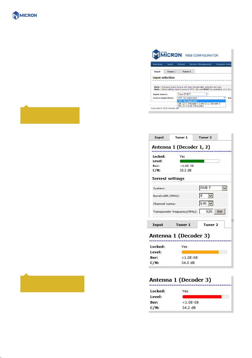
As the MyM Pro MICRON contains ”multituner” start by
selecting either DVB-T/T2, DVB-S/S2, DVB-C or IP input.
After that you choose [Tuner 1] or/and [Tuner 2] for
settings of the tuner parameters also depending on choice
of [Source duplication] that can be either OFF or ON with
both CI used or ON with only one CI chosen for both Ch1,
Ch2 and Ch3 out.
5.2.1 DVB-T/T2 RECEPTION
For receiving from terrestrial, start with chosing Tuner
DVB-T/T2 as [Input source]. Tuner 1 provides the service list
for RF output Ch1 and Ch2. Tuner 2 provides the service
list for RF output Ch3. The tuner can also be ”Disabled”.
[Bandwidth] can be selected between 6, 7 or 8 MHz.
Select input channel from [Channel name] scroll list or
write the center frequency of the wanted Mux and press
[Set]. You can see if Tuner is locked. [Level] shall show a
green bar to be correct. If the bar is Orange or Red the
input level is out of recommended window (too low or too
high).
If you have an MyM Pro MICRON 6 proceed with next two
tuners [Tuner 3] and [Tuner 4] after moving the TP cable to
the other RJ 45 port (if not using switch). Tuner 3 provides
the service list for RF output Ch4 and Ch5. Tuner 4
provides the service list for RF output Ch6.
With source duplication
ON, only Tuner 1 is in use.
Do not press [Set] if channel
is chosen from the scroll list
CLOSE TO LIMIT
OVER LIMIT

MENUES AND SETTINGS 10
5.2.2 DVB-S/S2 RECEPTION
For receiving from satellite, start with chosing Tuner
DVB-S/S2 as [Input source].Tuner 1 provides the service list
for RF output Ch1 and Ch2. Tuner 2 provides the service
list for RF output Ch3 when Source duplication is chosen
as OFF.
Select the actual Input parameters for the satellite
transponder you receive.After the tuner has locked you
can read the values for [Locked], [Level] and [C/N].
[Level] shall show a green bar to be correct. If the bar
is Orange or Red the input level is out of recommended
window (too low or too high).
If you have an MyM Pro MICRON 6 proceed with next two
tuners [Tuner 3] and [Tuner 4] after moving the TP cable to
the other RJ 45 port (if not using switch). Tuner 3 provides
the service list for RF output 4 and 5. Tuner 4 provides the
service list for RF output 6.
5.2.3 DVB-C RECEPTION
For receiving from cable, start with choosing Tuner DVB-C
as [Input source].Tuner 1 provides the service list for RF
output Ch1 and Ch2. Tuner 2 provides the service list for
RF output Ch3 when Source duplication is chosen as OFF.
With source duplication
ON, only Tuner 1 is in use.
With source duplication
ON, only Tuner 1 is in use.

MENUES AND SETTINGS 11
Select the actual Input parameters for the QAM signal you
receive.After the tuner has locked you can read the values
for [Locked], [Level] and [C/N].
[Level] shall show a green bar to be correct. If the bar
is Orange or Red the input level is out of recommended
window (too low or too high).
If you have an MyM Pro MICRON 6 proceed with next two
tuners [Tuner 3] and [Tuner 4] after moving the TP cable to
the other RJ 45 port (if not using switch). Tuner 3 provides
the service list for RF output 4 and 5. Tuner 4 provides the
service list for RF output 6.
5.2.4 IPTV RECEPTION
For receiving from IPTV, start with chosing IPTV as [Input
source].With this Input the Source duplication is ON, and
only CI 1 is used for decryption of 1 MPTS input or 3 SPTS’s
input.
Select the actual Input parameters for the IPTV signal you receive. You can receive either one MPTS or
three SPTS’s. After saving, you can see information of the received IPTV signal(s).
Decryption of SPTS’s
is only working if
only one CAT is used.

MENUES AND SETTINGS 12
5.3 OUTPUT SETTINGS
5.3.1 MODULATION
BAND
Start the output setup by selecting which band you want to use. You can select [VHF-7/8 CCIR], [VHF-8
OIR] , [UHF-7 CCIR] or [UHF-8]. After selection press [Set].
FREQUENCY
For each of the 3 (or 6) possible RF output channels, set the
desired output channels by using [Channel name] scroll list
or write the frequency.
[Modulator enabled] can be set to “OFF” to switch off the
RF out.
There is receiving information of Running status, ONID, TSID and SID
for each Modulator/Decoder after that Services has been selected in
the Service management.
If only A/V out shall be used one
must first set Modulator to ON to be
able to do decoder settings and after
that Modulators can be switched OFF.
The MyM Pro MICRON
provides DSB modulation
so you can’t use adjacent
channels.

MENUES AND SETTINGS 13
5.3.2 DECODER SETTINGS
VIDEO STANDARD
Selection possible to made according to scroll list.
VIDEO CONVERSION
Ignore will give the same format out as in the received transmission.Letterbox gives correct picture
format both on 16:9 and 4:3 TV set’s.Pan & scan and Forced will crop the picture in horizontal direction.
Combined will crop both in horizontal and in vertical direction.
WSS CONFIGURATION
Setting for this is depending on what settings connected TV set’s have. Setting of WSS is also depending
on setting of [Video conversion].
AUDIO LANGUAGE
Select which language to receive and transmit on the outgoing programs.
PREFFERED AUDIO TYPE
If both AC-3 (Dolby) and MPEG-1 or MPEG-2/HE-AAC sound is transmitted one can choose what type
that shall be prio 1.
A/V AUDIO LEVEL
This setting allows to equalise the difference in sound level between different programs. Settings can be
done between +6 and -6 dB for the audio outputs on back panel.
Reboot is needed after
change of Video Standard

MENUES AND SETTINGS 14
SUBTITLING
Subtitling can be switched ON/OFF and with subtitling
ON, there is a choice for DVB/Teletext [Priority]. If same
language
[Type] can be chosen as Normal or Hearing impaired.
[Codepage] can be changed for different character set.
[Language] can be chosen between languages that is
in the received PMT. If there is no subtitling only “None”
will be present.
[Subtitle configuration] have the different choice:
None, Auto, In picture and Out of picture.
5.3.3 DECODER STATUS
Shows status of Video, Audio, Servicename and SID and
Subtitling.
5.3.4 MODULATOR SETTINGS
In this menu you can do settings for [TV Standard], [Test
lines], [Audio System] and [Audio level].
Always click on Save after changes
are made. Sometimes a reboot is
required to start the subtitling process
Audio level is not
subcarrier level.

MENUES AND SETTINGS 15
5.4 SERVICE MANAGEMENT
The MyM Pro MICRON 3 contains two and for MyM Pro MICRON 6 four separate tuners and totally
3 or 6 services can be selected for each of the output channels, named [D-1], [D-2] and [D-3] and for
MyM Pro MICRON 6 also [D-4], [D-5] and [D-6].
The list of services presents all received services from both tuner inputs. Service from Tuner 1 is named
“Tuner 1” and services from Tuner 2 is named “Tuner 2” respectively “Tuner 3” and “Tuner 4” in a
MyM Pro MICRON 6.
When one program (service) is selected, the box in front of the program name changes colour to
green. Also the Name of the service will come green when decoding is running for both Audio and
Video. The service list gives following information:
Green colour indication
Shows type of service (MPEG-2, MPEG-4, Data etc.).
Program name.
Name of operator.
Indicates what tuner input the service is received from.
Shows what CI slot that is used for the service.
Service ID number (as received).
Shows if a CAM is inserted.
Selected service
Type
Name
Provider
Input
CI-slot
SID
Status
To detect whether a Common Interface module and smart card actually
decrypts the programs this can be done by monitor the colour of the Name
of the chosen service that will be RED until decryption works and than
turn to GREEN. Both video and audio must be OK for GREEN indication!

MENUES AND SETTINGS 16
5.5 CI MENU
The MyM Pro MICRON 3 contains 2 CI (Common Interface)
and MyM Pro MICRON 6 contains 4 CI (Common
interface). [CI-1] decrypts services for output D-1 and D-2
and also for D-3 if [Source duplication], “ON, CI1 to all 3
decoders” in the Input menu is chosen . The [CI-2] decrypt
services for output D-3 in Source duplication mode OFF
and “ON, CI1 to D1 and D2 and CI 2 to D3”.
In MyM Pro MICRON 6 [CI-3] decrypt services for output
D-4 and D-5 and also for D-6 if [Source duplication], “ON,
CI3 to all 3 decoders” in the Input menu is chosen. The
[CI-4] decrypt services for outputD-6.In menu you get
information about CAM and card.
In the Advanced settings menu you can change timing
settings for the used CAM if there is a need for changing
that. After a change is made the [Save] button must be
clicked. If changes are made and does not work, you can
get the default settings again by a click on the [Restore
defaults] button and a click on the [Save settings] button.
NOTE 1: Change in this menu is ONLY for advanced users.
NOTE 2: If one change CAM to another CA system (i.e. from NDS to Conax) the unit needs to be
rebooted. Decryption may take some seconds before it starts.
NOTE 3: For timeshare channels it might be necessary to change settings for “update”,“add” command
or timings.
5.6 SYSTEM OPTIONS
UPGRADE
The Upgrade menu is used to be able to download
software Upgrades or future software functionality.
The procedure of downloading a new software shall be
done as in “Upgrade instructions” because that could change from one to another FW version.
The Upgrade menu shows current files downloaded into the units and can be useful when contacting
WISI support.

MENUES AND SETTINGS 17
UPTIME
The Uptime menu gives statistics of uptime and possible
restarts. The log can be cleared by click on [Clear log].
NETWORKING
This section shows current IP-address, Netmask and
Gateway settings.
Remember to change settings if the default IP address
is used by other devices in your network. There is also
settings for [DNS Servers]. Settings for [DNS Servers] must
be done if NTP server is used as Time source.
IGMP setting shall be same as used in network (IP in use).
In case you have forgotten your IP-address please consult
the WISI support web site and download free of charge
our tool “IP-supporter”(can be downloaded from www.
wisi.se).
This tool finds all MyM Pro MICRON and their respective IP addresses available in your network.
Click on [Save] after changes are made.
DATE/TIME
In this menu there are settings for [Time zone], used source for TDT and settings for [NTP Server]. By
clicking on Enable/Disable icon one can change the used Time source for TDT (and TOT if present in the
received TS).
To get correct restart date
and time, make sure that
settings in Date &Time
menu are correct
If NTP server is used, DNS
server address must be chosen
in Networking menu

MENUES AND SETTINGS 18
MAINTENANCE
In maintenance menu you can store a backup fíle of the configuration in the MyM Pro MICRON by click
on [Backup] that can be useful if unit has to be swapped or if multiple installations are made with the
same settings. Use [Browse] and [Restore] for upload of a saved backup file.[Factory reset] can be made.
There is a click button for [Restart] of the unit via the web interface.

INSTALLATION & CONFIGURATION 19
6. INSTALLATION & CONFIGURATION
The MyM Pro MICRON can be installed either as a stand alone unit directly on the wall by the use of a
dedicated MyM Pro MICRON Wall Mount brackets (part number 702800.10) or in an 19 inch cabinet.
Before connecting power to the MyM Pro MICRON, make sure that all other connections have been
made. A coaxial cable of good quality with an F-connector should be connected to the Antenna input
and another one from the RF output to the SMATV network.
Make all necessary settings as described in section 4 and 5.
ACCESSORIES
INSTALLATION WITH MYM PRO MICRON 3
WALL MOUNT KIT 1 UNIT.
MyM Pro MICRON Wall Mount kit 1 unit
including screws and nuts
Art no: 121401.10
MyM Pro MICRON Wall Mount kit 3 units (for
two MyM and one switch) including screws
and nuts.
Art no: 121403.10

TECHNICAL SPECIFICATION 20
7. TECHNICAL SPECIFICATION
Miscellaneous
Setup Web based GUI
Operating temperature 0 to +45°C non condensing
Dimensions 383x220x44 mm (excluding connectors)
Weight
MyM Pro MICRON 3
Approximately 2.6 kg
MyM Pro MICRON 6
Approximately 3.2 kg
Power requirements
Power supply 94-264VAC, 50/60 Hz
MyM Pro MICRON 3 Power consumption Typ. 18 W
Single Europlug (CEE 7/16)
MyM Pro MICRON 6
Power consumption Typ. 36 W
Dual Europlug (CEE 7/16)
Split power supply design, not fully
redundant. Three output channels
operate per plug.
RF Modulators
Number of modulators
MyM Pro MICRON 3
3 output channels
MyM Pro MICRON 6
6 output channels
Modulation standards PAL B/G, I, D/K, SECAM, Double side band
Modulation audio FM mono, NICAM stereo, A2/A2* stereo
Channel frequency 160 – 862 MHz
Connectors
MyM Pro MICRON 3
1 Type F female, 75 Ω connector
MyM Pro MICRON 6
2 Type F female, 75 Ω connectors
Level Typ. 80 dBμV, fixed
Decryption interfaces
MyM Pro MICRON 3 2 Common Interface slots
MyM Pro MICRON 6 4 Common Interface slots
Multidecryption Yes
DVB-S /S2 Satellite Receivers
Input frequency 925 – 2175 MHz
Input level -65 to -25 dBm
Symbol rates 1.0 – 45 Mbaud (max 100 Mbit/s)
Spectral inversion Yes, selectable
LNB voltage Auto, Off or 13/18V, programmable
22kHz to LNB Auto, On or Off, programmable
DVB compliance DVB-S (EN 300 421)
DVB-S2 (EN 302 307)
DiSEqC Supporting control of up to 4 sat. sources
*) Available modes as described adjacently.
Multi Standard Tuners
MyM Pro MICRON 3 2 individually selectable tuners*
2 Type F female, 75 Ω connectors
MyM Pro MICRON 6 4 individually selectable tuners*
4 Type F female, 75 Ω connectors
DVB-T/T2 Terrestrial Receivers
Input frequency 43 –1002 MHz
Input level (DVB-T) -70 to -30 dBm 1)
Input level (DVB-T2) -70 to -30 dBm 2)
Bandwidth (DVB-T) 6 / 7 / 8 MHz
Bandwidth (DVB-T2) 5 / 6 / 7 / 8 MHz
DVB compliance DVB-T (EN 300 744)
DVB-T2 (ETSI EN 302 755)
1) QEF reception with test signal: 8k, 64 QAM, ¼ guard interval, 2/3 FEC
2) QEF reception with test signal: 32K, 256-R QAM, 1/16 guard interval,
64k LPDC, code rate 2/3, PP4, BW-8MHz, SISO
DVB-C Cable Receivers
Input frequency 43 –1002 MHz
Input level -60 to -30 dBm 1)
Bandwidth 8 MHz
Symbol rate 1 – 7.2 Mbaud
DVB compliance DVB-C (EN 300 429 / ITU J.83 Annex A/C)
1) QEF reception with test signal: 64 QAM, C/N 26dB
IPTV Receivers
IPTS receiver interface
MyM Pro MICRON 3
1 IPTS receiver interface
MyM Pro MICRON 6
2 IPTS receiver interfaces
Connectors
MyM Pro MICRON 3
1 RJ45 10/100Base-T/Tx connector*
MyM Pro MICRON 6
2 RJ45 10/100Base-T/Tx connectors*
Capacity per receiver 1MPTS or 1- 6 SPTS(CBR or VBR)
Total capacity per receiver < 45 Mbit*
*) Shared with control. Simultaneous control traffic reduces the receiver
capacity correspondingly.
MPEG Decoder – Video /Audio
Supported formats
video
MPEG-2 MP@ML, MPEG-2 MP@HL,
up to MPEG-4 H.264 AVC, HiP level 4
Supported formats
audio
MPEG-1 layer II, HE-AAC,
Dolby Digital AC-3
Aspect Ratio Letterbox, Pan/Scan, or conversion
combined (14:9) programmable, WSS
Teletext Subtitling Teletext or DVB subtitling
Table of contents