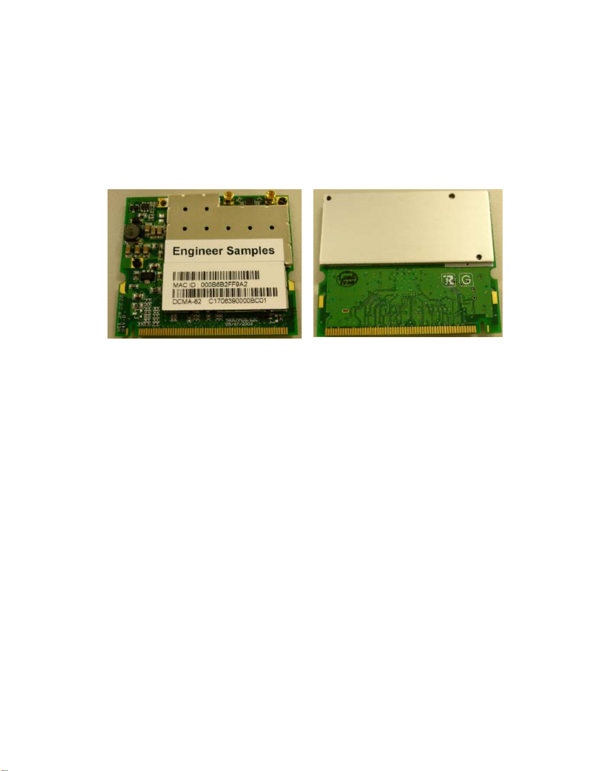
Wistron NeWeb DCMA82 User manual

WLAN 802.11a/b/g mini-PCI Module
User Manual
(DCMA-82)
Version: 1.0
Nov. 2006

1
Copyright Statement
No part of this publication may be reproduced, stored in a retrieval system, or
transmitted in any form or by any means, whether electronic, mechanical,
photocopying, recording or otherwise without the prior writing of the publisher.
Windows™98SE/2000/ME/XP are trademarks of Microsoft®Corp.
Pentium is trademark of Intel.
All copyright reserved.

2
DCMA-82 Compliances
Federal Communication Commission Interference Statement
ThisequipmenthasbeentestedandfoundtocomplywiththelimitsforaClassBdigitaldevice,
pursuanttoPart15oftheFCCRules.Theselimitsaredesignedtoprovidereasonableprotectionagainst
harmfulinterferenceinaresidentialinstallation.Thisequipmentgenerates,usesandcanradiateradio
frequencyenergyand,ifnotinstalledandusedinaccordancewiththeinstructions,maycauseharmful
interferencetoradiocommunications.However,thereisnoguaranteethatinterferencewillnotoccurin
aparticularinstallation.Ifthisequipmentdoescauseharmfulinterferencetoradioortelevision
reception,whichcanbedeterminedbyturningtheequipmentoffandon,theuserisencouragedtotry
tocorrecttheinterferencebyoneofthefollowingmeasures:
Reorientorrelocatethereceivingantenna
Increasetheseparationbetweentheequipmentandreceiver
Connecttheequipmentintoanoutletonacircuitdifferentfromthattowhichthereceiveris
connected
Consultthedealeroranexperiencedradio/TVtechnicianforhelp
FCC Caution:
Anychangesormodificationsnotexpresslyapprovedbythepartyresponsibleforcompliancecould
voidtheusersauthoritytooperatethisequipment.ThisdevicecomplieswithPart15oftheFCCRules.
Operationissubjecttothefollowingtwoconditions:
(1)Thisdevicemaynotcauseharmfulinterference,and
(2)Thisdevicemustacceptanyinterferencereceived,includinginterferencethatmaycauseundesired
operation.
IEEE802.11bor802.11goperationofthisproductintheU.S.A.isfirmware‐limitedtochannels1
through11.
IMPORTANT NOTE: FCC Radiation Exposure Statement:
ThisequipmentcomplieswithFCCradiationexposurelimitssetforthforanuncontrolledenvironment.
Thisequipmentshouldbeinstalledandoperatedwithminimumdistance20cmbetweentheradiator&
yourbody.Thistransmittermustnotbeco‐locatedoroperatinginconjunctionwithanyotherantenna
ortransmitter.Theavailabilityofsomespecificchannelsand/oroperationalfrequencybandsiscountry
dependentandisfirmwareprogrammedatthefactorytomatchtheintendeddestination.Thefirmware
settingisnotaccessiblebytheenduser.
Wireless 5 GHz Band Statements:
AstheAccessPointcanoperateinthe5150‐5250MHzfrequencybanditislimitedbytheFCCtoindoor
useonlysoastoreducethepotentialforharmfulinterferencetoco‐channelMobileSatellitesystems.
Highpowerradarsareallocatedasprimaryusers(meaningtheyhavepriority)ofthe5250‐5350MHz

3
and5650‐5850MHzbands.Theseradarscouldcauseinterferenceand/ordamagetotheaccesspoint
whenusedinCanada.
Wireless 4.9 GHz Band Statements: (please refer to Appendix B for detailed
limitation)
Installation and operation requires an approved license from the FCC.
This device is intended only for OEM integrators under the following
conditions:
1) Theantennamustbeinstalledsuchthat20cmismaintainedbetweentheantenna
andusers,and
2) Thetransmittermodulemaynotbeco‐locatedwithanyothertransmitteror
antenna,
3) ForallproductsmarketinUS,OEMhastolimittheoperationchannelsinCH1to
CH11for2.4Gbandsbysuppliedfirmwareprogrammingtool.OEMshallnot
supplyanytoolorinfototheend‐userregardingtoRegulatoryDomainchange.
4) DuetotheinvolvementofFCCpart90(Y)4.9Gsafetybandoperation,theend
productmustbeprofessionalinstalledandcannotbemarketedtothegeneral
public.
Aslongas4conditionsabovearemet,furthertransmittertestwillnotberequired.However,theOEM
integratorisstillresponsiblefortestingtheirend‐productforanyadditionalcompliancerequirements
requiredwiththismoduleinstalled(forexample,digitaldeviceemissions,PCperipheralrequirements,
etc.).
IMPORTANT NOTE:
Intheeventthattheseconditionscannotbemet(forexamplecertainlaptopconfigurationsor
co‐locationwithanothertransmitter),thentheFCCauthorizationisnolongerconsideredvalidandthe
FCCIDcannotbeusedonthefinalproduct.Inthesecircumstances,theOEMintegratorwillbe
responsibleforre‐evaluatingtheendproduct(includingthetransmitter)andobtainingaseparateFCC
authorization.
End Product Labeling
Thistransmittermoduleisauthorizedonlyforuseindevicewheretheantennamaybeinstalledsuch
that20cmmaybemaintainedbetweentheantennaandusers.Thefinalendproductmustbelabeledin
avisibleareawiththefollowing:“ContainsFCCID: NKRDCMA82”.
Manual Information To the End User
TheOEMintegratorhastobeawarenottoprovideinformationtotheenduser
regardinghowtoinstallorremovethisRFmoduleintheuser’smanualoftheend
productthatintegratesthismodule.Theendusermanualshallincludeall
requiredregulatoryinformation/warningasshowinthismanual.

4

5
Table of Contents
1. INTRODUCTION 6
1.1 SYSTEM REQUIREMENTS.........................................................................................6
1.2 FEATURES.................................................................................................................6
2. DRIVER/UTILITY INSTALLATION / UNINSTALLATION 7
2.1 INSTALLATION..........................................................................................................7
2.2ADDITIONALSETUP PROCESSES............................................................................10
2.3 UNINSTALLATION...................................................................................................11
3. CONNECTING TOAN EXISTING NETWORK 12
4. CREATINGAN AD HOC NEW NETWORK 17
5. MODIFYINGAWIRELESS NETWORK 20
5.1 INFRASTRUCTURE MODEAND AD HOC MODE.....................................................20
5.2 MODIFYINGAWIRELESS NETWORK.....................................................................21
5.3 DEFAULT SETTINGS WINDOWS XPZERO-CONFIGURATION................................28
5.4 SUPERA/GSETTING..............................................................................................28
APPENDIX A: FAQ ABOUT WLAN 29
SPECIFICATION 31
APPENDIX B: Wireless 4.9GHz Band Statements 35
Notes: Professional Installation Guidelines 42

6
1. Introduction
Thank you for purchasing the WLAN 802.11a/b/g mini-PCI Module that provides the
easiest way to wireless networking. This User Manual contains detailed instructions in
the operation of this product. Please keep this manual for future reference.
1.1 System Requirements
A laptop PC contains:
-32 MB memory or greater
-300 MHz processor or higher
Microsoft®Win™2000/ME/98 Second Edition/XP
1.2 Features
Mini-PCI adapter, half size design
IEEE 802.11a/b/g compatible: allowing inter-operation among multiple
vendors
Support Atheros Super A/GTM Mode
Provide seamless roaming within the IEEE 802.11 a/b/g WLAN
infrastructure
Site survey function

7
2. Driver/Utility Installation / Uninstallation
2.1 Installation
Note! The Installation Section in this User Manual describes the first-time installation
for Windows. To re-install the driver, please first uninstall the previously
installed driver. See Chapter 2.3 “Uninstallation” in this User Manual.
Follow the steps below to complete the driver/utility installation:
1. Insert the Installation Software CD into the CD-Rom Drive.
2. Click “Next”.
3. Read the License Agreement and click “Yes”.

8
4. Click “Next” to continue or click “Browse” to choose a destination folder.
5. Click “Next”.
6. Click “Yes” to create a shortcut icon on your desktop.

9
7. Click “Finish”.
8. You should now see a shortcut icon on your desktop.

10
2.2 Additional Setup Processes
During software installation procedure, each operating system may prompt different
specific options:
1. Windows 98SE: The system will request the original Windows CD during the
installation process. When the installation is finished, you’ll have to restart your
computer.
2. Windows Me: Please restart your computer when the installation is finished.
3. Windows 2000/XP: Select “Install the software automatically” when the window
with this option appears, and then click “Next” to continue installation.

11
2.3 Uninstallation
Note! Before uninstallation, please close all running programs.
1. Click Start>Programs>WLAN a+b+g mini-PCI Module >UnInstall WLAN a+b+g
mini-PCI Module.
2. Choose “Remove”. Click “Next”.
3. Click “OK” to start Uninstall.
4. Click “Finish”. Uninstall is now completed.

12
3. Connecting to an Existing Network
1. Double click the shortcut icon of WLAN a+b+g mini-PCI Module on the desktop,
and the Configuration window appears.
2. Click on the Refresh button to list all available networks.

13
Note! To automatically connect to the network with the strongest signal, select
Enable Smart Selection. Any displays in Profile List.
3. From the list of “Available Networks”, choose one network by double clicking the
Network Name. One of the following dialog boxes appears. Click “Yes” to
continue.
4. If the chosen network has security enabled, the Security tab displays. Select the
security option used by the network. Contact the network administrator for the
correct settings.

14
5. If selecting WPA or 802.1X, select the EAP type, then click on the Configure
button to select the certificate.
6. If selecting WPA-PSK, click on the Configure button to enter the PassPhrase.

15
7. If selecting Pre-Shared Key, click on the Configure button to enter the correct
Encryption Keys.
Key entry method:
a.10hex digits: User must enter 10 hexadecimal digits.
The hexadecimal define is "0-9" and "A-F".
ex: 123456abc
b.5 chars: User must enter 5 characters. ex: ab3#@
c.13 chars: User must enter 13 characters.
ex: ab3#@kf08&kdk
d.16 chars: User must enter 16 characters.
ex: ab3#@kf08&kdk456
For WEP key, please contact with MIS administrator.
8. Click on OK (or Apply if using the other tabs) when done to save the settings.
9. Once connected (the icon or in front of the name of the Connected
Network), you can check the signal strength from the icon in the Windows
System Tray.

16
Additional Note for Windows XP
In Windows XP, it is recommended that you use the WLAN a+b+g mini-PCI Module
Configuration Utility. Before using the Utility, please follow the steps below to
disable the Windows XP Zero Configuration:
Option 1:
1. Double click the shortcut icon to open the Utility.
2. From the Windows System Tray, you should see the signal icon. Right-click it
and select “Disable Zero-Configuration”.
Option 2:
1. Go to “Control Panel” and double click “Network Connections”.
2. Right-click “Wireless Network Connection” of “WLAN a+b+g mini-PCI Module”,
and select “Properties”.
3. Select “Wireless Networks” tab, and uncheck the check box of “Use Windows to
configure my wireless network settings”, and then click “OK”.

17
4. Creating an Ad Hoc New Network
1. In the Configuration window, click New .
2. Select the “Profile Editor” tab.

18
3. Choose the check box of Enable Advanced Setting to edit all settings.
4. If joining or creating an Ad-Hoc network, choose Ad Hoc.
5. If the correct country is not selected, select the country where the computer is
located.
ALERT! Different countries have different regulations that affect which channels
can be used. You should always choose the country where you are physically
located to avoid using an illegal channel.
6. Click OK (or Apply if using the other tabs) to save the settings.
For details of each setting, refer to Modifying a Wireless Network on page 20.
7. Click the Security tab. If not using security, select None.
8. If security is used, select Pre-Shared Key and click on the Configure button.

19
9. Enter an encryption key in the Shared: First field.
10. Click OK (or Apply if using the other tabs) to save the settings. The new
Network Name is listed in the Profile List.
The driver does not allow channel selection in Ad-Hoc mode. Instead, the driver
starts with an initial channel then checks channel status. If the channel is busy, the
driver automatically uses a different channel.
For details of each setting, please see chapter 5.
Table of contents
Other Wistron NeWeb PCI Card manuals