Ergo S-1 OE – Assembly Instructions
Wizard Keyboards 1
Table of Contents
1. What You’ll Need .............................................................................................................................. 2
2. Compatibility ..................................................................................................................................... 2
2.1. Switch / Keycap Compatibility ..................................................................................................... 2
2.2. Insulated Wire ............................................................................................................................. 2
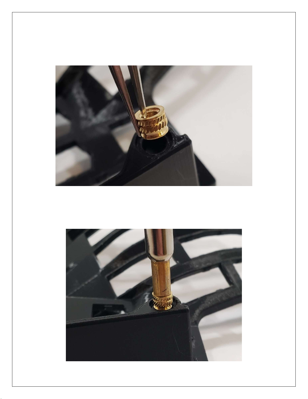
3. Heat Set Inserts ................................................................................................................................ 3
Figure 1 - Insert Orientation ............................................................................................................ 3
Figure 2 - Insert Tool ...................................................................................................................... 3
Figure 3 - Insert Installation Example ............................................................................................. 4
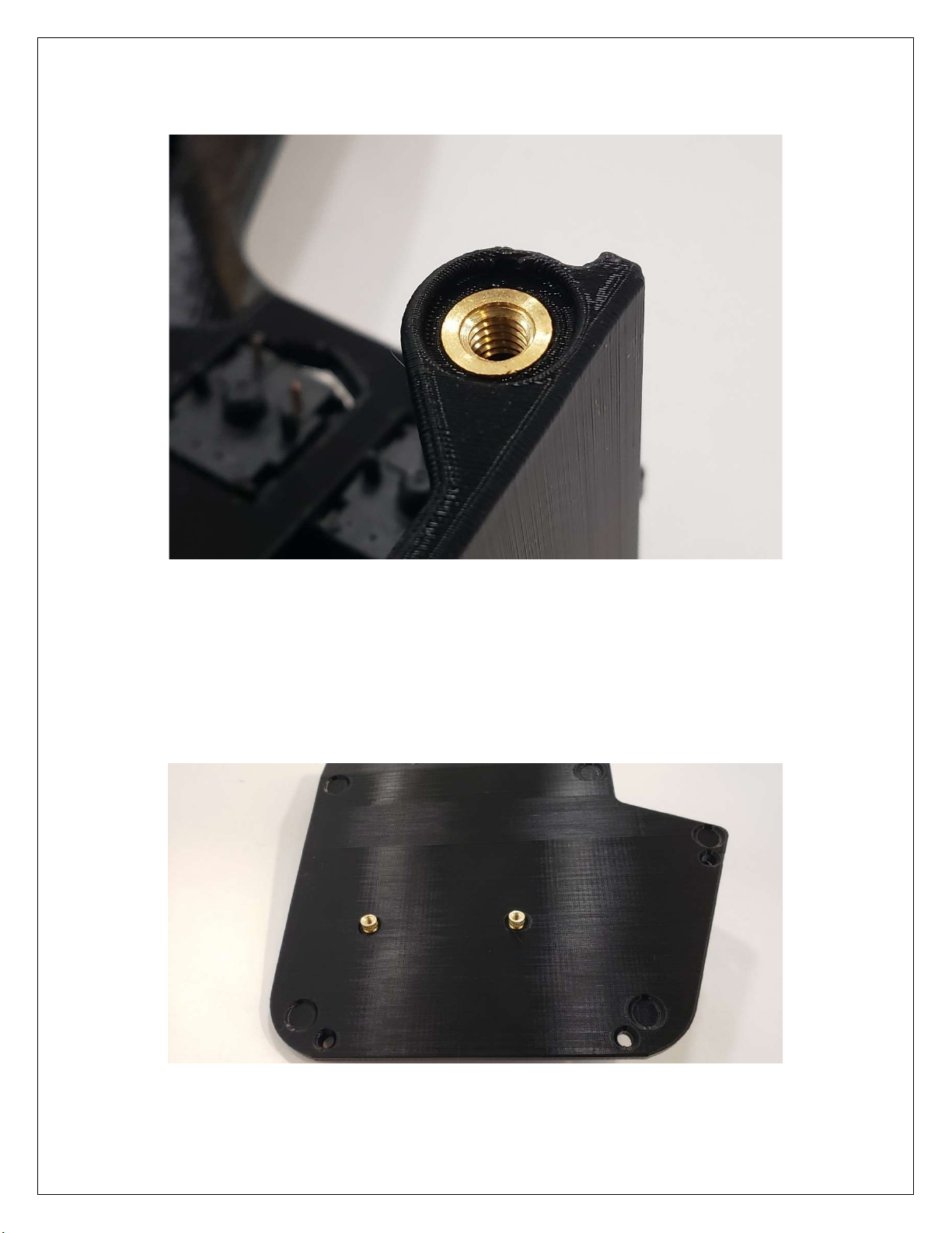
Figure 4 - Base Inserts ................................................................................................................... 4
Figure 5 - Ramp Installed ............................................................................................................... 5
4. Switches ............................................................................................................................................ 5
Figure 6 - Switch Orientation Front ................................................................................................. 5
Figure 7 - Switch Orientation Rear ................................................................................................. 6
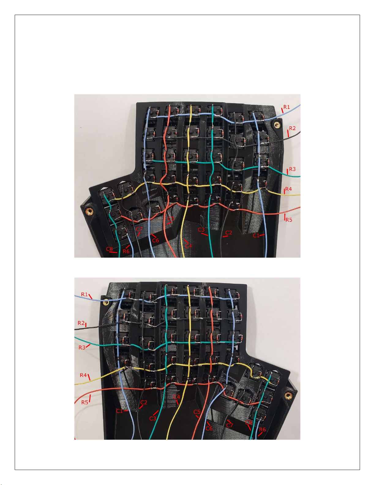
5. Switch Matrix Wiring ......................................................................................................................... 6
Figure 8 - Diode Orientation ........................................................................................................... 6
Figure 9 - Diode Orientation Close Up............................................................................................ 6
Figure 10 - Left Case Switch Matrix ............................................................................................... 7
Figure 11 - Right Case Switch Matrix ............................................................................................. 7
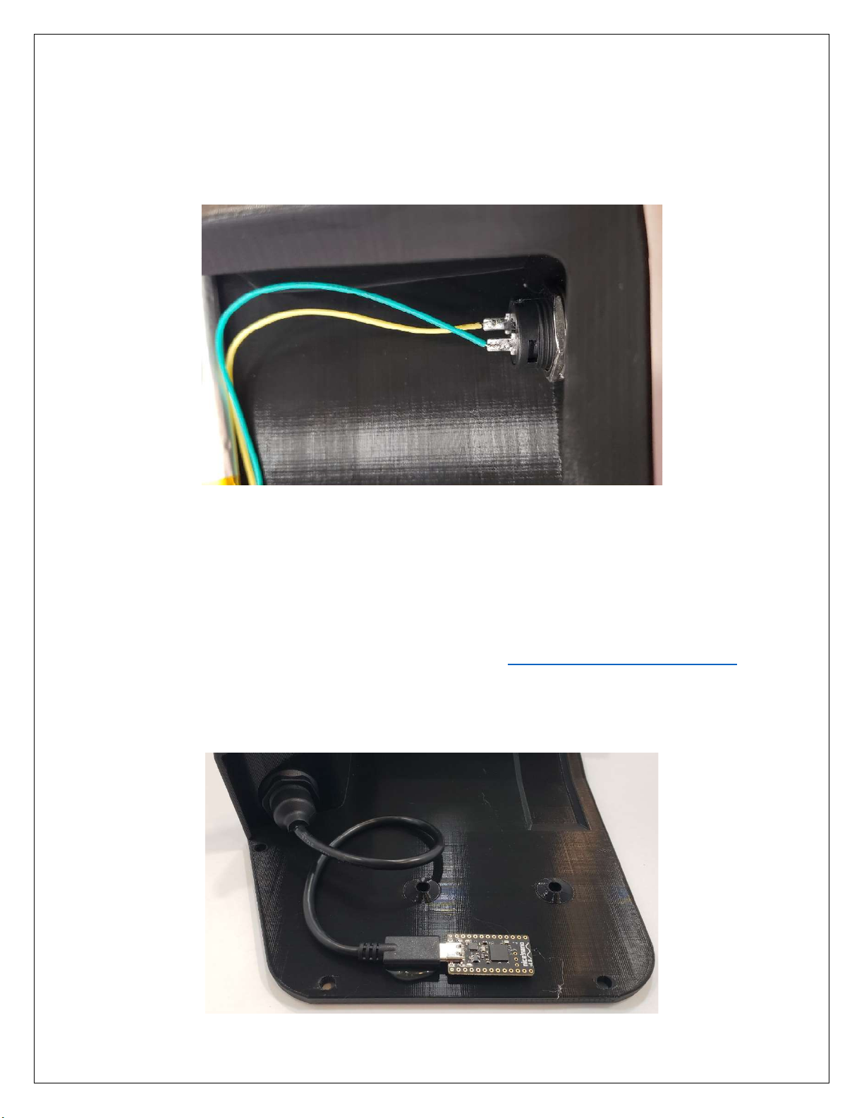
6. Reset Switch ..................................................................................................................................... 8
Figure 12 - Reset Switch ................................................................................................................ 8
7. Microcontroller .................................................................................................................................. 8
Figure 13 - Microcontroller Location ............................................................................................... 8
7.1. Microcontroller Wiring ................................................................................................................. 9
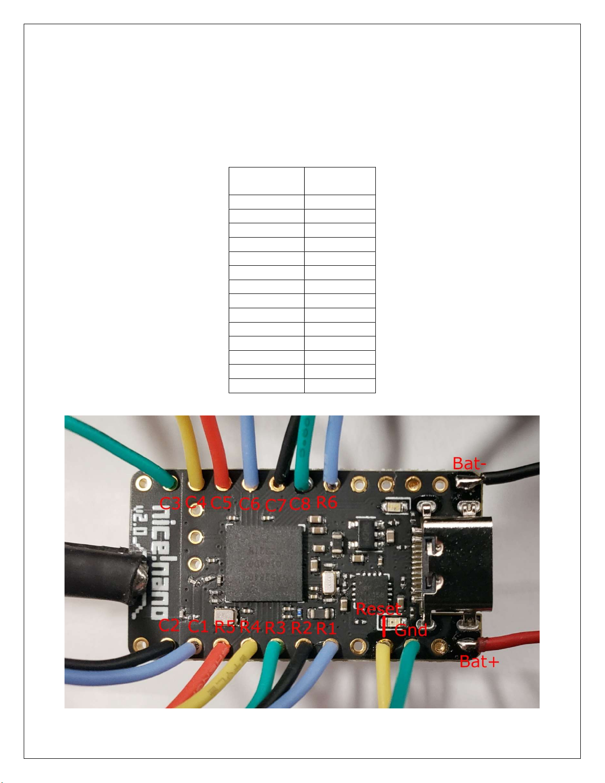
Table 1 - Matrix Positions / Pin Labels ........................................................................................... 9
Figure 14 - Nice!Nano Wiring ......................................................................................................... 9
8. Battery............................................................................................................................................. 10
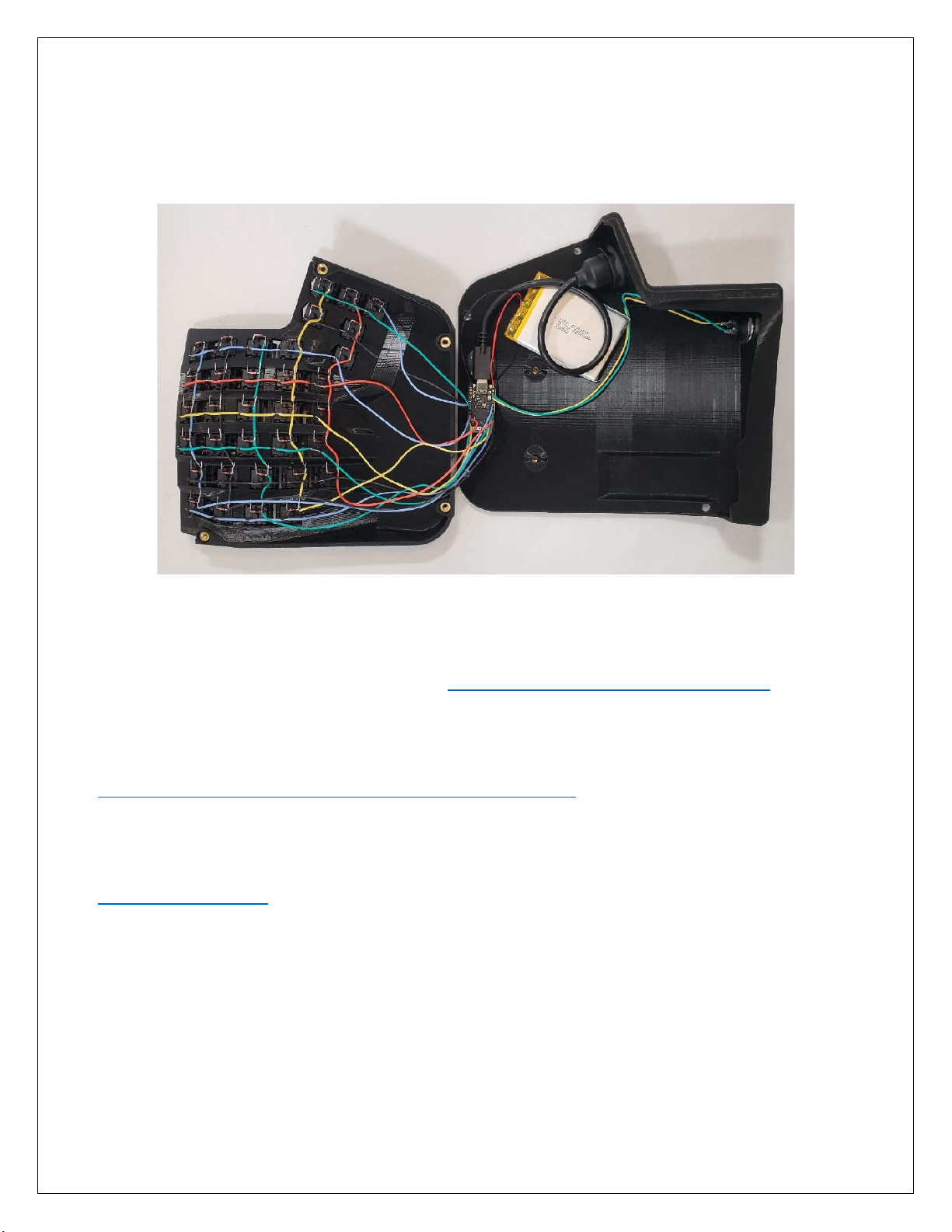
Figure 15 - Battery Location ......................................................................................................... 10
9. Firmware ......................................................................................................................................... 10