WolfPack 9x9 Card Cage User manual

1
WolfPack Card Cage Matrix Switcher Series
User Manual

2
Version: V1.0.1

3
Preface
We are honored for your purchasing of our products. To have the best performance of
the products, please read the user manual carefully before using them. Hope this user
manual can bring more convenience, and please don’t hesitate to get in touch with us
or your local dealer if you have any issue during your usage.
Note: This user manual is for 9x9 matrix switch, 18x18 and 36x36 also can reference
this user manual as well.

4
To protect the device and operating personnel from electrostatic discharge, you
need to check and ensure that the device is grounding well before the device is
powered on. Please observe the following when you install, use, maintain this
equipment.
SAFETY

5
Attention the equipment needs good earth grounded
➢Please use single-phase three wire system AC 220V power supply, and ensure all
transmission system is grounding well.
➢To protect operating personnel and the device,please turn off all power supplies and
pull the plug before moving the device or doing some specific works which need to be
done when the electricity is turned off. Please turn off the main power switch on rainy
days or when not in use for a long time.
➢Please do not put anything upon the cables, or tread the cables.
➢To avoid damaging the device, please turn off power supply before plugging cable
into the device or pulling cable from device. The damage caused by plugging/ pulling
cables without turning off power supply is outside the scope of the warranty.
➢The power of the device gives out heat when it works, so it’s necessary to keep the
work environment ventilated to protect the device from the damage caused by over
temperature.
➢Do not place the device in very cold or very hot places. Do not sprinkle any corrosive
chemicals or liquid on or around the device.
➢To avoid accident or any further damage, non-professionals please do not dismantle
or maintain the device without permission.

6
Contents
1. Product Introduction .............................................................................................................. 4
2. Product Features .....................................................................................................................4
3. Technical Datasheet ............................................................................................................... 5
4. Packing Datials ........................................................................................................................ 5
5. Panel diagram ...........................................................................................................................5
6. Product Connection Diagram .............................................................................................. 7
7. Product Operation and Instruction .................................................................................... 7
7.1 Front Panel Switching Operation ...............................................................................7
7.1.1 Switch ................................................................................................................... 7
7.1.2 Scene ....................................................................................................................7
7.1.3 Set Up.....................................................................................................................8
7.1.4 View .......................................................................................................................8
7.2 WEB Control ...................................................................................................................8
7.2.1 Login ..................................................................................................................... 8
7.2.2 Switch ................................................................................................................... 8
7.2.3 Scene ....................................................................................................................9
7.2.4 Rename ..............................................................................................................15
7.2.5 centralization Control ......................................................................................10
7.2.6 Set Up .................................................................................................................18
7.2.7 Upgrade ............................................................................................................. 20
7.3 APP Control .................................................................................................................... 8
7.4 Control Commands.......................................................................................................21

7
8. Trouble Shooting and Attention ........................................................................................18
9. After Sales ...............................................................................................................................18
9.1 Warranty.......................................................................................................................... 19
9.2 limitation and Exception ............................................................................................ 19
Attachment A: Mini Modular Matrix input/output cards ............................................ 20
Attachment B: Matching Extender .................................................................................... 21
B1. HDBaseT Extender .....................................................................................................19
B2. Fiber Optic Extender ..................................................................................................29
1. Product Introduction
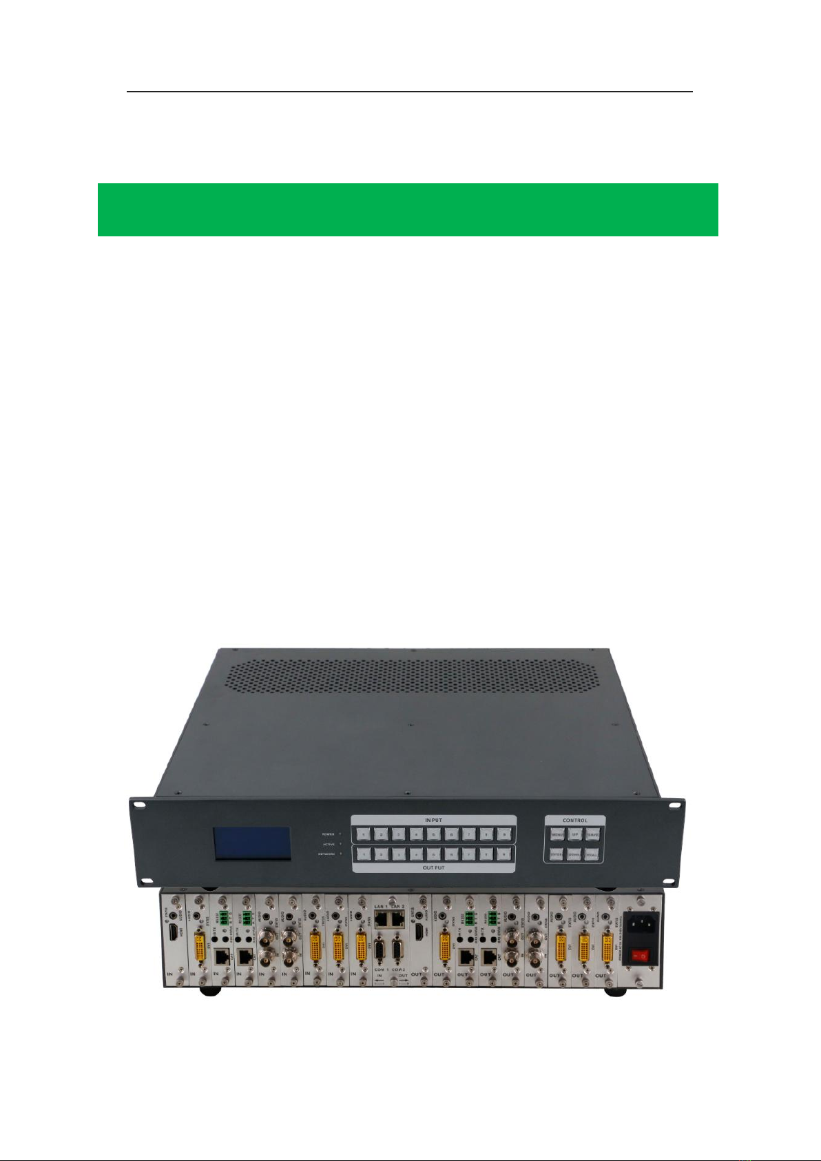
Mini chassis series Matrix switch is the newest Mini Type multifunction modular matrix,
with modular designing, plus the audio de-embedding, video extension, splitting, switching
function. With buttons management designing, there are 3 models: Mini99 supports 9x9,
Mini1818 supports 18x18, Mini3636 support 36x36. All the signal input and output cards
using 1-card 1-port, provides the most flexible configuration ability for users, with the
universal card can reach any switching, converting, extension, resolution adjustment
between CVBS / YPbPr / VGA / HDM I/ DVI with different connectors, supports 4K, EDID,
HDCP automatic adaptation and resolving, supports seamless fast switching function,
using dual control system designing, can connect with 2 different control systems. With
electromagnetic protection designing, it can efficiently shield the electromagnetic
interference for the surrounding environment to make sure the equipment running more
stable.
The single channel signal switching speed of the Mini modular matrix switch can reach
12.5Gbps, the main board is using Four core four links processing technology, the
switching ability speed can reach 32Gbps. With uncompressed transmission way for the
digital signal to make sure the image High fidelity output. Unique signal links shielding
designing technology to make sure the signal completeness, the internal data switch has
super strong capacity of resisting disturbance and long continuous and stable working
ability. With newest and advance algorithm to make sure the efficient instantaneity. Users
can choose the CVBS / YPbPr / VGA / HDMI / DVI / SD-HD-3GSDI / HDBaseT/ Fiber and
so on signal as input or output, to realize large number configuration, flexible card cage

8
designing, modular chassis. With unique processing way, it improves the switching speed
and realize no waiting between different control commands and seamless switching.
Complete designing perfectly solves the video system has too many sources and the
compatibility between the analog and the digital signal. And maximum reducing the costs,
it’s better for system upgrading, extension and maintenance. Overvoltage protection and
ESD anti-static etc technology protection procedures, to avoid the external impact.
Supports power down status protection, restart automatic recovery function. Meanwhile it
can support strong HDBaseT and Ethernet extension and management ability. Support
7*24 continuous operation. Support dual LAN and RS232 backup control, it’s convenient
for users to control via PC, central control and other remote-control equipment.
Mini modular matrix switch widely used in HD visual conferencing, radio and television
project, multimedia conferencing hall, large screen display project, television teaching,
command control center and so on.
2. Product Features
Modular designing, 1-card 1-port designing, can support CVBS/ VGA/ YPBPR/ DVI/
HDMI/ HDSDI/ 3GSDI/ HDBaseT/ Fiber all signal mixing input and output
Support seamless switching between all the signals
Strong signal switch processing ability, with 4 cores 4 links chip, the processing speed can
reach 32Gbps
Broadcasting professional with light button designing, easier for users to do the switching,
setup and so on function.
Support EDID automatic recognition and compatible with HDCP
Support all video signal stereo audio de-embedded, splitting and switching
Support 4k/30, 4K60, HDMI2.0 444 digital HD video signal transmission and seamless
switching
Support 3D image frequency repairing, close to pixel reread processing and 3D wipe off
interlacing processing function
Support scale up/down the frequency processing, close to pixel repairing processing and
fuzzy processing function
Support dual LAN backup control function, and realize the maximum centralization
network management function.
Support hot-plug function
Support power down scene auto saving protection function, restart auto recovery function

9
Support HDBaseT HD video signal converting and transmission function, to work with the
HDBaseT receiver/ transmitter, the distance can reach 70/ 100 meters (220/330 ft), and
the bandwidth can up to 10 Gbps
Support fiber optic input and output, the distance can reach 2,000~10,000
meters(6561~32808ft), the maximum can reach 80,000 meters(262,467ft)
Embedded strong WEB server, can realize remote network control and management
Support strong network centralization control function, one signal control interface can
reach 254 matrices switch system
Support over voltage, current, heat and over loading protection, it can efficiently reduce
the defective rates
3. Technical Datasheet
Model
9x9 Card Cage
18x18 Card Cage
36x36 Card Cage
Description
Mini99 modular
universal matrix
switch
Mini1818 modular
universal matrix switch
Mini3636 modular universal
matrix switch
Card Slots
9 slots for each,
1-card 1-port
18 slots for each, 1-card
1-port
36 slots for each, 1-card 1-port
Input Card
1-card 1-port, support HDMI, DVI, 3GSDI, VGA, YPBPR, CVBS, HDBaseT, Fiber
Optic
Output Card
1-card 1-port, support HDMI, DVI, 3GSDI, VGA, YPBPR, CVBS, HDBaseT, Fiber
Optic
Protocol
HDMI1.4a/ HDMI2.0, DVI1.0, compatible with HDCP and EDID function
Color Space
RGB444, YUV444, YUV422, support x.v. Color extension color gamut standard
Resolution
640x480---1920x1200@60Hz(VESA), 480i---4K30Hz(HDTV), 4K60Hz
Data Speed
12.5Gbps
Transmission
distance
70/ 100m(Cat6), 2000m(multi-mode), 80Km(Single-mode), 25m(Digital cable),
30m(Analog cable)
Control
Methods
Broadcasting switching button, dual RS232+LAN control
Dimension
482*390*88(2U)mm
482*390*178(4U)mm
482*390*355(8U)mm
Weight
6KG(No cards)
12.5KG(No cards)
25KG(No cards)

10
4. Packing Details
Mini modular universal Matrix switch.........................................1 unit
Power cord...................................................................................2 pcs
User manual.................................................................................1 pcs
5. Panel Diagram
Front Panel
1LCD display screen, for the equipment current operation status
2LED indicator
3POWER: power indicator, it will light up after power on, it will light off after
power off
4ACTIVE: switching indicator, it will flash while using the buttons/ WEB switching
successfully
5NETWORK: LAN control indicator, it will flash while using the WEB control
operation
6INPUT: input buttons, broadcasting with light button, from 1~9 input buttons
7OUTPUT: output buttons, broadcasting with light button, from 1~9 output buttons
8CONTROL:
MENU: menu button, it can recycling select the View, Switch, Scene Save/
Recall and Setup functions
Consumption
17W(No cards)
21W(No cards)
30W(No cards)
Power Supply
AC 110V-240V 50/60HZ
Working Temp
-10℃- 50℃
Storage Temp
-25℃- 55℃

11
UP: Up button
SAVE: Save button for saving the scene
ENTER: enter button
DOWN: down button
RECALL: Reload button for reloading/ recalling the saved scene
Rear Panel:
1) Rack ear for mounting on the 19inch rack
2) 3.5mm auto adaption audio input, it can switch automatically to 3.5mm audio
input while the input sources are VBS/YPBPR/VGA/DVI
3) DVI-I input port, it can support DVI, HDMI, VGA, CVBS, YPbPr input with
different connectors
4) Input blank cover
5) Status indicator, it will light up while the cards power on
6) Input Area: it can support DVI, HDMI, VGA, CVBS, YPbPr, FIBER, HDBaseT
signals mixing input
7) LAN Control Port: dual LAN control, support 2 different control system with long
distance control
8) RS232 control port: dual serial control port, via RS232 cable connection control
9) 3.5mm auto adaption audio output
10) DVI-I output port, it can support DVI, HDMI, VGA, CVBS, YPbPr input with
different connectors
11) Output Area: it can support DVI, HDMI, VGA, CVBS, YPbPr, FIBER, HDBaseT
signals mixing input

12
12) Power supply AC 110V-240V 50/60Hz
13) Power OFF/ON switch
6. Equipment Connection Diagram
7. Equipment Operation and Instruction
The LCD display screen will light up after power and turned on. It shows the current
operation status, press MENU button, it will keep recycling between VIEW, SWITCH,
SCENE, SETUP four different interface. The default interface is VIEW.
7.1 Font panel buttons switching operation
7.1.1 Switching operation

13
Switching with industry 2-key fast switching, first press the input button and then
select/press output button. Details are as follow:
➢There are 1~9 nine input buttons, 1~9 nine output buttons. First press MENU to
show SWITCH interface, then can continue the next switching step
➢Press input number at the INPUT area, the input button will light up with blue light
➢Then press output number at the OUTPUT area, and the output button will light
up. Users also can press the UP button to realize 1 to ALL switching.
➢If need to cancel switching, can press the button again to cancel. Users also can
press the DOWN button to cancel all outputs
7.1.2 Scene Operation
➢The system can save 24 scenes, after switching successfully in the SWITCH
interface, press MENU button and switch to SCENE interface.
➢Enter the wanted scene save number(1~24), then press SAVE. If want to reload
the saved scene, press the scene number and press RECALL button
Note: Via front buttons to save/recall scene, Mini99 only support 9 scenes, Mini1818
supports 18 scenes
7.1.3 Setup Operation
➢First press MENU switch to SETUP interface, then continue next operation
➢Via SETUP, it can realize IP address changing, in SETUP interface can use UP/
DOWN button to position, enter the needed IP address from the left button side,
then press SAVE button to save
7.1.4 View Operation
➢Via MENU button switch to VIEW interface, will display the current switching
status
7.2 WEB Control
Mini modular matrix switch support WEB control, the default IP address are 192.168.0.80
and 192.168.1.80. And the LAN1 is 192.168.0.80, LAN2: 192.168.1.80
7.2.1 Login Operation
Accordingly to connected LAN port, enter the corresponding IP address, if using the LAN1,
then enter 192.168.0.80 in the browse(Recommend with Google browse) as below:

14
Note: The default user name and password is same: admin, click login after entering.
Please make sure the control PC is at the same IP segment.
7.2.2 Switch
Switch interface:
The left side of the long string is input area: Mini99 will have 9 buttons, Mini1818 has 18
buttons, Mini3636 will have 36 buttons. The right side is output area, the buttons are the
same with input area. And there’re 5 buttons: The 1st for 1 to all, 2nd for 1 off to all, 3rd for
1 to 1, 4th for all off, the last one is for scene save and recall. (Change names can be done
in Caption interface)
If need to switch 1 input to 1 output: First click the input number, then click the output
number
If need to switch 1 input to many outputs: First click input number, then press all the
needed output number
If need to switch 1 input to all outputs, first click input number, then click the 1st button at
the right side
If need to switch off the input, first click the input number, then click the 2nd button at the
right side

15
If need to switch 1 to 1, 2 to 2...., then just click the 3rd button at right side directly
If want to switch off all the input and output, then just click the 4th button at the right side
directly
7.2.3 Scene
Scene Interface:
There’re 24 scenes in the middle, can view the current switching status from left side, the
right side are the Save, Load, Back buttons. (All scenes can be named in Caption
interface)
If want to save the current switching status as the scene: Select the wanted scenes
number(1~24), then click Save to save.
If want to recall the saved scenes: Select the wanted scene number(1~24), then click
Load button to recall
Click Back button to return back the Switch interface.
7.2.4 Caption:
For changing the input, output and scenes’ name
There are 3 parts on the left side, the first one is for Scene, middle one is for Input and the
last one is for the Output. And there are 4 buttons on the right side, Clear for clearing all
the names, Default for returning back to default status, Load is for syncing, click Load can
recall all the saved names on the matrix, Save is for saving the current name changes to
the matrix

16
7.2.5 Manager
Centralization Manage interface:
Click Manager can realize many matrices centralized controlling
At the same local area network, it can control one to many matrices with same segment
but different IP address, the most can control 254 units matrices. Such as the following IP
are 192.168.1.81 are 192.168.1.88 two different matrices ,and 192.168.1.81 is 40x40
matrix, and 192.168.1.88 is 10x10 matrix. Click research to find and control all the
matrices. Also support rename the matrices’ name, such as to change 192.168.1.81 as 1,
then click 192.168.1.81 and enter number 1 and click rename. And rename 192.168.1.88
as 2. Check as following interface:
Also can click IP address to control at this interface:

17

18
7.2.6 Setup
Set up interface:
There are 3 areas under this interface, the first one is Reboot function: for modifying the
matrix configuration (IP address, Login password), the middle one is for changing IP
address, users can change the control IP address accordingly (Note: 2 IP address can’t at
the same segment), the last area is for users to change user name and password.
Click Setup to reboot matrix, IP address/ User name modifications as so on setting up,
see as below:
Click the red button “reboot system” under System interface will pop-up below interface,
click Reboot to restart, click Close to close.

19
Click the blue button “change Setup” under Ethernet interface will pop-up a window for
changing IP address:
Default for back to factory default mode, Reload for renaming, Save for saving the
changes. After changing IP address need to click the above red button “reboot system” to
restart, new IP address will be active after reboot.
Click Default back to factory default setting, click Save to save the changes, the default IP
are: IP1: 192.168.0.80, IP2: 192.168.1.80. As below:
Click the blue button “Change Setup” under Administrator interface, users can change the
user name and password, only need to click Save to save.

20
7.2.7 More:
Upgrading: Click Upgrade can realize new software upgrading
7.3 APP Control
All the Mini modular matrix series can support IOS and Android App control, users only
need to be well-connected the matrix with the wifi router or local network. Download the
APP from the application store. The steps and interfaces show as below:
Step 1: Make sure the matrix well connected with the router or local network, and open
the APP:
This manual suits for next models
2
Table of contents