WoMaster ES105-5-PM User manual

Quick Installation Guide
ES105-5-PM/CO2
Outdoor Weather Station
CO2, PM2.5/10, Illumination, Temperature, Humidity,
Noise, Atmospheric Pressure Sensor
RS485 Connection
1) Connect the 485 cable to the Modbus Host device. Notice the color code
for RS485-A (Yellow) and RS485-B (Blue) connect the yellow wire to
RS485-A, and connect the blue wire to RS485-B. It will malfunction if
RS485-A/B exchanged.
2) Make sure there is not Modbus ID address conflicted on the same RS-
485 Bus. ( Default: Baud Rate:9600,N,8,1 ; Modbus Slave ID:1)
*Note: RS485A line and RS485B line are strictly forbidden to contact with
the power supply line, otherwise the communication of the electrode will
be permanently damaged.
ES105 series is an intergraded out-door sensor box for all types of
environmental monitoring sensor includes illumination, temperature,
humidity, Atmospheric Pressure and CO2 or PM2.5& PM10. The
monitoring data could be access through RS-485 interface by
Modbus protocol. The 10~30Vdc widely operating voltage and IP65
grade Anti-U/V ABS louver shelter box provides your application
more reliable.
・Overview
www.womaster.eu
Louver Box Installation
The device is equipped with three mounting screws at the bottom.
Constructed the louver shelter box and the bracket with those
screws which equipped on the shelter box bottom side, then user
can install the shelter box by the bracket. Following shows the
louver shelter box , bracket and the photo after assembly.
・ES105-PM / ES105-CO2 Installation
Power Input Connection
1) Connect the power cable to the device. Brown cable is the positive pole
of the power supply and black cable is the negative pole of the power
supply.
2) Connect the power wires to suitable DC Switching type power supply.
The input range is 10-30VDC. ( Recommended 12V DC or 24V DC )
Model
Description
ES105-5-PM
High Integrated Environmental Sensor, Louver Shelter
Box, Temperature, Humidity, PM2.5/10, Illumination,
Noise, Modbus RTU protocol, 2-wire RS-485 , 10~30VDC
ES105-5-CO2
High Integrated Environmental Sensor, Louver Shelter
Box, Temperature, Humidity, CO2, Illumination, Noise,
Modbus RTU protocol, 2-wire RS-485, 10~30VDC
ES105-5-PM / ES105-5-CO2
ü1 x Louver Shelter Box with multiple sensor ( PM or CO2)
ü1 x QIG
ü1 x Mounting Bracket
Optional Accessory (for detailed information please refer to the
Datasheet)
・Package Checklist
・Protocol
Parameter
Description
Protocol
Modbus RTU 2-wires RS-485
Data Bits
8 bit
Parity Bit
No
Stop Bit
1
Error Detection Code
CRC
Baud Rate
2400bps/4800bps/9600bps, default setting
is 9600bps
•Basic Parameter
End structure ≥ 4 bytes of time
Address code: the starting address of the transmitter, which is unique in
the communication network,(Factory default 0x01).
Function code:for the function indication of the transmitter, this transmitter
only uses the function code 0x03 (read register data).
Data area: Data area is specific communication data.pay attention to the
high byte of 16 bit data is front。
CRC code: Two-byte check code.
•Data Format Definition
Adopt Modbus-RTU communication protocol, the format is as follows:
Initial structure ≥ 4 bytes of time
Address code = 1 byte
Function code = 1 byte
Data area = N bytes
Error check = 16-bit CRC code
Adr.
Func.
Register
Start Adr.
Length
Low
Checksum
High
Checksum
1 byte
1 byte
2 byte
2 byte
1 byte
1 byte
•Inquiry Frame
Adr.
Func.
Effectiv
e
Number
First
Data
Area
Second
Data
Area
。。
N Data
Area
Low
Checks
um
High
Checks
um
1
byte
1
byte
1
byte
2
byte
2
byte
。。
2
byte
1
byte
1 byte
•Response Frame
•Device Stack List
Modbus Register Information
Parameters
Function
Reg. Add.
(HEX / DEC)
PLC Add.
Config.Add
Note
Device ID
Storage Add.
07D0H /
2000
2001
42001
R/W , System Factory
Default ID: 1
Serial Baud
Rate Add.
07D1H /
2001
2002
42002
R/W , Default: 2
2(9600), 0(2400), 1(4800)
Humidity
01F4H /
500
501
40501
R/O , Real Value = Read
Value/10
Temperature
01F5H /
501
502
40502
R/O ,Real Value = Read
Value/10
Noise
01F6H /
502
503
40503
R/O , Real Value = Read
Value/10
CO2 or PM2.5
01F7H /
503
504
40504
R/O. CO2 /PM2.5 Real
Value = Read Value
PM10
01F8H /
504
505
40505
R/O, Real Value = Read
Value, (Available on
ES105-PM)
Atmospheric
Pressure
01F9H /
505
506
40506
R/O, Real Value = Read
Value /10
Light intensity
(High)
01FAH /
506
507
40507
R/O, Real Value = Read
Value
Light Intensity
(Low)
01FBH /
507
508
40508
R/O, Real Value = Read
Value
R/W: Read & Write, R/O: Read Only

www.womaster.eu
・Safety Precautions
ØTurn off DC power input source before connecting the DC Power
supply module to the terminal block connectors. Do not turn-on the
source of DC power module and make sure all connections were well
established, then power on the DC source to powering the device.
ØDo make sure that models connect to the corresponding supply
voltage. The device is to be supplied by Limited Power Supply.
ØThe device is designed for Industrial IoT, ITS, wayside surveillance
application.
ØNever install or work on/with the equipment or the cabling during the
period of its lightning activity.
V1.0 Sep.29, 2022 3160-0ES1050-00 © WoMaster Inc. All rights reserved.
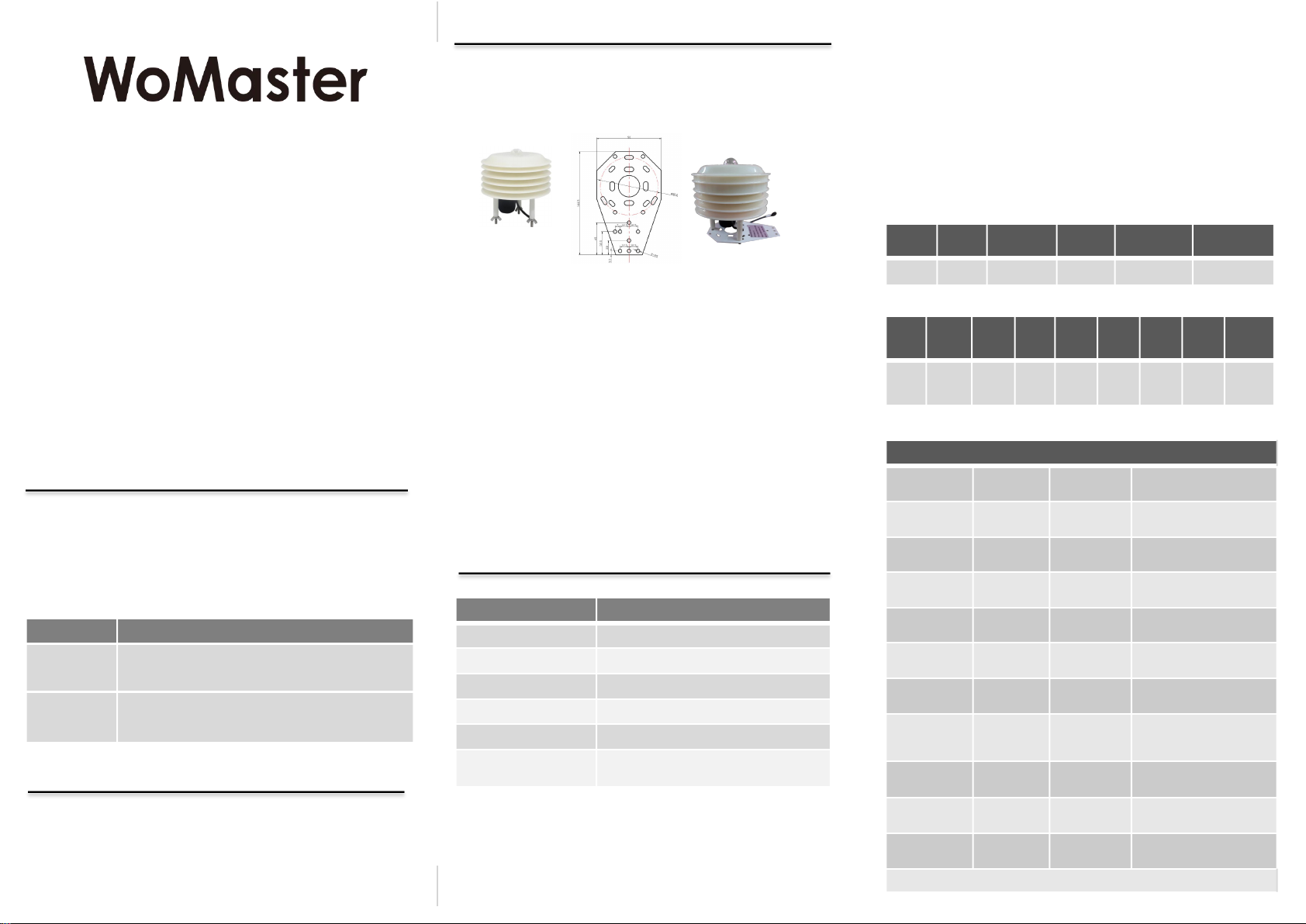
・Antenna
The device supports 1 antennas sockets. The product attaches a black
LoRa antenna.
This device supports WoMaster End-Node Utility management.
1. Connect the Micro USB interface on the device to the PC through
Micro USB cable
2. Open WoMaster End-Node Utility on PC.
3. Key in the username and password in login screen. The default user
name and password are admin
4. Utility automatically identifies the COM interface or select correct
COM manually,then clicks on “Connect” to c onnect to t he
device.When the utility is connected to the device,“Model Name” will
display device model name connected to Utility and “Connect” will
change to “Disconnect”。
uFor further feature configurations, please refer to User Manual.
uPlease download latest WoMaster Utility from the website:
www.womaster.eu.
・Management
At WoMaster, you can use the online service forms to request the
support. The submitted forms are stored in server for WoMaster team
member to assign tasks and monitor the status of your service. Please
feel free to write to help@womaster.eu if you encounter any problems.
・Support
WoMaster reserves the right to make changes to this QIG or to the
product hardware at any time without notice. It is the user’s responsibility
to determine whether there have been any such updates or amendments
herein.
Defects, malfunctions, or failures of the warranted Product(s) caused by
damage resulting from unforeseeable incidents (such as lightings, floods,
fire, etc.), environmental and atmospheric disturbances, other external
forces such as power line disturbances and surge, host computer
malfunction and virus, incorrect power input, or incorrect cabling, incorrect
grounding and damages caused by misuse, abuse and unauthorized
alteration or repair are not warranted.
・Disclaimer
・Warranty
5-year Global warranties are available for WoMaster products assuring
our customers that the products shall remain free from defects in
workmanship or materials and conform in all material respects to
WoMaster specifications, or Purchaser’s supplied and accepted
specifications. The warranty is limited to the repair and/or replacement, at
WoMaster' sole discretion, of the defective product during its warranty
period. The customer must obtain a Return Merchandise Authorization
(RMA) approval code prior to returning the defective Product to WoMaster
for service. The customer agrees to prepay shipping charges, to use the
original shipping container or equivalent, and to insure the Product or
assume the risk of loss or damage in transit. Repaired or replaced
products are warranted for ninety (90) days from the date of repair or
replacement, or for the remainder of the original product's warranty period,
whichever is longer.
This manual suits for next models
1
Popular Weather Station manuals by other brands

La Crosse Technology
La Crosse Technology Wireless Weather Station instruction manual

NexxTech
NexxTech Professional Weather Station user manual

Carrin
Carrin KW9005W-SM user manual

Holman
Holman Aspect WS5029 user guide

SwitchDoc Labs
SwitchDoc Labs WeatherSense Aftershock Assembly and Test Manual

SwitchDoc Labs
SwitchDoc Labs SkyWeather WXLink ASSEMBLY AND TESTING GUIDE

La Crosse Technology
La Crosse Technology 302-604B Faqs

Sencor
Sencor SWS 7300 instruction manual

La Crosse Technology
La Crosse Technology C80758-UK manual

IROX
IROX HBR555t user manual

La Crosse Technology
La Crosse Technology V21-WTH General information

York Survey Supply
York Survey Supply 33405 operating instructions