Woodcraft Mission Inspired 125405 User manual

22
22
211
11
10 W0 W
0 W0 W
0 Wood County Industrial Pood County Industrial P
ood County Industrial Pood County Industrial P
ood County Industrial Park, Park, P
ark, Park, P
ark, P.O. Box 1.O. Box 1
.O. Box 1.O. Box 1
.O. Box 1686, P686, P
686, P686, P
686, Parkersburg, WV 26arkersburg, WV 26
arkersburg, WV 26arkersburg, WV 26
arkersburg, WV 2611
11
102-102-1
02-102-1
02-1686686
686686
686 1
INSTRUCTION MANUAL
for
77B02
Mission Inspired Mantel Clock
#125405

22
22
211
11
10 W0 W
0 W0 W
0 Wood County Industrial Pood County Industrial P
ood County Industrial Pood County Industrial P
ood County Industrial Park, Park, P
ark, Park, P
ark, P.O. Box 1.O. Box 1
.O. Box 1.O. Box 1
.O. Box 1686, P686, P
686, P686, P
686, Parkersburg, WV 26arkersburg, WV 26
arkersburg, WV 26arkersburg, WV 26
arkersburg, WV 2611
11
102-102-1
02-102-1
02-1686686
686686
686 2
Before beginning the assembly of your Woodcraft precut clock kit, read these instructions and become familiar with the parts
list, drawings and photos which illustrate the text. We also recommend a dry assembly “practice run” on all parts prior to actual
gluing. Instructions or information in bold print are critical for proper assembly and for avoiding irreversible assemblyInstructions or information in bold print are critical for proper assembly and for avoiding irreversible assembly
Instructions or information in bold print are critical for proper assembly and for avoiding irreversible assemblyInstructions or information in bold print are critical for proper assembly and for avoiding irreversible assembly
Instructions or information in bold print are critical for proper assembly and for avoiding irreversible assembly
mistakes.mistakes.
mistakes.mistakes.
mistakes.
Important Notes About Solid Wood
One of the unique characteristics of solid hardwood is the varying hues and patterns within a single piece of lumber. Since no
two trees are identical, no two pieces of wood can be exactly alike either. Each has its own characteristics created by nature,
not by man. Unlike plastics and some veneers in which the grain pattern is symmetrical, solid hardwood has irregular and
asymmetrical graining, which adds to the overall beauty. In the same manner, the various shadings and colors within solid
hardwood are part of its beauty.
Drilling Holes
The wood components of this kit have screw clearance holes predrilled and countersunk. When assembling, it is necessaryWhen assembling, it is necessary
When assembling, it is necessaryWhen assembling, it is necessary
When assembling, it is necessary
to mark through these holes and to drill starter or “pilot” holes in the adjoining part. A ball point pen refill, an awl, or ato mark through these holes and to drill starter or “pilot” holes in the adjoining part. A ball point pen refill, an awl, or a
to mark through these holes and to drill starter or “pilot” holes in the adjoining part. A ball point pen refill, an awl, or a
sharpened nail make fine marking tools. Starter holes should be drilled approximatelysharpened nail make fine marking tools. Starter holes should be drilled approximately
sharpened nail make fine marking tools. Starter holes should be drilled approximately 11
11
1//
//
/
44
44
4" deep. If using a power drill," deep. If using a power drill,
" deep. If using a power drill," deep. If using a power drill,
" deep. If using a power drill,
be very careful not to drill through the adjoining wood part.be very careful not to drill through the adjoining wood part.
be very careful not to drill through the adjoining wood part.
Clamping
Clamping is necessary to insure tight accurate fits of glued joints. Conventional F-style or band clamps may be used. Large
rubber bands can often be used in place of conventional clamps.
Glue
We recommend Titebond yellow aliphatic resin glue used according to the manufacturer’s instructions. Use a glue brush or
cotton swab to spread the glue. A thin even spread on both parts is best. Clean up excess glue by scraping it off with a knife
blade or scraper. Do not wipe glue off with a damp cloth as the moisture of the cloth will thin the glue and allow it toDo not wipe glue off with a damp cloth as the moisture of the cloth will thin the glue and allow it to
Do not wipe glue off with a damp cloth as the moisture of the cloth will thin the glue and allow it toDo not wipe glue off with a damp cloth as the moisture of the cloth will thin the glue and allow it to
Do not wipe glue off with a damp cloth as the moisture of the cloth will thin the glue and allow it to
soak deeply into the wood. This will show in the final finish of your clock.soak deeply into the wood. This will show in the final finish of your clock.
soak deeply into the wood. This will show in the final finish of your clock.
Definitions
Before You Begin
Notes
Tools
•F-style clamps/band clamp/rubber bands
•yellow woodworking glue
•screwdriver
•pencil
•awl
•drill
•drill bits: 1/8", 5/64", 7/64"

22
22
211
11
10 W0 W
0 W0 W
0 Wood County Industrial Pood County Industrial P
ood County Industrial Pood County Industrial P
ood County Industrial Park, Park, P
ark, Park, P
ark, P.O. Box 1.O. Box 1
.O. Box 1.O. Box 1
.O. Box 1686, P686, P
686, P686, P
686, Parkersburg, WV 26arkersburg, WV 26
arkersburg, WV 26arkersburg, WV 26
arkersburg, WV 2611
11
102-102-1
02-102-1
02-1686686
686686
686 3
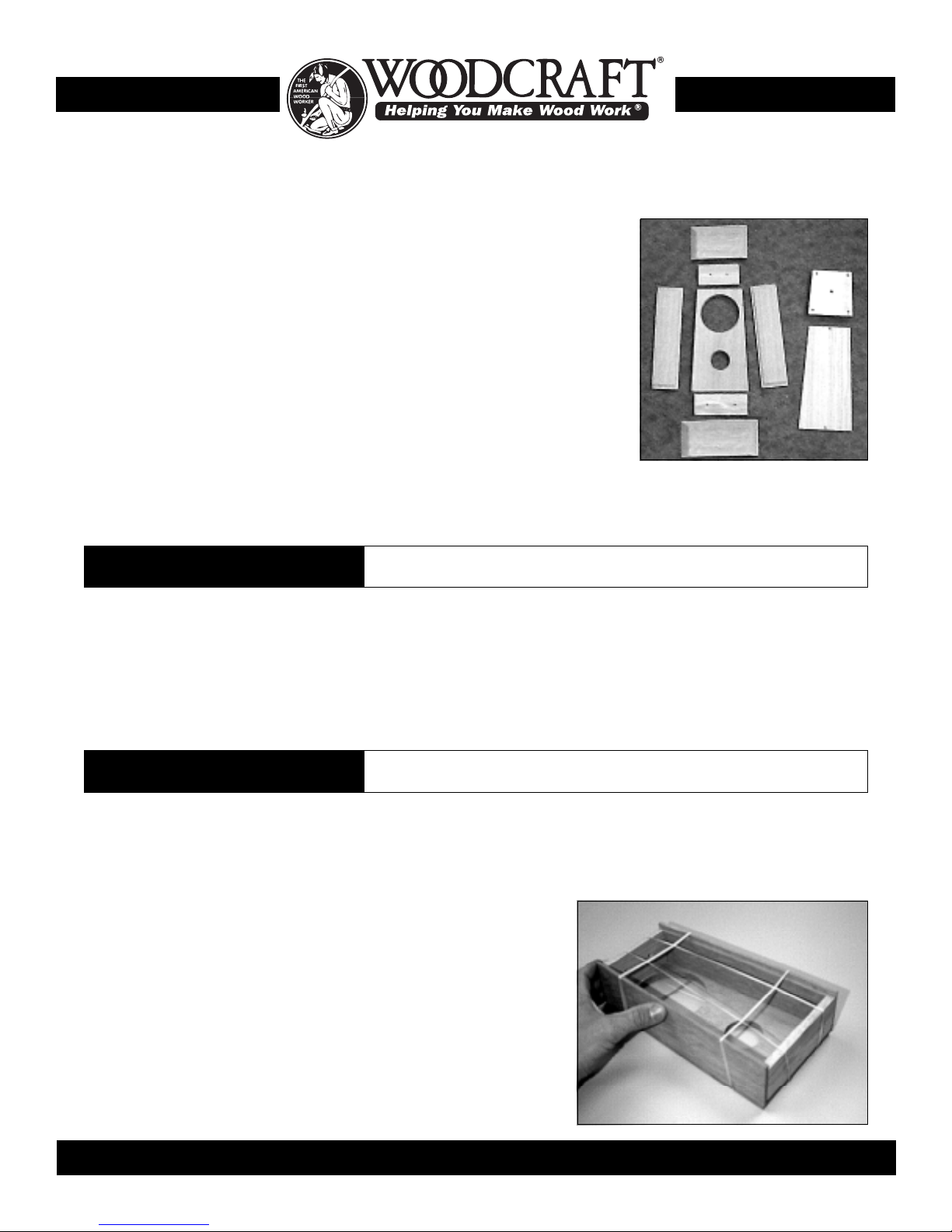
Mission Mantle Clock Kit Parts List
Part #Part #
Part #Part #
Part # QtyQty
QtyQty
Qty DescriptionDescription
DescriptionDescription
Description Dimensions, T” x W” x L”Dimensions, T” x W” x L”
Dimensions, T” x W” x L”Dimensions, T” x W” x L”
Dimensions, T” x W” x L”
Wood Components:Wood Components:
Wood Components:
1 ............ (1) ......... Clock base ................ 1/2" x 63/4" x 33/8"
2 ............ (1) ......... Clock top ................... 1/2" x 53/4" x 33/8"
3 ............ (1) ......... Clock front ................ 1/2" x 43/8" (top)/57/
16" (bottom) x 10"
4 ............ (2) ......... Side panels............... 5/16" x 21/2" x 10"
5 ............ (1) ......... Interior base ............. 3/8" x 2" x 51/
16"
6 ............ (1) ......... Interior top ............... 3/8" x 2" x 315/16"
7 ............ (1) ......... Plywood case back .. 3/16" x 4" (top)/51/
16" (bottom) x 931/32"
8 ............ (1) ......... Dialboard .................. 3/
4" x 33/
4" (top)/43/16" (bottom) x 45/16"
Hardware:Hardware:
Hardware:Hardware:
Hardware:
(4) ......... #8 x 1" Brass Flat Head Wood Screws
(4) ......... #6 x 5/8" Brass Flat Head Wood Screws
(2) ......... #4 x 5/8" Brass Flat Head Wood Screws
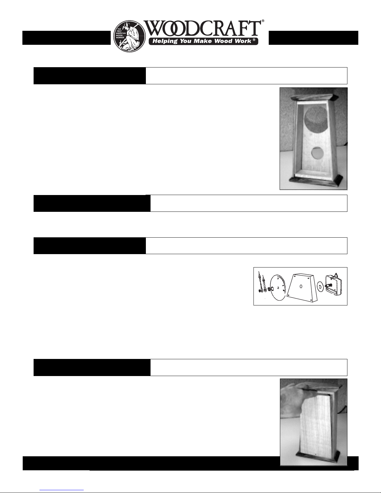
Quartz Movement/Accessories:Quartz Movement/Accessories:
Quartz Movement/Accessories:
(1) ......... Quartz movement w/mounting hardware
(1) ......... Mission Style hands set
(1) ......... 37/8" Mission Style dial
(1) ......... “AA” battery
11
11
1
33
33
3
44
44
444
44
4
55
55
5
66
66
6
22
22
2
88
88
8
77
77
7
Most of the flat surfaces of the Mission Mantle Clock have been factory sanded, but final finish sanding may be required
according to personal preferences. If additional sanding is required, sand all parts prior to assembly.If additional sanding is required, sand all parts prior to assembly.
If additional sanding is required, sand all parts prior to assembly.If additional sanding is required, sand all parts prior to assembly.
If additional sanding is required, sand all parts prior to assembly.
Sanding should be accomplished in a series of steps. Begin with a medium grit (120 or 150) paper and remove any scratches
or blemishes. Final sanding should be accomplished with a 180 grit paper, removing the scratches left by previous coarser
paper. We do not recommend that you sand oak with anything finer that 180 grit paper as the wood will not be veryWe do not recommend that you sand oak with anything finer that 180 grit paper as the wood will not be very
We do not recommend that you sand oak with anything finer that 180 grit paper as the wood will not be veryWe do not recommend that you sand oak with anything finer that 180 grit paper as the wood will not be very
We do not recommend that you sand oak with anything finer that 180 grit paper as the wood will not be very
receptive to stain.receptive to stain.
receptive to stain.
Take care not to deform the crisp lines of the bevels if sanding is performed on the clock top.Take care not to deform the crisp lines of the bevels if sanding is performed on the clock top.
Take care not to deform the crisp lines of the bevels if sanding is performed on the clock top.
Case Assembly
2
1.1.
1.1.
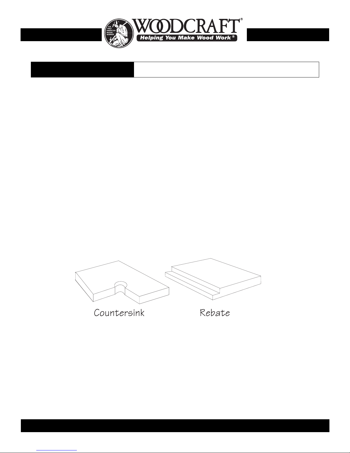
1. In a dry run, position the clock front (#3), face down on a flat horizontal surface. Place the non rebate edge of the side
panels (#4) into the rebate on the clock front. The smooth, non rebate side of the side panel should be on the outside of the
clock. Slip the top (#6) and bottom (#5) interiors between the side panels so that the countersink borings are on the inside of
the clock case..
2.2.
2.2.
2. Practice clamping or “rubber banding” the components together, ensuring that all pieces are flush on the top and bottom of
the case. When comfortable with the dry run procedure, glue the case
assembly together in the order described below.
3.3.
3.3.
3. Spread glue onto both the horizontal and vertical surfaces of the 1/
4"
rebate on the clock front. Spread a thin film of glue on the “mating” surfaces
of the side panels.
4.4.
4.4.
4. Place the non rebate edge of each side panel into the rebate of the clock
front.
5.5.
5.5.
5. Spread glue on both ends of the top and bottom interior pieces. PositionPosition
PositionPosition
Position
the top and bottom interior pieces into place between the side panels sothe top and bottom interior pieces into place between the side panels so
the top and bottom interior pieces into place between the side panels so
that the countersink borings are on the inside of the clock case.that the countersink borings are on the inside of the clock case.
that the countersink borings are on the inside of the clock case.
6.6.
6.6.
6. Using lightweight “F” style clamps or rubber bands, clamp the assembly
until dry. Ensure that the side panels and top/bottom interior pieces areEnsure that the side panels and top/bottom interior pieces are
Ensure that the side panels and top/bottom interior pieces areEnsure that the side panels and top/bottom interior pieces are
Ensure that the side panels and top/bottom interior pieces are
flush with the top and bottom edge of the clock front. Failure to achieveflush with the top and bottom edge of the clock front. Failure to achieve
flush with the top and bottom edge of the clock front. Failure to achieve
a flush fit will result in an ill fitting base and top.a flush fit will result in an ill fitting base and top.
a flush fit will result in an ill fitting base and top.
1Surface Preparation

22
22
211
11
10 W0 W
0 W0 W
0 Wood County Industrial Pood County Industrial P
ood County Industrial Pood County Industrial P
ood County Industrial Park, Park, P
ark, Park, P
ark, P.O. Box 1.O. Box 1
.O. Box 1.O. Box 1
.O. Box 1686, P686, P
686, P686, P
686, Parkersburg, WV 26arkersburg, WV 26
arkersburg, WV 26arkersburg, WV 26
arkersburg, WV 2611
11
102-102-1
02-102-1
02-1686686
686686
686 4
Top & Base Assembly
3
Finishing
4
Mounting The Dial & Movement
5
1.1.
1.1.
1. Position the plywood dial board (#8) into the clock so that the top edge of the dial board is tight against the interior top.
Mark the location of the predrilled holes on the back of the clock front.
2.2.
2.2.
2. Using a sharp scratch awl, put a 1/4" deep starter hole at each location. You can drillYou can drill
You can drillYou can drill
You can drill
a starter hole with ana starter hole with an
a starter hole with an 77
77
7//
//
/6464
6464
64" bit, but take great care not to drill through the clock" bit, but take great care not to drill through the clock
" bit, but take great care not to drill through the clock" bit, but take great care not to drill through the clock
" bit, but take great care not to drill through the clock
front.front.
front.front.
front.
3.3.
3.3.
3. Mount quartz movement and dial to the dial board as shown in the diagram (right). It
is not necessary to glue the dial face to the dial board. The shaft nut of the quartz
movement and pressure of the dial board against the back of the clock front will hold
the dial in position.
4.4.
4.4.
4. Position the dial board/dial/movement assembly into position and screw in place with (4) #6 x 1" brass wood screws.
5.5.
5.5.
5. If the dial is not aligned properly loosen the dial board wood screws and the movement shaft nut and reposition the dial.
When the dial alignment is correct, tighten the wood screws and shaft nut.
6.6.
6.6.
6. Cut pendulum shaft to length. Proper length shaft will result in pendulum bob centered in smaller circular opening on the
clock front. Install “AA” battery.
Case Back Installation
6
1.1.
1.1.
1. Insert the plywood case back into rear of case and check for fit. It should not fit too tightly.
Mark starter hole locations in the interior top and base.
2.2.
2.2.
2. Remove the plywood case back and drill 5/64" starter holes 1/4" deep as marked.
3.3.
3.3.
3. Install case back using (2) #4 x 5/8" brass flat head wood screws.
DO NOT GLUE THE CASE BACK IN PLACE!DO NOT GLUE THE CASE BACK IN PLACE!
DO NOT GLUE THE CASE BACK IN PLACE!
1.1.
1.1.
1. Position the glued case assembly onto the clock base (#1) so that the case is centered side to
side on the base. All of the edges on the base have been slightly “relieved” with the exception of
the back edges. Ensure that the non-relieved, square, back edges are oriented toward the back
of the clock and flush with the rear edge of the side panels.
2.2.
2.2.
2. With the case in position, carefully mark the position of the predrilled holes on the interior
base. Using a 7/64" bit drill a 1/
4" deep starter hole for each predrilled hole.
3.3.
3.3.
3. Spread a thin film of glue on the base of the case, place the case on the base and screw in
position with 2 #6 x 5/8" brass, flat head wood screws.
4.4.
4.4.
4. Position the bevel edge top (#2) on the case so that the non beveled, square edge is oriented
to the rear of the clock and flush with the rear edge of the side panels.
5.5.
5.5.
5. With the top in position, carefully mark the position of the predrilled holes of the interior top.
Using a 7/64" bit drill a 1/4" deep starter hole for each predrilled hole.
6.6.
6.6.
6. Spread a thin film of glue on the top of the case, place the top on the case and screw in
position with 2 #6 x 5/8" brass, flat head wood screws.
The Mission Mantle Clock may be left natural or stained according to your preference. For our catalog photograph, we utilized a
golden oak Gel Finish (Woodcraft stock # 34M13). When staining the wood, we recommend you experiment with scrap or the
inside of the case until you are sure of the results. All visible areas should be finished, the dial board may be left unfinished.
Table of contents
Popular Clock manuals by other brands

Control Company
Control Company TRACEABLE 1076 operating instructions

Atlas
Atlas 830 Series Installation

La Crosse Technology
La Crosse Technology WS-8011UM-TWC instruction manual

Oregon Scientific
Oregon Scientific CP100 quick start guide

Oregon Scientific
Oregon Scientific RM928N user manual

La Crosse Technology
La Crosse Technology WT-3129BX1 Faqs