Wooden Gear Clocks UK Clockerel Manual

Wooden Gear Clocks UK
316 Pickering Road, Hull, East Yorkshire, UK Tel 01482 509277
http://wooden-gear-clocks.co.uk/
Build Manual for “Clockerel” Electromechanical Wooden Geared Clock
Thank you for purchasing the “Clockerel” electromechanical clock kit from Wooden Gear Clocks UK. We called it
the “Clockerel” as it resembles a flightless bird of some kind, probably, but not exclusively, a Clockerel.
The aim of this manual is to make the construction of this kit enjoyable, safe and rewarding. The clock is
powered by 4 x D cell Alkaline batteries.
SAFETY
Always read and digest any safety instructions that came with your tools. Wooden Gear Clocks do not accept
any responsibility for any injuries incurred during the construction of this clock.
TOOLS
The tools required to carry out this build are as follows:
A bench vice (fitted with jaw protectors) is desirable but not essential.
An electric drill, preferably battery operated.
2mm,3mm and 4mm drill bits
A half round file approximately 25mm flat.
Soldering iron, solder etc.
Rapid setting epoxy resin e.g. Araldite
PVA wood glue
Shellac, color up to the customer.
Foam sanding block
Plastic “Scotchbrite” washingup pad. 1-2 required.
Aluminium oxide or silicon carbide abrasive paper. Grade 80, 120 and 180.

Wooden Gear Clocks UK
316 Pickering Road, Hull, East Yorkshire, UK Tel 01482 509277
http://wooden-gear-clocks.co.uk/
Aerosol can of automotive clear spray lacquer (Acrylic).
Jig as drawing Clockerel-0016
Flat 300mm steel rule
Sharp knife/scalpel
SKILLS
A knowledge of basic wood finishing techniques and the ability to read drawings. Basic soldering skills are also
required, but not essential as you could always get someone with the skills to perform these tasks. Six soldered
joints are required to complete the clock.
These instructions are to be read in conjunction with drawings Clockerel-0001 to 0017.
PARTS
Please check all parts against the parts list (BOM). If any parts are missing then please contact us immediately.
Disregard any dimensions given verbally in the build video as designs change. Use drawings only.
The assembly order in the video may not be as these instructions.
INSTRUCTIONS
1. Drawing Clockerel-0001/0002
Trial fit the frame into the base. If it is too tight to push in easily by hand then remove a small amount of
MDF from the frame until a smooth push fit is achieved. This is best done with the file or a sharp edged
knife.
Apply PVA adhesive to one of the mating surfaces of the base and press together with the other part .
Place the base on a flat surface with a heavy object to sandwich the assembly. Alternatively use clamps
with protection to prevent damage to the surfaces.
Ensure that the two parts are correctly aligned around the edges and that adhesive has squeezed out all
round. This ensures that there are no dry voids around the edge which would show up during finshing.
Leave for 4 hours and then finish as per preparation of the MDF parts.
2. Preparation of parts
MDF parts:
It is very important that the edges of these parts are well sanded to a smooth finish. The finish of the
edges will reflect in the overall appearance of the clock. All machining marks and adhesive MUST be
removed with 80 grade abrasive paper or the edge of the file as shown in my video. Only sand/file in the
direction of the edge, NOT across it. Sanding across the edge could break away the veneer as well as
not giving a good finish. Work your way down to the 180 grade paper and finish with a fine foam sanding
pad or Scotchbrite. The edges should now be smooth with an even texture. The veneered side can be
sanded with just the 180 grade abrasive paper and Pad/Scotchbrite, working in the direction of the grain.
Only a light sanding is required.
After preparation apply shellac to all exterior surfaces and sand with a Pad/Scotchbrite when dry, paying
particular attention to the edges. Repeat this process until the edges are smooth with an even dark
texture (approximately 4/5 times).
The MDF parts can now be finished with clear acrylic applied in several light coats with sanding in
between.
Plywood parts:
The faces should be carefully sanded with 180 grade abrasive paper wrapped around a sanding block.
Lay the parts on a flat surface and carefully sand the faces in the direction of the grain. The faces can
also be sanded by gluing a sheet of 180 grade to a flat surface and rubbing the parts on this.
Wrap a small amount of 180 grade paper into the size of a flattened cigarette to do the inner edges and
teeth. Only sand the teeth to remove ragged edges. DO NOT sand too much as the profile of the teeth
may be effected. The faces of the parts may be treated with shellac as above if required.

Wooden Gear Clocks UK
316 Pickering Road, Hull, East Yorkshire, UK Tel 01482 509277
http://wooden-gear-clocks.co.uk/
The spacers can be inserted onto to the 3mm mandrill supplied and sanded using a battery drill and
abrasive paper. The spacers should be trial fitted to the shafts. They should be tight but not so tight that
they cannot be moved with finger pressure. If they are too tight then enlarge the hole with the 3mm drill.
Twist the spacers onto the drill in a counter clockwise direction so that the faces are not split. If you drill
into the in a conventional direction the faces will be damaged. You can now enlarge the hole by holding
the spacer and sliding the drill bit up and down.
Brass shafts:
The shafts should be cut to the required length (5 in all). I am unable to get brass rod that fits with the
required tolerances to the bearings. The shafts should be a smooth sliding fit in the bearings. This
makes subsequent assembly much easier and prevents damage to the parts.
Put a shaft into the battery drill and sand with 120 grade abrasive for about 5 seconds, moving the
abrasive up and down the shaft. Finish with 180 grade and trial fit to the bearing. Repeat until the
required fit is achieved. Repeat for the other end.
3. Drawing Clockerel-0002
When the desired finish has been achieved the bearings can be fitted into the holes as shown in section
C-C. The bearings should be pressed partly into the holes using finger pressure. If they are too tight then
lightly sand the inside of the holes until the desired fit is achieved. Push the bearings fully home with the
flat side of a 25mm wide steel rule or similar. This ensures that the bearings are square and flush with
the face of the frame.
Stick the pads to the base (ensure it’s the right side) and temporarily attach the base cover to the base
with the 4 screws provided. Carry out instruction 4 before gluing the frame to the base.
Ensure that the hole for the frame is clear and temporarily fit the frame to the base. The hole in the base
is 6mm longer than the adjoining piece of the frame. Therefore the frame requires fitting central in the
hole. Check that the pendulum bearing is approximately 139mm from the base when measured at 90
degrees from the base.
When happy a small amount of epoxy can be put around the hole and the parts fixed permanently.
4. Clockerel-0003/0004
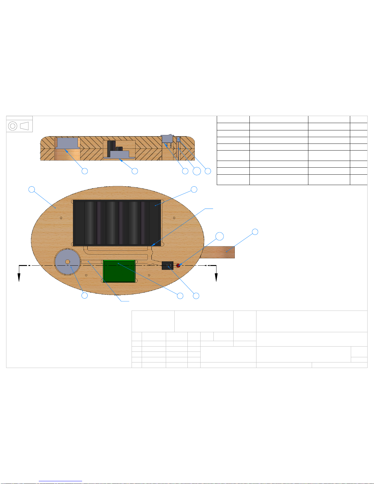
The electrical components should now be installed. Remove the base cover and place the base inverted
onto the work surface. Cover the work surface with a towel or similar to protect the base finish and
switch after installation
Cut 1 piece of red wire 165mm long and 1 piece 250mm long. Solder these to the switch terminals and
install into the frame with the wires passing through the hole.
Cut 1 piece of black wire 125mm long and solder this to the negative terminal of the battery box. Ensure
that the wire orientation is such that the wire will be pointing the correct direction when the battery box is
installed.
Cut 1 piece of red wire 100mm long and 1 piece of black wire 100mm long. Solder the red wire to the
longer terminal of the LED and the black wire to the shorter terminal. Push a piece of the heat shrink
material over one of the terminals to prevent a short circuit between the terminals. Shrink this on with a
cigarette lighter, being careful not to burn it.
Insert the switch into the base. Solder the longer wire to the battery box positive terminal ensuring the
correct orientation.
The battery box can now be fitted.
Insert the LED into the hole in the base. This hole may require cleaning as glue can enter it during the
base assembly. Place the LED to the depth you prefer.
Place the coil into the frame recess paying attention to the orientation shown in drawing Clockerel-0004.
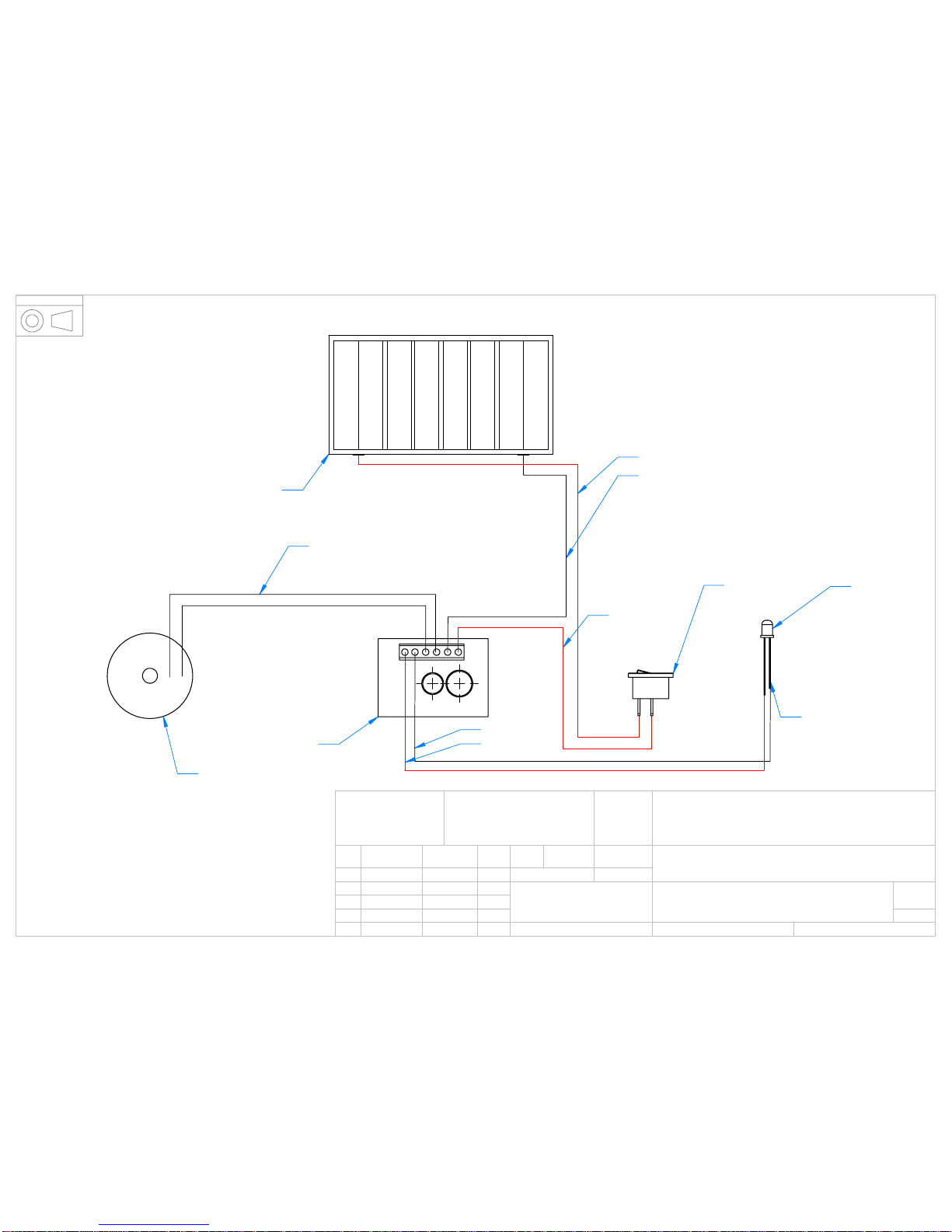
Burn or sand the lacquer from the coil terminals and connect these to the 2 center terminals of the circuit
board. Connect the LED wires as shown in the wiring schematic. Connect the black wire from the battery
box and the red wire from the switch to the circuit board as shown. Be careful to get these the correct
way round. The circuit board is not polarity protected due to resistance issues. Incorrect connection
would damage the board.

Wooden Gear Clocks UK
316 Pickering Road, Hull, East Yorkshire, UK Tel 01482 509277
http://wooden-gear-clocks.co.uk/
Insert the circuit board into the base as shown. Cut a piece of foam to the correct length to keep the coil
in place. Masking tape may be used to keep the wires in the wiring grooves during installation.
Reassemble the cover to the base.
5. Clockerel-0009 / 30 tooth wheel assembly
Inset the shaft 1 through the 3mm hole in the jig allowing 6mm to protrude (use wheel to measure this).
Place a small amount of epoxy inside the hole of part 2 and not on the shaft. This ensures that oozing
adhesive does not cause the part to stick to the jig. Place the wheel over the shaft ensuring that the best
side faces towards the front of the clock. Remove the part from the jig by pushing on the rod from
beneath and not by pulling the wheel. Remove it when the remaining mixed adhesive has dried.
Now place a small amount of adhesive on the shaft adjacent to and on part 2. Slide part 3 down the
shaft and into position. Allow to dry. This method of assembly ensures that adhesive does not get on the
shaft.
When the assembly is fully dried, slide part 3 down the shaft. Place a small amount of epoxy onto the
mating face of part 4 being careful not to get any into the hole. Push part 4 fully onto the shaft and slide
part 3 back up to adhere to it. Leave until remaining epoxy mix has almost dried and then carefully
withdraw from the shaft without misaligning the parts. Allow it to dry thoroughly. Remove any epoxy from
the end of the shaft which may have leaked out.
The part can now be fitted to the clock temporarily with the 2 washers (5). The part should have
approximately 1mm of end float (side to side movement) when assembled in the frame. File the end of
the shaft until the desired end float is achieved. Ensure that part 4 is fitted fully onto the shaft. The part
should spin freely.
6. Clockerel-0008 / 60 tooth wheel assembly
Repeat the basic assembly instructions as above for the 30 tooth wheel assembly.
7. Clockerel-0011 / 64 tooth wheel assembly
Repeat the instructions as above for the 30 tooth wheel assembly and the 60 tooth wheel assembly.
This assembly cannot be adjusted for end float until the final assembly.
8. Clockerel-0006 / Ratchet wheel assembly
Place the shaft into the jig with approximately 15mm of shaft protruding. Place a small amount of epoxy
into the hole of the ratchet wheel (part 1) with a cocktail stick or similar. Slide the ratchet wheel onto the
shaft making sure it is fitted the correct way round. It should feel rough when you rotate your finger
around the edge in a clockwise direction. Place a small amount of epoxy onto the spacer (part 3) and
slide into position whilst holding the shaft. Place a small amount of epoxy onto the 8 tooth wheel (part 2)
and slide into position. Ensure that part 2 is fully fitted by pushing the shaft upwards whilst pushing part
2 downwards. Leave it to dry.
Remove from the jig as previously described and place a small amount of epoxy onto the mating face of
part 4. Push part 3 into position until full home.
The part can now be fitted to the clock temporarily with the 2 washers (5) and part 6. The part should
have approximately 1mm of end float (side to side movement) when assembled. File the end of the shaft
until the desired end float is achieved. Ensure that part 6 is fitted fully onto the shaft. The part should
spin freely.
9. Clockerel-0005 / Pendulum pawl assembly
Insert the pawl pin (part 10) into the assembly jig with just over 6mm protruding. Place a small amount of
epoxy resin into the smaller hole in the drive pawl lever (part 3). Push this over the pin paying attention
to the orientation. Leave the part to dry and remove from the jig.
Place a small amount of epoxy resin inside the largest hole of the Non return pawl (part 5). The amount
of resin should just be enough to wet the surface and no more. Excess could be squeezed onto the

Wooden Gear Clocks UK
316 Pickering Road, Hull, East Yorkshire, UK Tel 01482 509277
http://wooden-gear-clocks.co.uk/
bearing seal. Push the bearing into the hole making sure it is square to the face. To ensure it is square
after insertion, lay the part onto a flat surface and push the bearing down onto the same surface.
Glue the blind spacer (part 2) onto the end of the pendulum shaft (part 1). When this has dried the part 2
can be sanded by placing the shaft into the drill. Check that no adhesive remains on the face or shaft.
Remove if necessary.
Place a small amount of adhesive onto part 2 and the adjacent 3mm of shaft. Slide the drive pawl lever
onto the shaft and into position. Leave it to dry.
Place the drive pawl (part 4) over the pin in part 3. Check that it is free to rotate on the shaft. If not then
open the hole carefully with a 2mm drill. Again insert in a counter clockwise direction.
When free to rotate, assemble onto the shaft with the retainer (part 11). Some end float is required for
free movement.
Place a washer over the shaft 1 followed by part 5 as shown. A further 4 washers are placed along the
shaft followed by part 6. Part 5 should pivot freely at this point as the washers should ensure clearance
between it and the adjacent parts. If it does not pivot freely check the bearing 8 for freedom of rotation.
The part can now be fitted to the frame with the 2 washers (9) and the part 7. Check for 1mm end float
and adjust shaft length as necessary.
10. Clockerel-0010 / Hour hand assembly
Cut part 1 to length. Make this part 48mm long. Clean the inside of the tube where it has been cut to
remove any rough edges.
Insert the tube into the assembly jig allowing approximately 12.5mm to protrude. Place a small amount
of epoxy resin inside the hole in the 32 tooth wheel (part 4). Slide the wheel (part 4) over the tube until
flush with the jig ensuring the best side faces the front of the clock. Approximately 6.5mm of tube should
now be protruding from the gear wheel 4. Some epoxy will run inside the tube but this can be removed
with a 3mm drill when dry. Allow the part to dry and remove from the jig.
Check that the 4mm spacers (part 3) fit onto the tube. If they are too tight then open the hole slightly with
a 4mm drill until a sliding fit on the tube.
Place a small amount of epoxy onto the 32 tooth wheel where the adjoining spacer will touch and push
the spacer onto the tube. Repeat for the other 3 spacers and allow it to dry.
The spacers can now be sanded smooth by inserting the assembly on to the mandrill and into the
battery drill. Do not tighten the mandrill too much as this can distort the tube.
Glue the hour hand (part 2) onto the tube orientating it in a non random position. Follow this by the last
spacer.
Set the assembly aside.
11. Clockerel-0007 / Pendulum shaft assembly
Cut part 1 to 220mm from the 1/8” wooden dowel. Cut part 2 to 30mm from the 4mm OD tube and part 3
to 45mm from the M3 brass rod.
Mark 15mm along the wooden dowel and reduce the diameter of this section until it fits tightly into part 2.
Glue these two parts together paying particular attention to the alignment. When dry glue part 3 into part
2, again paying attention to alignment. Glue the magnet (part 6) onto the Rivet nut (part 4). Set the
assemblies aside to dry.
When dry, screw part 4 onto part 3 approximately 3 turns. Adjust the length of the wooden shaft so that
the magnet just clears the base when the shaft is pushed into the pendulum mount.
12. Clockerel-0013 / Face assembly
Cut the 9mm dowel into 2 lengths each 58mm long (2). Sand each end until it is a sliding fit into the
frame and the face. Glue the dowels into the face as shown.
Set the assembly aside.
13. Clockerel-0014 / Clockerel assembly exploded.
Table of contents
Popular Clock manuals by other brands

Sapling
Sapling NTP 7000 Series installation manual

Amano
Amano MTX-30F Installation & operation guide

La Crosse Technology
La Crosse Technology BBB86118v3 Setup guide

BEARWARE
BEARWARE 304474 manual

LS & S
LS & S RTC103U instruction manual

BitGen Technologies
BitGen Technologies LED Walk/Don't Walk Clock user manual

Heathkit
Heathkit GC-1005 Assembly manual

Oregon Scientific
Oregon Scientific PRYSMA RMR221P manual

Andrew O'Malley
Andrew O'Malley DOTKLOK Assembly instructions

Nixie Clock
Nixie Clock Divergence Meter user manual

La Crosse Technology
La Crosse Technology WS-8256-AL user manual

Mini Gadgets
Mini Gadgets MCPro user manual