6 SAFETY Alitec Pavement Saw (Rev. 3/2/2007)
(Safety Rules continued from previous page)
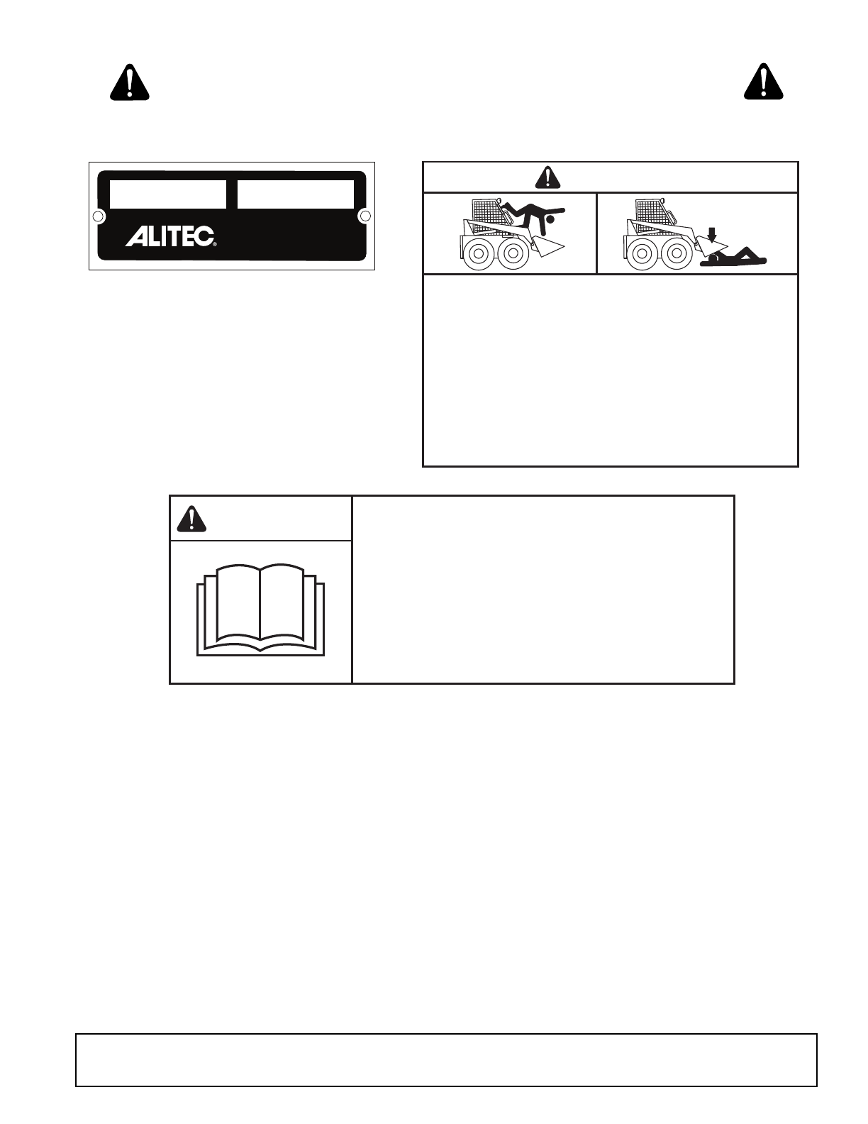
Power unit must be equipped with ROPS and
seat belt/operator restraint. Keep seat belt/operator
restraint securely fastened/engaged. Falling off
power unit can result in death from being run over
or crushed. Keep ROPS systems in place at all
times.
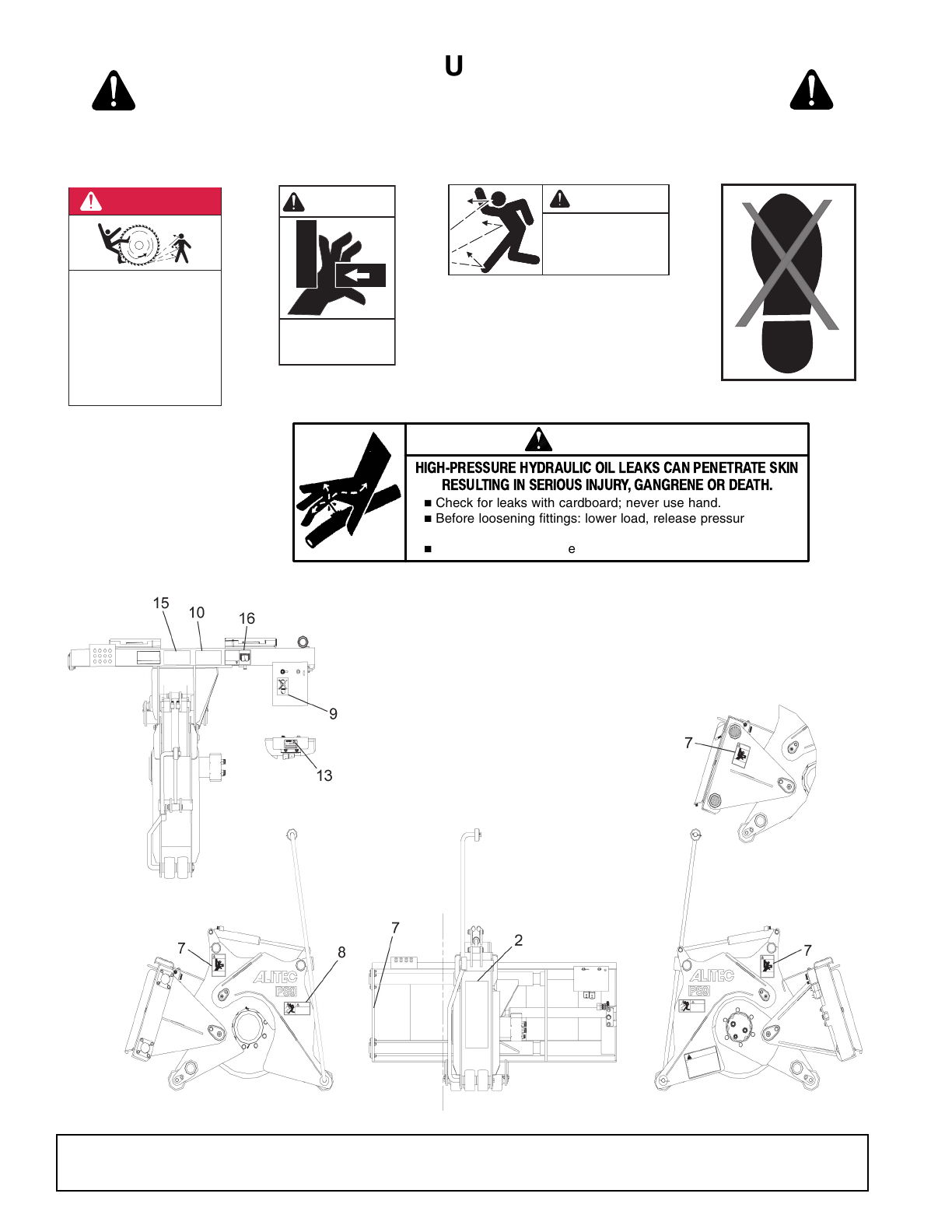
Make sure all safety decals are installed.
Replace if damaged. (See Safety Decals section for
location.)
Make sure shields and guards are properly
installed and in good condition. Replace if damaged.
Inspect and clear area of stones, branches, or
other hard objects that might be thrown, causing
injury or damage.
OPERATION
Improper operation can cause the machine to
tip or roll over and cause injury or death.
• Keep power unit lift arms and attachment as
low as possible.
• Do not travel or turn with power unit lift arms
and attachment raised.
• Turn only on level ground.
• Go up and down slopes, not across them.
• Keep the heavy end of the machine uphill.
• Do not overload the machine.
Never use attachment to carry loads that exceed
the rated operating capacity or other specifications
of the power unit. Check your power unit manual or
see your dealer for rated operating capacity.
Exceeding this capacity can cause machine to tip,
roll over, or present other hazards that can cause
injury or death.
Do not allow bystanders within 25 feet of the
area when operating, attaching, removing, assem-
bling, maintaining, or servicing equipment.
Consult local utilities before digging. Know
location and depth of all underground cables, pipe-
lines, and other hazards in working area and avoid
contact.
Contact with high voltage, overhead power
lines, underground cables, gas lines, and other
hazards can cause serious injury or death from
electrocution, explosion, or fire.
Keep bystanders away from equipment.
Do not operate or transport equipment while
under the influence of alcohol or drugs.
Operate only in daylight or good artificial light.
Keep hands, feet, hair, and clothing away from
equipment while engine is running. Stay clear of all
moving parts.
Always comply with all state and local lighting
and marking requirements.
Do not allow riders. Do not lift or carry anybody
on the power unit or attachments.
Always sit in power unit seat when operating
controls or starting engine. Securely fasten seat
belt/operator restraint, place transmission in park
or neutral, engage brake and ensure all other con-
trols are disengaged before starting power unit
engine.
Look down and to the rear and make sure area
is clear before traveling in reverse.
Use extreme care when working close to fences,
ditches, other obstructions, or on hillsides.
Do not operate or transport on steep slopes.
Do not stop, start, or change directions sud-
denly on slopes.
Use extreme care and reduce ground speed on
slopes and rough terrain.
Watch for hidden hazards on the terrain during
operation.
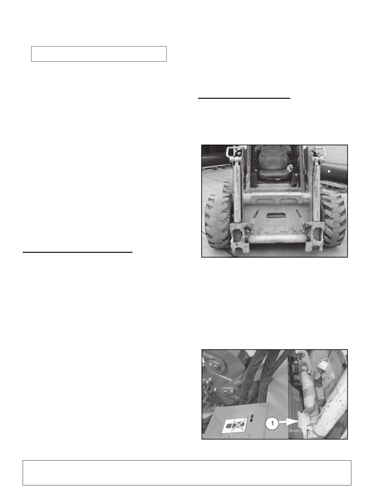
NEVER GO UNDERNEATH EQUIPMENT. Never
place any part of the body underneath equipment
or between moveable parts even when the engine
has been turned off. Hydraulic system leak-down,
hydraulic system failures, mechanical failures, or
movement of control levers can cause equipment
to drop or rotate unexpectedly and cause severe
injury or death.
• Service work does not require going under-
neath implement.
• Read Operator's Manual for service instruc-
tions or have service performed by a qualified
dealer.
Before making any adjustments on attachment,
stop engine and engage parking brake. Never
adjust or work on attachment while the power unit
or attachment is running.
Before leaving operator's seat, lower lift arms
and put attachment on the ground. Engage brake,
stop engine, remove key, and remove seat belt.
MAINTENANCE
Before leaving operator's seat, lower lift arms
and put attachment on the ground. Engage brake,
stop engine, remove key, and remove seat belt.
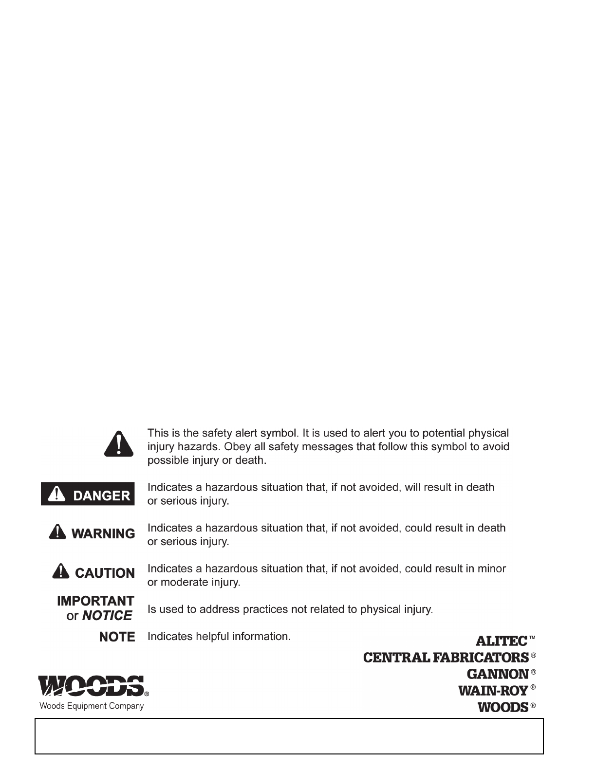
SAFETY RULES
ATTENTION! BECOME ALERT! YOUR SAFETY IS INVOLVED!