14 15
3730 E. SOUTHERN AVE., PHOENIX, AZ 85040 | USA 800.778.8779 | WORKHORSEPRODUCTS.COM
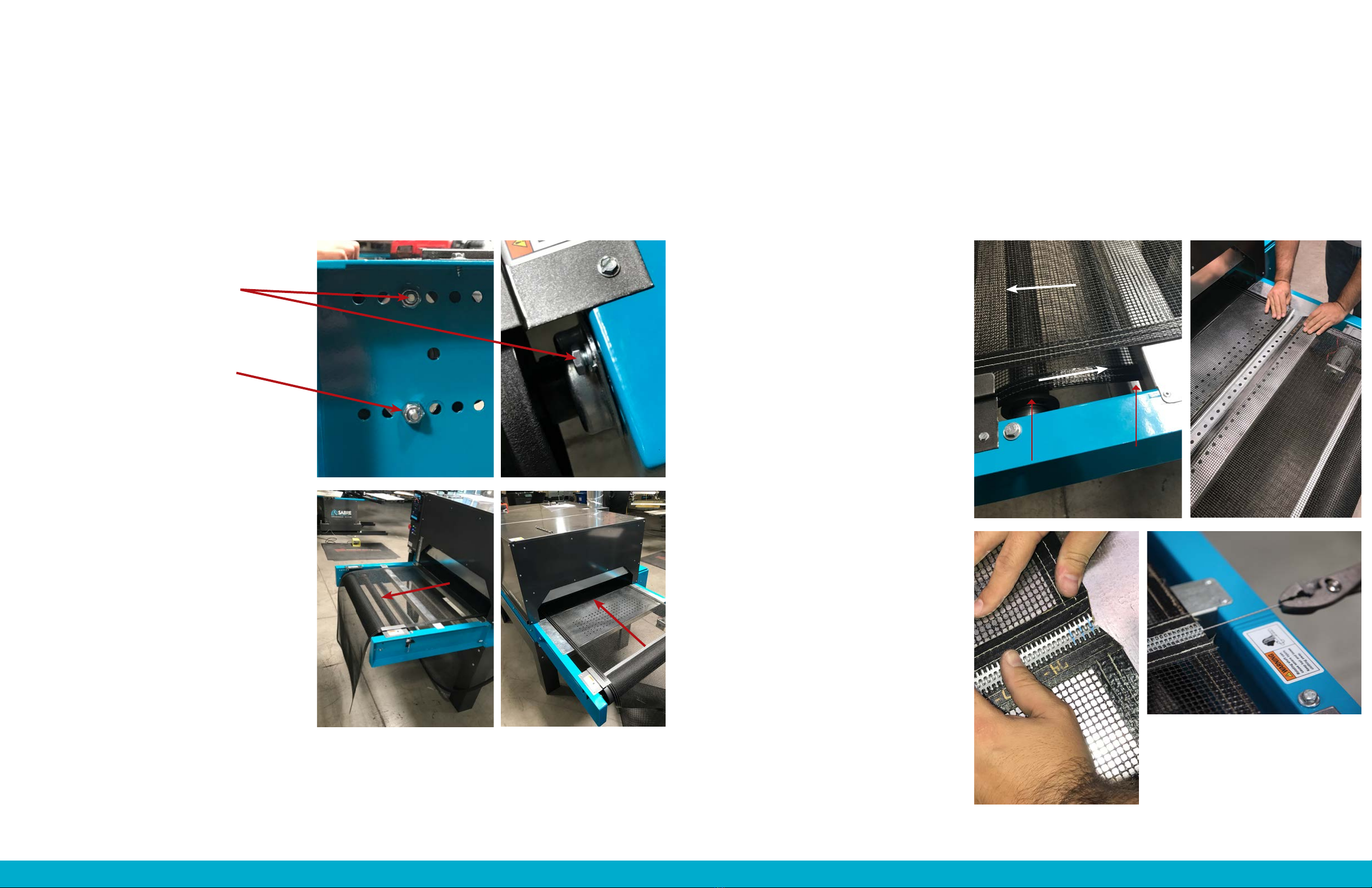
ASSEMBLY
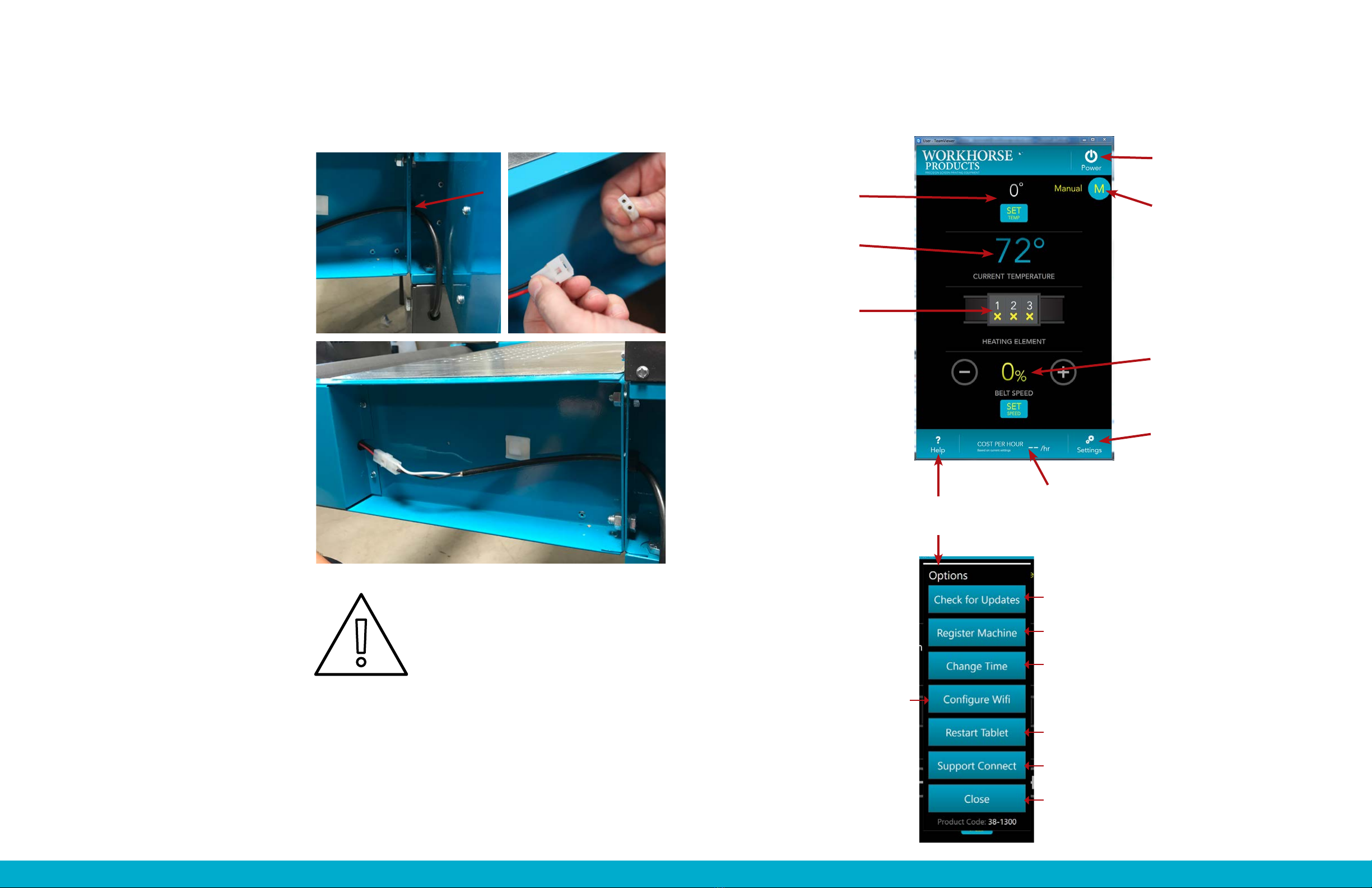
STEP 5: CONNECTING THE BELT DRIVE MOTOR
On the outfeed side, take the
belt drive motor cable and feed it
through the hole located at the edge
of the arm.
Connect the belt drive motor cable
to the motor cable.
Congratulations!
The Powerhouse Series II Dryer is
now fully assembled!
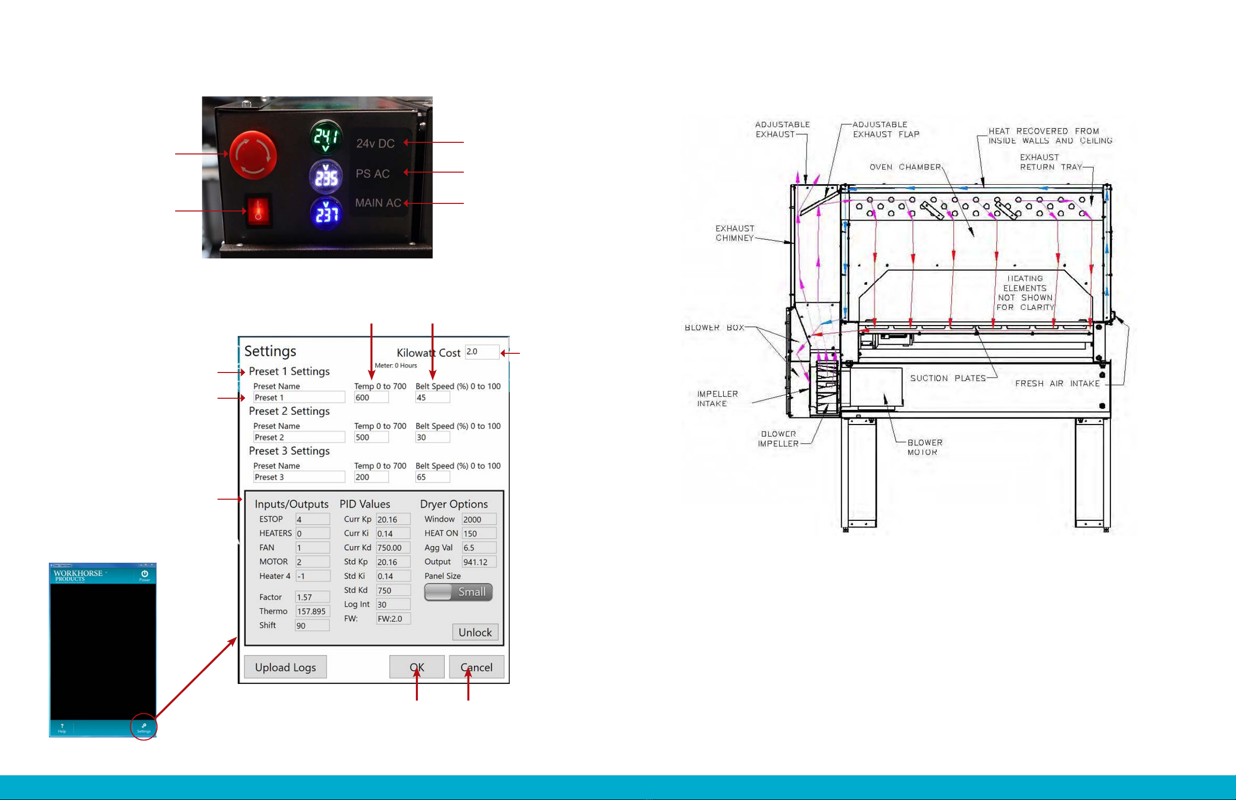
The size and specifications of the electrical connections made during installation MUST BE
DETERMINED BY A LICENSED ELECTRICIAN. FOLLOW ALL LOCAL BUILDING AND PLANNING
CODES. Failure to do so may result in damage to the unit, building, or cause serious injury.
Before any electrical connections are made verify all safety precautions have been taken to ensure
the safety of all shop personnel. The dedicated breaker providing power to the dryer MUST BE
OFF, AND USE OF A SERVICE LOCKOUT TAG IS REQUIRED. This will prevent anyone from turning
on the power as the connections are being made. After all safety precautions have been taken
the electrical connections can be made. All electrical connections must be made by a licensed
electrician. Refer to factory specifications for proper installation.
1.
2.
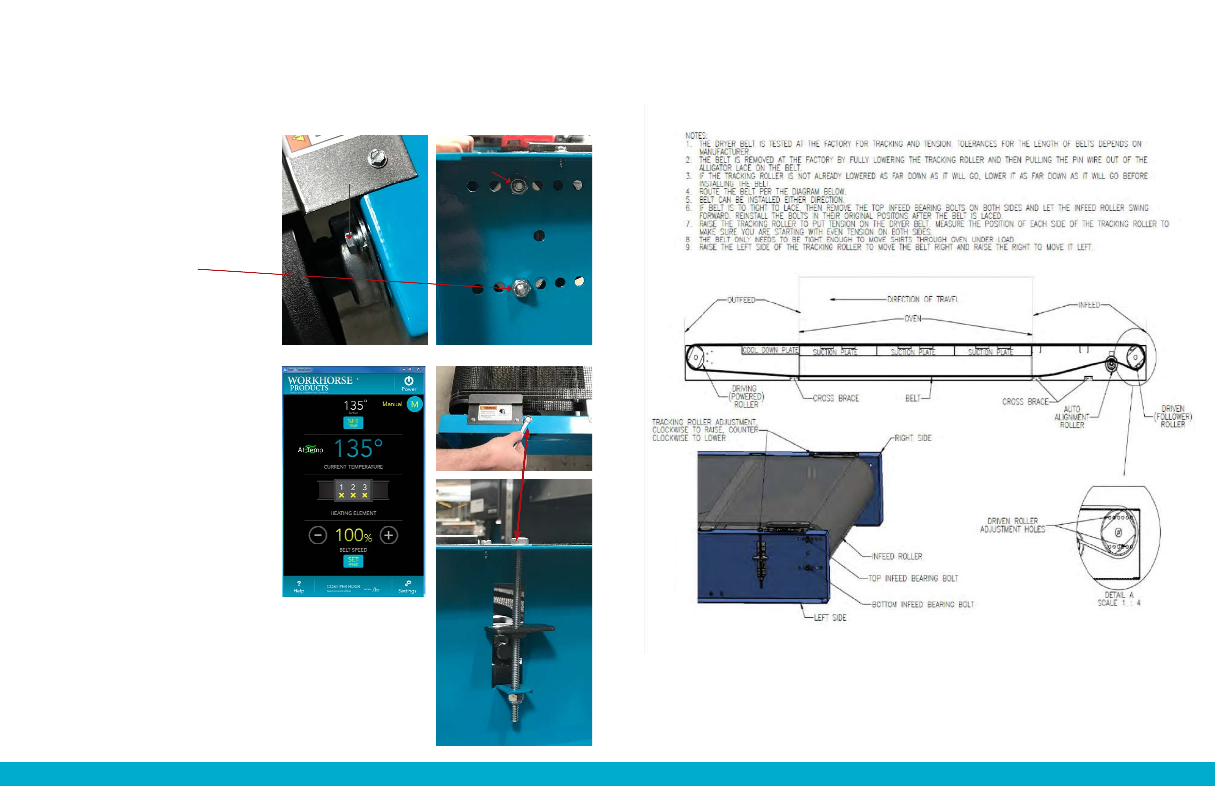
CONTROLS
SET TEMPERATURE
The temperature the
dryer is set to achieve CURRENT MODE
The mode the dryer is on.
For example, if set to a preset,
the preset’s name would be the
current mode. Manual mode
means that the dryer is set to
manual settings without a preset.
BELT SPEED
The speed of the belt
Before turning the dryer on make sure that the belt is empty.
Touch the idle screen so it opens up into the main menu (shown below)
OPERATING COSTS
Based on temperature, airflow, and
exhaust settings the dryer is able to
calculate price per hour for every job.
CURRENT TEMPERATURE
The temperature the dryer
is currently at
HEATING ELEMENTS
Indicates the status of the
heating element. Whether
the heating element is
receiving power or when it
is actually on.
POWER
Turn the dryer on/off
SETTINGS
Opens the Settings
Menu (see pg. 16)
HELP
Opens the
Options Menu
CHECK FOR UPDATES
Checks for system updates (Wi-Fi Connection required).
REGISTER MACHINE
Registering the machine to the portal will allow you to update
the dryer and store machine logs in the service portal
CHANGE TIME
Adjusts the date and time on the machine.
CONFIGURE WI-FI
Opens the Wi-Fi configuration menu
where the machine can connect to Wi-Fi.
When connected to the Wi-Fi the
machine can receive updates,
communicate with the cloud, and allow
for remote troubleshooting.
RESTART TABLET
This will turn the tablet all the way off and reboot back to
the home screen. This may need to be done on occasion.
SUPPORT CONNECT
This will allow a Workhorse Tech to log in to your tablet to
see log files and/or other issues you may be having.
CLOSE
Will close the sub-menu and return to the Main Menu.