WPG STT1 User manual

KEEP FOR FUTURE REFERENCE
INSTRUCTIONS
International Version
MODEL NUMBER: STT1
SERIAL NUMBER: ___________
(please see serial label and record number here)
STOWAWAY TILT TABLE
READ ALL INSTRUCTIONS AND WARNINGS
BEFORE USING THIS TABLE
DESIGNED FOR THE MATERIALS HANDLING PROFESSIONAL
P.O. Box 368 –908 West Main
Laurel, MT USA 59044
phone 800-548-7341
phone 406-628-8231
fax 406-628-8354


Rev 9.0/1-18 1 STT1: #35151
TABLE OF CONTENTS
TABLE OF CONTENTS ...................................................................................................... 1
SPECIFICATIONS............................................................................................................ 2
WARNINGS ..................................................................................................................... 2
ASSEMBLY....................................................................................................................... 3
USAGE FEATURES ........................................................................................................... 9
USAGE ........................................................................................................................... 10
BEFORE USING THE TABLE ............................................................................................... 10
Taking Safety Precautions ..........................................................................................................................10
Evaluating the Intended Use.......................................................................................................................10
TO FOLD UP OR UNFOLD THE TABLE ................................................................................... 10
TO LOAD THE TABLE........................................................................................................ 11
TO TILT THE LOAD .......................................................................................................... 11
TO TRANSPORT THE LOAD ON THE TABLE ............................................................................ 12
TO UNLOAD THE TABLE.................................................................................................... 12
AFTER USING THE TABLE ................................................................................................. 12
MAINTENANCE.............................................................................................................. 13
INSPECTION SCHEDULE ................................................................................................... 13
Every-Use Inspection .................................................................................................................................13
Frequent Inspection ...................................................................................................................................13
Periodic Inspection ....................................................................................................................................13
Infrequent Use ..........................................................................................................................................13
TESTING SCHEDULE ........................................................................................................ 13
MAINTENANCE SCHEDULE ................................................................................................ 13
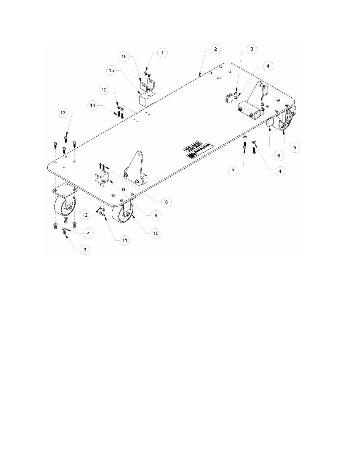
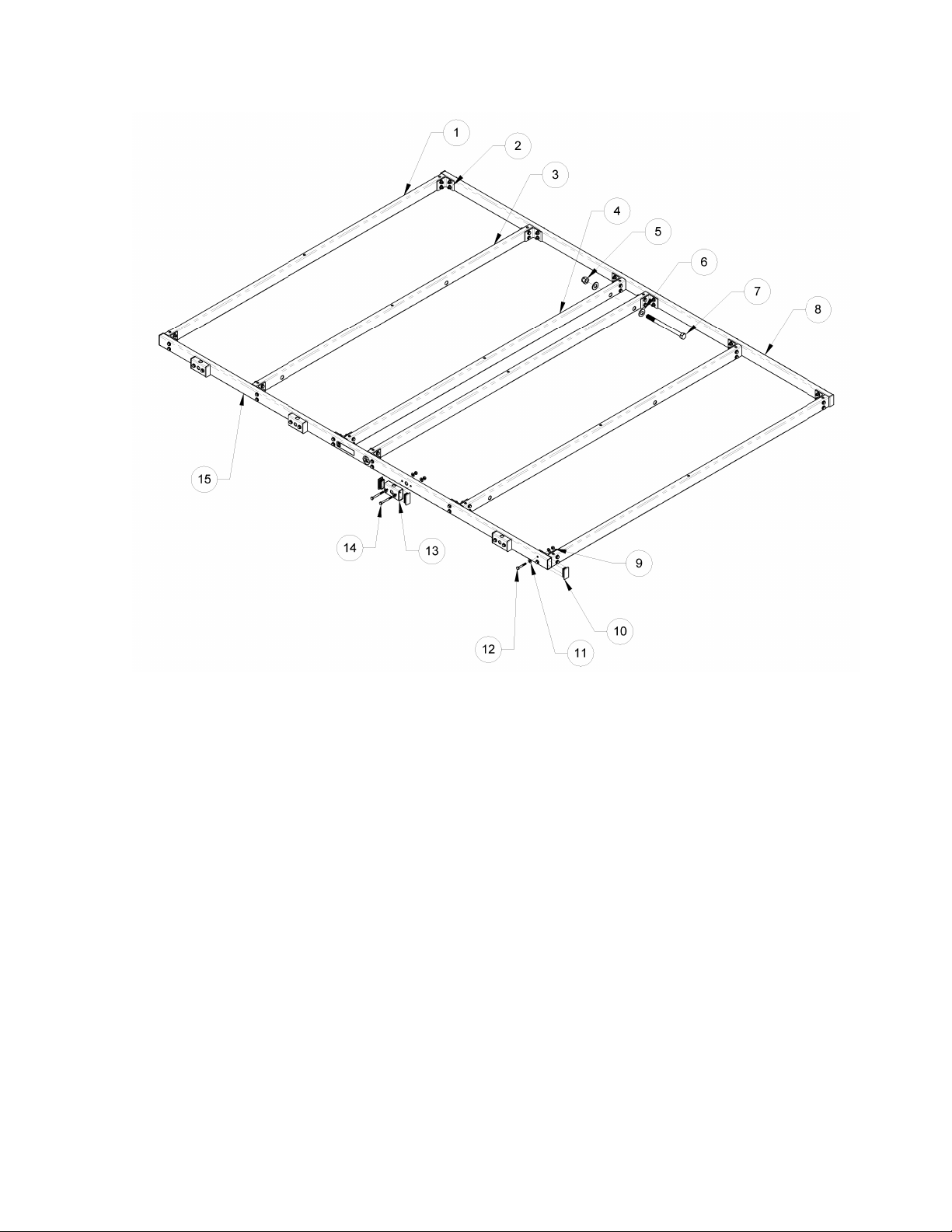
REPLACEMENT PARTS LIST .......................................................................................... 14
LIMITED WARRANTY.................................................................................................... 15

Rev 9.0/1-18 2 STT1: #35151
SPECIFICATIONS
Model Number:
STT1 (includes STT base kit and STTTF table top surface)
Maximum Load Capacity:
500 lbs [225 kg]
Load Characteristics:
Flat sheet material
Maximum thickness = 2" [5 cm]
Load Tilting Capability:
Manual, 80° flat/upright load orientation
Dimensions:
Table top = 69¼" x 96" [1759 mm x 2438 mm]
Table height = 35½" [902 mm]
Folded width = 27" [686 mm] with load support rollers
Folded height = 83" [2108 mm]
Weight:
414 lbs [188 kg] (334 lbs [152 kg] without table top surface)
WARNINGS
Powr-Grip is pleased to offer the most reliable materials handling products
available. Despite the high degree of security provided by this tilt table, certain
precautions must be observed to protect the user and others.
Always
wear personal protective equipment that is appropriate for the material being handled.
Follow trade association guidelines.
Never
use a table that is damaged, malfunctioning, or missing parts.
Never
remove or obscure warning labels.
Never
use a table if the load capacity or any warning appears to be missing or obscured.
Never
exceed the load capacity or attempt to handle loads the table was not designed for (see
SPECIFICATIONS).
Never
attempt to handle cracked or broken glass with this table.
Always
position yourself and others to avoid injury in the event that the load shifts unexpectedly
while using the table.
Never
allow people to ride or stand on the table or the load being handled.
Never
leave tilted loads unattended.
Always
remember that modifications to the table may compromise its safety. Woods Powr-Grip
cannot be responsible for the safety of a table that has been modified by the customer. For
consultation, contact Wood's Powr-Grip.

Rev 9.0/1-18 3 STT1: #35151
ASSEMBLY
1) Remove all packing materials for restraining or protecting the table during shipping, and
remove the table's pieces from the shipping container.
2) Assemble the left and right assemblies for the large pivots as shown in Figure 1.
1) LARGE PIVOTS
3) 3/8" SAE FLAT WASHERS
5) 3/8-16 X 3" HEX HEAD BOLTS −
GRADE 5
2) 3/8-16 NYLON LOCK NUTS −GRADE 8
4) LARGE PIVOT BASES
FIGURE 1: LARGE PIVOT ASSEMBLIES

Rev 9.0/1-18 4 STT1: #35151
3) Assemble the base assembly as shown in Figure 2.
1) 5/16-18 X 5/8" FLAT HEAD SOCKET BOLT −140 KSI
9) CENTER PIVOT
2) BASE PLATE W/LABELS
10) 5" DIA X 2" FIXED CASTER −900 LBS CAPACITY
3) 3/8-16 NYLON LOCK NUT −GRADE 8
11) 5/16-8 NYLON LOCK NUT −GRADE 8
4) 3/8" SAE FLAT WASHER
12) 5/16" SAE FLAT WASHER
5) 5" DIA X 2" SWIVEL CASTER W/LOCK −800 LBS CAPACITY
13) 3/8-16 X 1-1/8" HEX HEAD BOLT −GRADE 5
6) END PLUG FOR 2" X 2" X 3/16" TUBING
14) 5/16-18 X 1" HEX HEAD BOLT −GRADE 5
7) 3/8-16 X 1-1/4" HEX HEAD BOLT −GRADE 5
15) CENTER PIVOT SPACER
8) 5/16-8 X 1-1/4" FLAT HEAD SOCKET BOLT
16) SIDE PIVOT
FIGURE 2: BASE ASSEMBLY

Rev 9.0/1-18 5 STT1: #35151
FIGURE 3: SUPPORT LEG ASSEMBLY
4) Assemble the support leg assembly as shown in Figure 3. Do not over-tighten moving parts:
They should move with enough resistance to maintain position unless movement is
intentionally initiated.
1) 1/4-20 X 1/2" HEX HEAD BOLT −GRADE 5
16) SHORT VERTICAL TUBE OF SUPPORT LEG ASSEMBLY
2) 1/4" SAE FLAT WASHER
17) TUBE END FOR 2" X 2" X 11-12 GAGE TUBING −3/8-16 TAP
3) SUPPORT LEG STOP
18) 3/8-16 X 2-7/8" SWIVEL LEVELING FOOT
4) 3/8-16 NYLON LOCK HEX NUT −GRADE 8
19) 5/16-18 X 2-3/4" HEX HEAD BOLT −GRADE 5
5) 3/8" SAE FLAT WASHER
20) END PLUG FOR 2" X 2" X 0.120" TUBING
6) NYLON SPACER
21) PIVOT
7) SUPPORT LEG LATCH
22) 5/16-18 X 3" FLAT HEAD SOCKET BOLT
8) 5/8-11 NYLON LOCK HEX NUT −GRADE 8
23) 5/16-18 X 3" HEX HEAD BOLT −GRADE 5
9) SHORT LINKAGE TUBE
24) 5/16-18 X 2-3/4" HEX HEAD BOLT −GRADE 5
10) 3/8-16 X 1-1/4" HEX HEAD BOLT −GRADE 5
25) TILT LATCH HANDLE
11) 3/8" NYLON FLAT WASHER
26) 5/8" SAE FLAT WASHER
12) LONG VERTICAL TUBE OF SUPPORT LEG ASSEMBLY
27) 5/8-11 X 5-1/2" HEX HEAD BOLT −GRADE 5
13) HORIZONTAL TUBE OF SUPPORT LEG ASSEMBLY
28) 5/16" X 1" X 1/4-20 SOCKET HEAD SHOULDER BOLT − 140 KSI
14) 5/16" SAE FLAT WASHER
29) 5/16" X 3/8" X 1/4-20 SOCKET HEAD SHOULDER BOLT − 140 KSI
15) 5/16-18 NYLON LOCK HEX NUT −GRADE 8
30) TILT LATCH SPRING

Rev 9.0/1-18 6 STT1: #35151
FIGURE 4: BASE FRAME ASSEMBLY
5) Assemble the base frame assembly as shown in Figure 4.
1) LONG LINKAGE TUBES
8) 5/8" SAE FLAT WASHER
2) SHORT LINKAGE TUBE
9) NYLON SPACER
3) BASE ASSEMBLY
10) 5/8" SAE FLAT WASHER
4) 5/8-11 NYLON LOCK HEX NUT −GRADE 8
11) 5/8-11 X 3-1/4" HEX HEAD BOLT −GRADE 5
5) 5/8" SAE FLAT WASHER
12) 5/8-11 X 4" HEX HEAD BOLT −GRADE 5
6) 5/8-11 X 4" HEX HEAD BOLT −GRADE 5
13) 5/8-11 X 8" HEX HEAD BOLT −GRADE 5
7) 5/8-11 NYLON LOCK HEX NUT −GRADE 8
14) SUPPORT LEG ASSEMBLY

Rev 9.0/1-18 7 STT1: #35151
FIGURE 5: TOP FRAME ASSEMBLY
6) Assemble the top frame assembly as shown in Figure 5.
1) VERTICAL TUBE C
9) 1/4-20 NYLON LOCK HEX NUT −GRADE 8
2) CORNER BRACKET
10) END PLUG FOR 1" X 2" X 10-14 GAGE TUBING
3) VERTICAL TUBE B W/SERIAL LABEL
11) 1/4" SAE FLAT WASHER
4) VERTICAL TUBE A
12) 1/4-20 X 1-3/4" HEX HEAD BOLT −120 KSI
5) 5/8-11 NYLON LOCK HEX NUT −GRADE 8
13) TABLE TOP ROLLER SPACER
6) 5/8" SAE FLAT WASHER
14) 1/4-20 X 2-1/2" HEX HEAD BOLT −GRADE 5
7) 5/8-11 X 8" HEX HEAD BOLT −GRADE 5
15) BOTTOM TABLE TUBE W/LABELS
8) TOP TABLE TUBE W/LABELS

Rev 9.0/1-18 8 STT1: #35151
FIGURE 6: FINAL ASSEMBLY
7) Assembly the final assembly as shown in Figure 6:
8) Securely attach the table top surface to the top frame assembly, using the hardware supplied.
Note: When the base kit (STT) is purchased separately, install an appropriate table top
surface. This typically consists of plywood sheets cut to fit the frame dimensions, and it may
include a felt covering, to help prevent scratching of the load material. A top surface of this
type (STTTF) or a felt kit to construct such a surface using customer-supplied wood (STTTFK)
may be purchased from Wood's Powr-Grip or a distributor (see REPLACEMENT PARTS LIST).
9) Test the table as directed in MAINTENANCE: TESTING SCHEDULE.
1) 5/8-11 NYLON LOCK HEX NUT −GRADE 8
5) TOP ASSEMBLY
2) 5/8" SAE FLAT WASHERS
6) BASE FRAME ASSEMBLY
3) NYLON SPACER
7) ROLLER ASSEMBLY
4) 5/8-11 X 4" HEX HEAD BOLT −GRADE 5

Rev 9.0/1-18 9 STT1: #35151
USAGE FEATURES
Note: Components featured in the following instructions for using or maintaining
the table are underlined on their first appearance in each section.
Standard STT1 shown.
1) LOAD SUPPORT ROLLER
3) TILT LATCH HANDLE
6) CASTER BRAKE
2) TABLE TOP
4) SUPPORT LEG
7) BASE
5) VERTICAL STABILIZER ARM
Figure A

Rev 9.0/1-18 10 STT1: #35151
Figure B
USAGE
BEFORE USING THE TABLE
Perform all inspections and tests required by the INSPECTION and TESTING SCHEDULES (see
MAINTENANCE). In addition, the following preparations must be completed prior to handling any
load.
Taking Safety Precautions
The operator must be trained in all relevant industry and regulatory standards for the operation of
the table in its geographical location (eg, OSHA standards in the USA).
The user must read and understand this
INSTRUCTIONS
manual, including all
WARNINGS
,
before using the table. If necessary, contact Wood’s Powr-Grip or an authorized dealer for
assistance.
WARNING: Always wear appropriate personal protective equipment.
The user must wear any personal protective equipment and take any other precautions required
to handle the load safely. Consult appropriate trade association guidelines to determine what
precautions are necessary for each type of load material.
Evaluating the Intended Use
The user must determine whether the table is capable of performing each
intended task, in view of specific design limitations: Consult the
SPECIFICATIONS to review the Maximum Load Capacity and Load Tilting
Capability, as well as the Load Characteristics required to use the table.
Any other use is not recommended.
Using the table in wet environments may require the user to take special
precautions: Although the table's exterior surfaces can tolerate some
exposure to water vapor, submerging the table or using it in rain may
damage its components; these and similar conditions must be avoided.
TO FOLD UP OR UNFOLD THE TABLE
Before folding a table (see Figure B), apply the caster brakes and remove
any load, making sure to use correct lifting technique. If the load support
rollers are installed, you may reorient them, in order to achieve a narrower
folded table width. Tilt the table top to its upright position (see TO TILT THE
LOAD to follow) and lift the support leg upward, making sure to use correct
lifting technique. Then pull the vertical stabilizer arm back until it
straightens out. Rotate the latch plate to secure the arm in place. To
unfold the table, reverse this procedure. To move a folded table, release the
caster brakes and roll the table to the desired location; then reapply the caster
brakes.

Rev 9.0/1-18 11 STT1: #35151
TO LOAD THE TABLE
Before loading a table in the horizontal position (see Figure A), lock the caster brakes and verify
that the tilt latch is securely engaged. Slide or carefully rest the load on the table, making sure to
use correct lifting technique. Dropping or bouncing a load onto the table may damage the frame.
Also make sure that the load is directly supported underneath by at least two structural members
of the table top frame. Uneven loading could also damage the table's frame.
When the load support rollers are installed, the table can be loaded in either the upright position
(see Figure C) or the folded position (see Figure B). Install the support rollers in their extended
position and secure them with the pins supplied. Lock the caster brakes, and set or roll an upright
load onto the support rollers, making sure to use correct lifting technique. The load surface
should rest against the table top surface. Be sure to use at least 2 support rollers at all times to
support the load. Loading the support rollers evenly provides stable support and makes tilting or
moving the table easier and more secure.
WARNING: If table is in folded position, make sure load will tip table over.
A table in the folded position (see Figure B) may lack sufficient counter-balance for the load and,
if so, could tip over. Support the load manually until you can verify that the table will not tip over
while supporting or transporting the load.
TO TILT THE LOAD
Tilting the load requires the load support rollers to
be installed on the table. Remember that the
loaded table requires more vertical space when
tilted from the horizontal position (see Figure A) to
the upright position (see Figure C).
Make sure
that the caster brakes are applied, that the load
support rollers are secured in their extended
position and that the load fits snugly against them,
since they will support the load weight in the
upright position.
WARNING: Short loads tend to pull table
abruptly upright; keep
load under control at all
times.
Use caution when releasing the tilt latch:
The
shorter and denser the load is, the more likely it is
to swing upward abruptly as soon as the latch is released. Release the table top to tilt upward by
pulling outward on the tilt latch handle. At the same time, maintain a hold on the table top to
keep the load under control throughout the tilt.
Failure to do so could result in serious
injury to the user or others.
Allow the table top to move upward until it attains the fully
upright position. If necessary, lift and/or push on the table top, making sure to use correct lifting
technique.
The table top should automatically remain in the upright position until the user initiates downward
movement. When tilting the loaded table back to the horizontal position (see Figure A), carefully
pull the table top down until it latches on the table base.
Figure C

Rev 9.0/1-18 12 STT1: #35151
TO TRANSPORT THE LOAD ON THE TABLE
Apply the caster brakes and load the table in the folded position (see Figure B), as directed in TO
LOAD THE TABLE preceding. Secure the load onto the table using a strap or other appropriate
means.
WARNING: Make sure load will not cause table to tip over.
A folded table may lack sufficient counter-balance for the load and, if so, could tip over. Support
the load manually until you can verify that the table will not tip over while supporting or
transporting the load. If necessary, place appropriate weight on the table base to stabilize the
loaded table. Release the caster brakes and use 2 people to roll the loaded table to the desired
location; then reapply the caster brakes.
CAUTION: Make sure floor is clean and free from obstructions.
The table casters are designed to be used only on smooth, even surfaces, so make sure to keep
the floor where the table is used clean and free from obstructions.
TO UNLOAD THE TABLE
Before unloading a table, apply the caster brakes. If the table is in the horizontal position, make
sure that the tilt latch is fully engaged. Then remove the load carefully from the table, making
sure to use correct lifting technique.
AFTER USING THE TABLE
Store the table in the folded position (see Figure B), in a dry location.

Rev 9.0/1-18 13 STT1: #35151
MAINTENANCE
INSPECTION SCHEDULE
Perform inspections routinely, according to the following frequency schedule:
Every-Use Inspection
• Check the table top surface for anything that may damage the load.
Frequent Inspection
(
following every 20-40 hours’ use; or whenever table is out of service for 1 month or more
)
• Examine the table’s structure for visual damage.
If any deficiency is detected during the inspection, correct it before using the table and perform
the Periodic Inspection to follow.
Periodic Inspection
(
following every 250-500 hours’ use; or whenever table is out of service for 1 year or more
)
• Examine the entire table for external evidence of looseness, excessive wear, deformation,
cracks, excessive corrosion, dents to structural or functional components, cuts, or any
deficiency which might constitute a hazard.
• Keep a written record of all Periodic Inspections.
If any deficiency is detected during the inspection, consult Wood’s Powr-Grip or an authorized
dealer for repair recommendations (see LIMITED WARRANTY).
Infrequent Use
If a table is used less than 1 day in a 4-week period, perform the Periodic Inspection
each time
before using the table
.
TESTING SCHEDULE
Perform these tests when placing the table in service
initially
and
each time following a repair or
modification
. Correct any deficiency and retest before using the table.
• Test all features and functions of the table (see USAGE FEATURES and USAGE).
MAINTENANCE SCHEDULE
Maintenance must be performed whenever a deficiency is indicated by routine inspections or
tests. Any maintenance warranted must be performed before resuming normal use of the table.

Rev 9.0/1-18 14 STT1: #35151
REPLACEMENT PARTS LIST
Stock No.
Description
Qty.
66483AM
Fixed Caster ‒5" Diameter x 2" Wide ‒Polyurethane on Iron
2
66483
Swivel Caster ‒5" Diameter x 2" Wide ‒Polyurethane on Iron ‒with Brake
2
59348AP
Load Support Roller
4
59334
Nylon Spacer
19
59344
Tilt Latch Spring
1
59321
Table Top Felt Kit (STTFK)
1
59320
Table Top Surface w/Felt Covering (STTTF)
1
49120
Tube End ‒2" x 2" x 11-12 Gage Tubing Size –3/8-16 Tap
2
49110
End Plug ‒2" x 2" x 3/16" Tubing Size
4
29306TT
End Plug ‒2" x 2" x 0.120" Tubing Size
4
29306TM
End Plug ‒1" x 2" x 10-14 Gage Tubing Size
12
15731
Swivel Leveling Foot ‒2-7/8" Long x 3/8-16 Thread
2
12850
Flat Washer ‒3/8" ‒Nylon
19
SERVICE ONLY WITH IDENTICAL REPLACEMENT PARTS,
AVAILABLE AT WPG.COM OR THROUGH AN AUTHORIZED WPG DEALER

Rev 9.0/1-18 15 STT1: #35151
LIMITED WARRANTY
Powr-Grip products are carefully constructed, thoroughly inspected at various stages of
production, and individually tested. They are warranted to be free from defects in workmanship
and materials for a period of one year from the date of purchase.
If a problem develops during the warranty period, follow the instructions hereafter to obtain
warranty service. If inspection shows that the problem is due to defective workmanship or
materials, Powr-Grip will repair the product without charge.
WARRANTY DOES NOT APPLY WHEN:
Modifications have been made to the product after leaving the factory.
Rubber portions have been cut or scratched during use.
Repairs are required due to abnormal wear and tear.
The product has been damaged, misused, or neglected.
If a problem is not covered under warranty, Powr-Grip will notify the customer of costs prior to
repair. If the customer agrees to pay all repair costs and to receive the repaired product on a
C.O.D. basis, Powr-Grip then will proceed with repairs.
Wood's Powr-Grip Co., Inc.
908 West Main St. / P.O. Box 368
Laurel, MT USA 59044
phone 800-548-7341
phone 406-628-8231
fax 406-628-8354
TO OBTAIN REPAIRS OR WARRANTY SERVICE
For purchases in
North America
:
Contact the Technical Service Department at Wood’s Powr-Grip Co. When factory service
is required, ship the complete product–prepaid–along with your name, address and phone
number to the street address hereafter.
For purchases in
all other localities
:
Contact your dealer or the Technical Service Department at Wood’s Powr-Grip Co. for
assistance.

Rev 9.0/1-18 16 STT1: #35151
Table of contents
Popular Indoor Furnishing manuals by other brands

Closet Maid
Closet Maid Selectives S25RPDW5 quick start guide

Display Pro
Display Pro D142 Assembly instructions

Furniture of America
Furniture of America CM7946F 1 Assembly instructions

AMERICANA
AMERICANA RT3 installation instructions

Members Mark
Members Mark GC-11633-3PC 990018896 Assembly instructions & user manual

Simpli Home
Simpli Home AXWELL3-003 Assembly guide