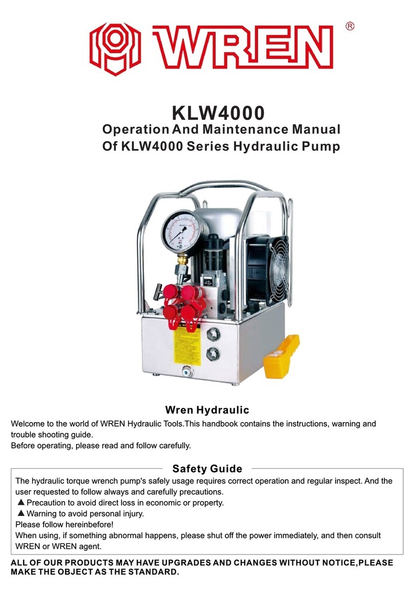
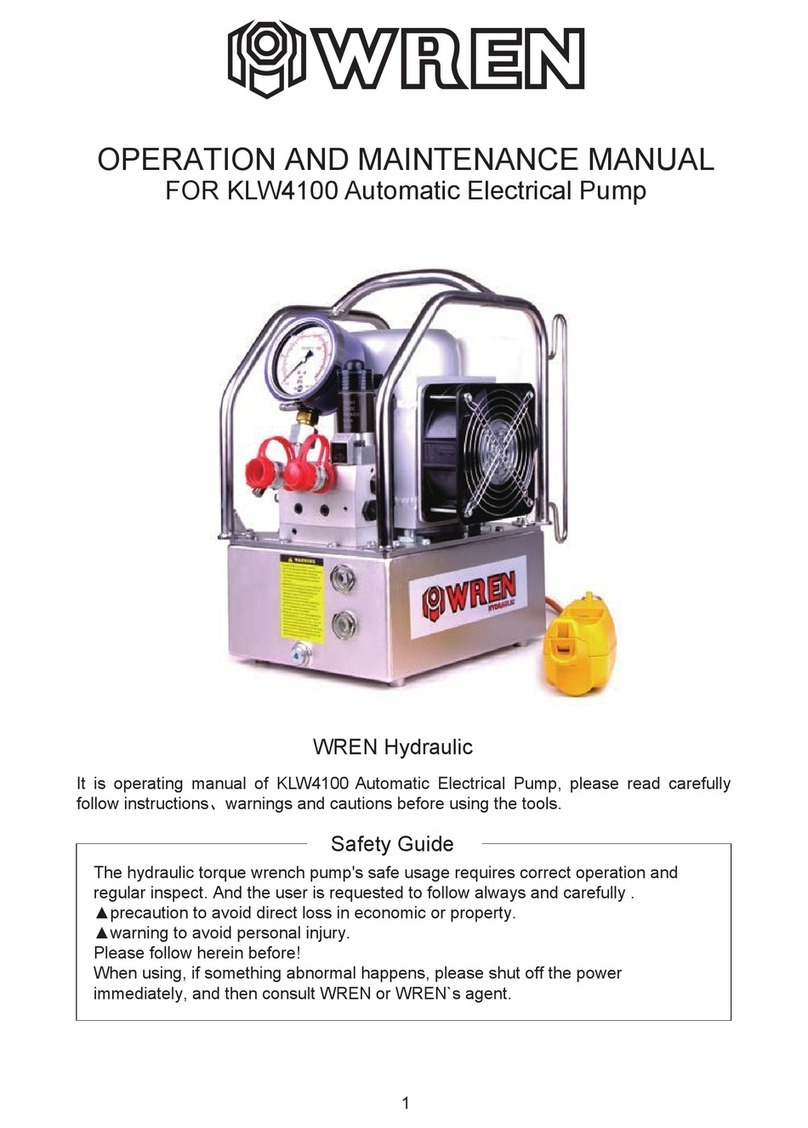
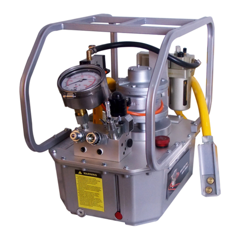
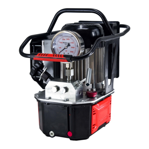
Wren KLW4000N Series User manual

Operating manual for the KLW4000N Series air hydraulic pump. Please read carefully and follow instructions, warnings
and cautions before use.
Operation and
Maintenance Manual
KLW4000N Series
Air Hydraulic Pump
Safety Guide
Your Air Hydraulic Pump requires correct operation and regular inspection as a precaution against direct loss to personnel
and property. Should anything abnormal occur during operation, please turn the pump off, disconnect it from the air
supply and consult with your Pacific / WREN agent.

2
1. Please ensure the supply is turned off before attaching the pump into a supply outlet to avoid unexpected activation of the pump.
2. Check that the incoming air supply is in good condition and regulated to the correct pressure.
3. Always ensure that all pressure is removed from the pump and all power is isolated prior to carrying out any maintenance or repair work.
4. Do not make alternations to the pump – if changes are necessary, please inform Pacific / WREN or their agent for assistance. Unauthorised
modifications may void warranty.
5. The maximum hydraulic output pressure of this pump is 70 Mpa (10,000 Psi) and this has been pre-set at the factory and must not be
increased under any circumstances.
6. If this pump is used for operating other equipment, make sure the maximum required operating pressure of the equipment does not exceed
70 Mpa (10,000 Psi). If this requirement is less than 70 Mpa, it may be necessary to reduce the maximum pressure setting to alleviate
equipment damage.
7. Take care not to over-fill the pump reservoir with oil to alleviate the possibility of a pressure increase in the reservoir, spillage and
environmental pollution.
8. Make sure the hose(s) and quick coupler(s) is (are) correctly connected and tightened before building up pressure to avoid hydraulic oil loss,
personal injury and/or equipment malfunction.
9. In the event of an oil leakage, turn the pump off immediately and correct the problem before attempting to operate again.
10. Hydraulic oil leakages can be extremely dangerous and can cause serious injuries which can sometimes be fatal. Always check the complete
system before operating and do not use if there is any doubt about the system’s integrity.
11. In the event of rapid pressure release, the lifting device or the load being operated may drop or spring open etc., depending on the operation
and may cause injuries.
12. Do not operate this equipment in the vicinity of extreme heat or fire.
13. If hydraulic oil comes in contact with your eyes, immediately flush for about 15 minutes with clean water and seek urgent medical attention.
Caution!
Please ensure only ISO grade 32 hydraulic oil is used.
Do not use the pressure regulator valve as a relief valve.
Used hydraulic oil should be carefully stored and / or disposed of in an environmentally acceptable manner.

3
Description
1. The KLW4000N Series air hydraulic pumps utilise an integrated assembly; consisting of an oil pump, control valve, oil reservoir and
air motor to provide an independent and complete hydraulic device. It has the advantages of small volume, light weight, simple robust
structure, convenient operation and high work pressure. The pump utilises high and low oil pressure and can provide a larger oil output than
conventional hand pumps. High pressure and low pressure is controlled by an unloading overflow with automatic no-load return to reduce
power consumption and oil pressure is 70 - 700 Bar (10,000 Psi max).
2. Utilises ISO grade 32 wear-resistant hydraulic oil.
3. Working environment temperature; -10 to +60oC.
4. Always use appropriate high pressure hoses and quick couplers.
5. This pump is designed for use with hydraulic products of equal pressure – please consult with Pacific / WREN or their agent if in doubt about
an application.
6. Please do not use the hydraulic pump near flames.
428
281
16
15 14
448
3
4
2
1
10
12
13
11
6
79
8
5
•
Oil reservoir
•
Bolt
•
Air motor
•
Oil water separator
1
2
3
4
•
Protecting frame
•
Quick coupler
•
Adjustable pressure regulator
•
Oil level gauge
9
10
11
12
•
Oil port
•
Screw
•
Cover plate
•
Oil port
16
15
14
13
•
Air input valve
•
Radiator
•
Air valve
•
Pressure gauge
6
7
8
5
Parts for the KLW4000N Series Pump
Description of Parts
•
Oil reservoir; contains the oil.
•
Bolt; fixings to connect motor and oil reservoir.
•
Air motor; power 4-8 Mpa.
•
Oil water separator; displaces water from oil.
•Air input valve; to control the low pressure air into the system.
•
Radiator; to dissipate heat ensuring longer operating time and
life of the pump.
•
Air valve; to output oil when the pressure is very high and control
the oil flow return. Can be used up to maximum pressure, the
thread type of the port is 1/4 NPT.
•
Pressure gauge; ranges from 0-70 Mpa to 0-10000 Psi .
1
2
3
4
5
6
7
8
•
Protection frame; protects pump assembly and can be used for
carry frame for ease of transportation.
•
Quick coupler; for ease of attachment for both tools and hoses.
•
Adjustable pressure regulator; regulates the high pressure + or – to
the set up pressure to the attached equipment.
•Oil level gauge; indicates the current oil level, when the level is below
1/3rd of the reservoir storage capacity; oil must be added.
•
Oil port; port on base of tank for removal of used oil.
•
Screw; to fix the reservoir to the pump housing.
•
Cover plate; air tight sealing for the oil reservoir.
•
Oil port; includes breather cap which has a pre-filter to prevent
access of dirt into the tank.
9
10
11
12
13
14
15
16

4
Characteristics
1. The KLW4000N is a three stage pump. The pressure relief valve is assembled in the high pressure port and low pressure port; the flow
rate is 0.8 L/m.
2. Maximum operating pressure: 70 Mpa.
3. Flow: three stage, can simultaneously use up to four torque wrenches.
4. Motor 4-8 Mpa air pressure motor.
5. Working temperature range: -10 ~ 80oC.
6. Reservoir dimension: 448 x 428 x 281mm.
7. Weight of pump excluding oil: 20.5 kg.
8. ISO grade 32 hydraulic oil.
Maintenance and Inspection
PRE-OPERATION CHECKS
1. Check if all connections are clean, secure and tight.
2. Check oil / fluid levels in the reservoir.
3. Check if the gauge is in good condition.
4. Check if all hoses are safe to use.
OPERATION CHECKS
1. Operate the pump and controls to test their function and if they are in working order.
2. Monitor the pump during the test operation for the following:
- Leaks
- Abnormal noises
- Excess vibration
- Valve condition
- Pendant or lever condition
- High temperature
3. If any abnormalities occur during testing, discontinue use and contact your Pacific / WREN agent.
AFTER OPERATION CHECKS / MAINTENANCE
1. Check if the pump is turned off and isolated.
2. Clean the pump and remove any contamination.
3. Check the fluid levels and replenish if necessary.
Warning!
Do not attempt to operate without oil.
Always keep the unit and coupling clean and free from contamination.
Never open the tank while the pump is in operation since serious injury can occur.

5
CHANGING THE HYDRAULIC OIL
The oil should be replaced once a year. However, if any of the following abnormalities occur, please replace the oil immediately.
1. If oil is contaminated in any way with dust / dirt etc.
2. If an abnormal smell occurs.
3. If the oil mixes with water and the colour of the oil has changed to milkiness.
4. If the colour of the oil has changed to black - brown.
REPLACING HYDRAULIC OIL
1. Loosen the oil filter port of the oil reservoir.
2. Remove the drain plug / screw at the front of the oil reservoir to drain the oil.
3. Clean the oil filter and reservoir.
4. Install the drain plug / screw and fill the oil reservoir with new oil as per recommendation.
Warning!
If the oil comes into contact with the eyes, please wash for at least 15 minutes with clean water and seek immediate medical
assistance. If the oil comes into contact with the skin, please wash with water and soap.
Used hydraulic oil is considered industrial waste; it should be disposed of in an environmentally friendly manner.
Operation instructions
The KLW4000N air hydraulic pump is designed for hydraulic torque wrench tools. The pump contains a 2-way, 4-position air control valve.
Port A is a high pressure point which exports the oil at high pressure and port B is a low pressure point which returns the oil at low pressure.
1. Please loosen the valve to adjust pressure before operating.
2. Connect the air line the input connector to enable starting of the pump.
3. Please press the working button on the controller and adjust the pressure unit to the required working pressure. Then release the working
button on the controller.
4. When the desired pressure is reached, the motor will stop working and the pressure will stay the same. When the pressure drops, the motor
will start to work again.
5. When the motor is working and the “Off” button on the pump is pressed, the motor will stop.The piston and pressure will stay in this position,
even if the pressure drops.
6. After operating, ensure you press the rubber button on the top of the air control valve in order to vent and release the pressure in hoses and
equipment. You can then remove the hose and add the safety cap to the quick couplers.
Turn up the pressure
2
1
•
T handle
•
Locking ring
1
2

6
MALFUNCTION REASON FOR CAUSED MALFUNCTION SOLUTION
THE PUMP DOES
NOT START
The power has not been connected properly
connected
Check the input air, switch and distribution box and
connect the air
The quick coupler has not been connected to the
correct position
Check if all connections are connected and
secured correctly
No oil in the oil reservoir Check oil level and refill if necesssary
LEAKAGE IN THE
QUICK COUPLER Check for wear of internal parts Replace the coupler or repair, using the correct
components
The relief valve is adjusted too low Check the gauge and adjust the relief valve to the
system set pressure
Oil is mixed with water Complete oil change and purge the system
Not enough oil in the reservoir Check oil level and refill if necesssary
Air present in the system Repeat operating the system with no load for several
times to eliminate the air
WHEN USING UNDER
STATIC PRESSURE,
THE PRESSURE
REDUCES SLOWLY
Check the unit connection Contact local Pacific / WREN agents for inspection
or repair
Trouble shooting for the Air Hydraulic Pump
THE SYSTEM HAS
NO PRESSURE
THE PRESSURE
DOES NOT REACH THE
REQUIRED LEVEL

7
Explosion Drawing of the KLW4000N Series Air Pump
3
4
2
1
6
7
9
8
5
10
12
11
•
Tank module
•
Pump module
•
Oil return pipe (1)
•
Petroleum pipeline
•
Oil return pipe (2)
•
Cooler module
1
2
3
4
5
6
•
Oil water separator
•
Pneumatic control valve
•
Type WE valve set module
•
Fast screwed joint
•
Straight thread joint
•
Copper fittings
7
8
9
10
11
12
Choose one

8
Explosion Drawing of the KLW4000N Series Pump Module
•
Seal – No. 1
•
Deep groove ball bearing – No. 1
•
Bearing – No. 1
•
Screw – No. 4
•
Pump flange – No. 1
•
Pump body set – No. 1
•
Unloading valve (1) – No. 1
•
Unloading valve body – No. 1/1
•
Ring – No. 1/1
•
O Ring – No. 1/1
•
O Ring – No. 1/1
•
Overpressure valve – No. 1
•
Check valve – No. 2
•
One-way valve body – No. 1/1
•
Ring – No. 1/1
•
O Ring – No. 1/1
•
O Ring – No. 1/1
•
Ring – No. 1/1
•
Unloading valve (2) – No. 1
•
Unloading valve body – No. 1/1
•
Ring – No. 1/1
•
O Ring – No. 1/1
•
O Ring – No. 1/1
•
Filter plate – No. 1
•
Screw – No. 1
•
Separation type pump body – No. 1
•
Plug – No. 10
•
Deep groove ball bearing – No. 1
•
Circlip for shaft – No. 1
•
Empty of elastic ring – No. 1
•
Deep groove ball bearing – No. 1
•
Plunger 1 – No. 2
•
Plunger 2 – No. 2
•
Plunger 3 – No. 2
•
Pin – No. 1
•
Bearing end plate – No. 1
•
Elastic washer – No. 1
1
9
2
10
9.5
10.1
10.2
10.3
10.4
9.4
9.3
9.2
9.1
7.1
7.2
7.3
7.4
11
12
13
14
15
16
17
18
19
20
21
22
23
24
3
4
5
6
7
8
•
Screw – No. 1
•
Connecting piece – No. 1
•
Screw – No. 16
•
Fitter – No. 1
25
26
27
28
29
1
6
7
8
9
10
12
13
14
15
16
18
20
17
21
21
24
25
27
28
26
22
23
19
19
19
5
11
7.1
7.2
7. 3
7. 4
44
3
2
10 .1
10.2
10.3
10.4
9 .1
9.2
9.3
9.5
9.4
9

9
Explosion Drawing of the Type WE Valve
1
2
3
3
5
6
7
8
9
4
10
12
12
16
15
14
13
11
9 .1
8 .1 8.2
8.3
9.2
3.2
7.1
7. 2
7. 3
3.1
4 .1
4.2
4.3
4.4
3.3
3.5
3.8
3.4
5 .1
5.2 5.2
5.3
3.6
3.7
9.3
•
WE connection block – No. 1
•
Plug – No. 12
•
Pilot operated directional valve – No. 2
•
Valve body – No. 1/1
•
Ring – No. 1/1
•
O Ring – No. 1/1
•
O Ring – No. 1/1
•
Ring – No. 1/1
•
Ring – No. 1/1
•
O Ring – No. 1/1
•
O Ring – No. 1/1
•
Check valve – No. 1
•
Check valve body – No. 1/1
•
Ring – No. 1
1
2
3.1
3.2
3.3
3.4
3.5
3.6
3.7
3.8
4.1
4.2
3
4
•
O Ring – No. 1/1
•
O Ring – No. 1/1
•
Pneumatic reversing valve– No. 1
•
Valve body – No. 1/1
•
O Ring – No. 2/1
•
O Ring – No. 1/1
•
Pressure gauge – No. 1
•
Pressure meter joint – No. 1
•
Pressure meter joint (G1/2) – No. 1/1
•
Pressure meter joint (G1/2) – No. 1/1
•
O Ring – No. 1/1
•
Pressure regulating valve – No. 1
•
Valve body – No. 1/1
7
8
5
6
4.3
4.4
5.1
7.1
5.2
7.2
8.1
5.3
7.3
9
10
9.1
9.2
9.3
11.1
11.2
11. 3
11
12
8
•
O Ring – No. 1/1
•
O Ring – No. 1/1
•
Pressure regulating valve – No. 1
•
Valve body – No. 1/1
•
O Ring – No. 1/1
•
O Ring – No. 1/1
•
Female quick joint – No. 1
•
Male quick joint – No. 1
•
Plug – No. 2
•
Sealing ring – No. 1
•
Elastic washer – No. 4
•
Washer – No. 4
•
Screw– No. 4
9
10
11
12
13
14
15
16
8.2
8.3
9.1
9.2
9.3

10
Explosion Drawing of the Pneumatic Control Module
•
Pneumatic motor parts – No. 1
•
Nut – No. 4
•
Fixed plate – No. 1
•
Washer – No. 4
•
Bolt – No. 4
•
Pneumatic reversing valve – No. 1
•
Cover type nut – No. 2
•
Trachea – No. 1
•
Miniature quick coupler – No. 1
•
Screw – No. 2
•
Gas control unit – No. 1
•
Inlet pipe – No. 1
•
Nut – No. 2
•
Village set – No. 2
•
Right angle type joint – No. 2
•
Three way ball valve – No. 1
•
Muffler – No. 1
•
External joint – No. 1
•
Internal and external joint – No. 1
1
2
3
4
5
6
7
8
9
10
11
12
13
14
15
16
17
18
19
3
44
2
2
1
6
77
9
8
5
5
10
12
13
13
14
14
15
15
16
17
18
19
11
7
8
9
10
11
12
PNEUMATIC SCHEMATIC DIAGRAM
In put
Flow
To air control pressure valve
To air motor
Air control lever
Air
Hand
control
valve (2)
Hand
control
valve (1)
Pneumatic control
pneumatic reversing valve

11
HYDRAULIC PRINCIPLE

HEAD OFFICE
24 Foundry Rd,
Seven Hills NSW 2147 Australia
l P+61 2 8825 6900
l F +61 2 8825 6999
l Esales@pacifichoists.com.au
QUEENSLAND
5/54 Nealdon Drive,
Meadowbrook QLD 4131
l P+61 7 3170 3800
l F+61 7 3170 3811
l Esales@pacifichoists.com.au
NEW ZEALAND
11 Druces Rd,
Manukau City 2104 Auckland
l P+64 9 263 5566
l F+64 9 263 5567
l Einfo@pacifichoists.co.nz
WESTERN AUSTRALIA
Unit 1, 31 Colin Jamieson Drive,
Welshpool WA 6106
l P+61 8 6253 1000
l F +61 8 9458 9840
l Esales@pacifichoists.com.au
Warranty
Pacific Hoists Pty Ltd warrants that all products distributed by the company are guaranteed against
any apparent fault arising from manufacturing defects caused by faulty materials and / or workmanship.
Should any part fail due to the above within 24 months after purchasing this product Pacific Hoists Pty Ltd will repair
or replace the defective part free of charge. To make a claim pursuant to this warranty, the equipment must be delivered to
Pacific Hoists Pty Ltd. Freight charges both ways are payable by the claimant and no liability is accepted for loss or damage
during transit. The claimant is required to produce the original invoice or other purchase documents as proof of purchase when
making a claim pursuant to this warranty.
The warranty does not cover the purchaser or any other person for damage, loss, normal wear or faults caused from misuse or incorrect
installation of the equipment.
To be eligible under this warranty, the equipment is required to have been installed and operated correctly by qualified personnel and has not been
subject to abuse, neglect or adjustment carried out by an unauthorized person.
This warranty may only be varied with the written approval of the Directors of Pacific Hoists Pty Ltd. In the following statement ‘Our’ means ‘Pacific
Hoists Pty Ltd’ and ‘You’ means the ‘claimant.’
Our goods come with guarantees that cannot be excluded under the Australian Consumer Law. You are entitled to a replacement or refund for
a major failure and for compensation for any other reasonably foreseeable loss or damage. You are also entitled to have the goods repaired or
replaced if the goods fail to be of acceptable quality and the failure does not amount to a major failure.
The benefits given to the claimant in this warranty are in addition to other rights and remedies under a law in relation to the goods or services to
which this warranty applies.
Table of contents
Other Wren Water Pump manuals
Popular Water Pump manuals by other brands

Scheppach
Scheppach DC100 Translation of original instruction manual

DUUN
DUUN SP200 manual

Pentair
Pentair MYERS TPL15 Installation and service manual

Wilfley
Wilfley DRYLOCK II A7 RETROFIT Installation, Operation, Maintenance and Storage Manual

JohnDow Industries
JohnDow Industries JDI-050EV manual

Alemite
Alemite 9911-HA1 Service guide