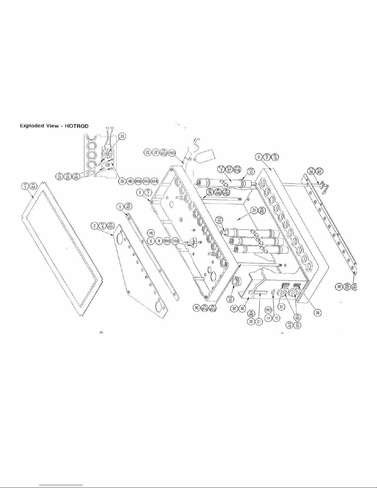
Parts Identification (continued)
The following option is available for the HOTROD:
MODEL DESCRIPTION PART NUMBER
SG-20 HR-20 Moulded sneeze guard 5736-00
SG-40 HR-40 Moulded sneeze guard 5737-00
20-D HR-20 Sneeze guard with door 3969-00
40-D HR-40 Sneeze guard with door 5691-00
The following hardware is necessary for assembly:
ITEM QTY DESCRIPTION P/N
H1 4 Screw, slotted, round hd., #6-32 by 2 1/4" pitd. sti. 81170
H2 11 Screw, slotted, pan hd., sht. mtl., #6 by 3/8", pitd. sti. 81221
H3 4 Screw, slotted, round hd., #8-32 by 3/16", pitd. sti. 81301
H4 8 Screw, slotted, pan hd., self tap, #8-32 by 3/8", pitd. sti. 81355
H5 HR20:6 Screw, slotted, hex wshr. hd., sht. mtl., #8 by 3/8" pitd. sti. 81546
HR40:8
H6 1 Screw, hex socket head, #10-32 by 1/4", steel 81633
H7 8 Screw, slotted, pan hd., sht. mtl., #10 by 3/8", pitd. sti. 81675
H8 1 Screw, slotted, truss hd., #10-32 by 1/2", pitd. sti. 81752
H9 3 Nut, tinnerman, 1/8", coated steel 84044
H10 5 Nut, hex, #10-32, pitd. sti. 84145
H11 2 Nut, hex, #10-32 (with nylon locking ring), pitd. sti. 84147
H12 2 Nut, hex, #10-24, coated steel 84224
H13 5 Washer, flat, #10, pitd. sti. 85053
H14 1 Washer, external star lock, #10, pitd. sti. 85059
H15 5 Washer, internal star lock, #10, pito. sti. 85062
H16 1 Washer, oversize flat, 3/16" ID, s/s 85072
H17 1 Washer, internal star lock, 1/2" ID, pitd. sti. 85135
H18 12 Retainer ring, E type, for 1/8" diameter shaft 89960