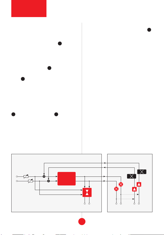
Xaoc Devices DEVA User manual

DEVA
feedback loop
commander
Model of 1970
operator’s manual rev. 1970/X/1.0

SALUT
Thank you for purchasing this Xaoc Devices
product. Deva is an expander for the
Xaoc Devices Timiszoara Eurorack digital
multi-effect module. It adds an external ste-
reo analog loop to Timiszoara, allowing you
to combine the power of digital effects with
analog processing. The left and right channels
each have a pair of send and return jacks, a
polarity switch, an analog VCA, and a volt-
-
tures a CV input and indicator for the inter-
nal clock that drives Timiszoara's DSP engine;
this allows for speeding up or slowing down
the rate of computing which affects the scale
of time and frequency, allowing for effects
INSTALLATION
The module requires 8hp worth of free space
in the Eurorack cabinet. Deva does not re-
quire connecting to bus board power, as
power is supplied from Timiszoara via the
same ribbon cable that provides communi-
cation between modules. Connect your Deva
to Timiszoara using the supplied 10-pin rib-
bon cable, paying close attention to polarity
orientation. A mark on both boards indicates
the red stripe's downward position. The ca-
ble supplied with Deva is deliberately short
to ensure low signal interference and make it
attention: never connect a power ca-
ble to any pin header on the back of
your deva; it will destroy the unit!
Both Deva and Timiszoara modules should
be fastened by mounting the supplied screws
before powering up.
MODULE OVERVIEW
two channels have separate controls and sig-
nal jacks, creating an analog signal loop that
feeds some of Timiszoara’s wet DSP output
back to its input with voltage control over the
-
tion, and optional external processing.
Two rotary level potentiometers at the
center 1are manual attenuators for the
feedback return. They have an optimized
response that rapidly increases the feed-
back when turned CW from zero while also
offering more precise control near the maxi-
mum. Their max position corresponds to the
self-oscillation point, provided the DSP code
in Timiszoara does not modify the signal
gain. Feedback depth may also be modulated
by CV via the two level cv inputs 2. Posi-
tive values of these voltages (up to +8V) in-
crease the feedback gain; however, it is limit-
ed by an internal threshold at 0dB. Similarly,
negative values (down to -8V) subtract from
the value set by the potentiometers, allowing
one to reduce the feedback to zero.
treb/bass
slider potentiometer 3as well as control
voltage (-5V to +5V) plugged into the jack
above it 4. The illuminated bi-color LED in
the slider indicates whether the high frequen-
2
module
explained

3
1
3
4
2
7
10
6
5
8
9
front panel
overview
the interface

4
cies (red) or low frequencies (green) domi-
nate in the signal.
phase toggle switches located below the
feedback level potentiometers 5allow for
The wet stereo signal from Timiszoara (be-
fore the wet/dry mix) is available in the pair
of outputs labeled send 6. Above them are
a corresponding pair of inputs labeled re-
turn 7. These pairs of jacks allow for in-
serting external processing into the feedback
loop. The return inputs are normalled to
the corresponding send outputs, thus clos-
ing the loop when nothing is patched.
The middle clock rate slider potentiometer
8and the CV input above 9control the
DSP clock rate. The bi-color LED in the slider
indicates whether the clock rate is above the
nominal 32kHz (red) or below it (green). Note
that the neutral point (nominal clock speed,
LED unlit) is located at 3/4 of the travel to
low range. At any point, you can disengage
this control by using the miniature switch 10 .
PRINCIPLE OF OPERATION
-
miszoara and Deva. The stereo pair of wet
audio signals from the DSP in Timiszoara
is fed to Deva via the ribbon cable. Deva’s
signals are buffered, and their polarity can
be changed using the front panel switches.
These signals are delivered to the pair of
front panel jacks labeled send, and also nor-
malled to the return pair of jacks. There-
fore, plugging any module or a chain of mod-
ules between sends and returns introduces
external processing into the feedback loop
while leaving it unpatched automatically
closes the loop.
The returned signals are further processed by
VCA blocks, allowing separate manual and
CV control of the feedback amount for each
channel. In addition, these VCAs feature a
soft-clipping circuit to prevent hard distor-
signal flow
Timiszoara Deva
signal outputs
signal inputs
sends returns
DSP
block
diagram
vcaphase
wet/dry mix
tilt filter

5
operating
the feedback
tion if your signal becomes too hot for the
subsequent circuits.
The last stage of processing is a voltage-con-
or the highs with a soft 6dB/octave slope.
-
miszoara via the ribbon cable and mixed at
the DSP’s input.
OPERATING THE FEEDBACK
It is important to remember that adding feed-
back around a signal processing device usual-
ly increases the signal’s strength because the
energy recycled in the loop adds to the new
incoming energy, and this process continues
-
nal increases with positive feedback around
a memoryless device. While this increase is
spread in time whenever there is a delay with-
in the loop, it is easy to see that it can quickly
run out of control and cause distortion.
Many effect programs in Timiszoara already
feature internal digital feedback as a part of
the algorithm. However, adding additional ex-
ternal analog feedback with Deva can cause a
situation where more than 100% of the pro-
cessed signal is returned to the input yielding
extreme overdrive and clipping distortion.
Therefore, start your experiments with the in-
ternal feedback at minimum (in reverb algo-
rithms, this is the size parameter) and oper-
ate only the external analog feedback in Deva.
In some cases, however, an essential part of
processing (e.g., a pitch change) is performed
within the internal digital feedback, so it
might be necessary to open the internal feed-
back enough for the processing to take effect.
Depending on the nature of some effect pro-
grams, they may gracefully respond to mod-
erate and even high amounts of feedback or
instantly blow up, producing a wall of nasty
distortion (which, depending on taste, may
be desirable or unbearable). For example,
feedback up to 99%, while reverbs (often
already operating at the edge of self-oscil-
lation) lose most of their subtlety with more
than a few percent of additional feedback.
The response of the level potentiometers
and the VCA blocks in Deva is carefully craft-
ed to allow precise feedback control near
99%. The level starts quickly from the CCW
position and reaches about 90% near half of
the turn. Note that this response is affected
by the gain of devices patched between the
send and return jacks.
60
50
40
30
20-
10
0
0 20 40 60 80 99,9
feedback amount [%]
amplitude
increase [dB]
increase of signal amplitude
with a memoryless device with
positive feedback

dsp clock rate
control
PHASE/POLARITY
When discussing the impact of feedback, there
is often a distinction between positive and
negative feedback, but this distinction only
makes sense for memoryless devices. When
there is any delay involved, various spectral
parts of the signal are shifted in phase differ-
ently; hence the whole is no longer in phase
with the original, and its inverse is no longer
anti-phase. Deva features manual phase
switches (which actually change the polarity)
feedback effect. Neither option is truly posi-
tive or negative feedback; thus, cancellation
and reinforcement of certain frequencies may
be unpredictable.
TILT FILTER
The treb/bass-
tion for timbre control using only one potenti-
ometer (and CV input). The middle position of
the slider suggests a neutral setting; however,
-
tenuates at both ends of the signal spectrum
while adding analog warmth.
Setting the slider above the middle causes the
sound thinner. For example, with a delay ef-
fect, this results in brighter echoes (note: the
A similar effect is obtained by feeding a posi-
tive voltage (up to +5V) to the CV input.
Setting the slider below the middle causes the
thus introducing darker coloration to the sig-
nal returned to Timiszoara. For example, with
a delay effect, this results in darker echos.
A similar effect is obtained by providing a neg-
ative voltage (down to -5V).
DSP CLOCK CONTROL
By default, the Spin FV-1 chip at the heart of
Timiszoara operates with a system clock of
32768Hz that determines both the sampling
rate of the signals (and bandwidth of 16kHz),
the computing speed, and the algorithms’
timing. Since the internal memory is precise-
ly 32768 words, this results in a maximum of
1 second of total delay.
Deva offers manual and voltage-controlled
over- and underclocking of the DSP chip from
2x down to 1/16 of the normal speed. With
the miniature switch in the variable posi-
tion, setting the central clock rate slider at
maximum changes the clock to over 64kHz,
signaled by the LED turning red. A CV of 5V
plugged into the jack above it achieves a sim-
ilar effect. Setting the slider at the minimum
position changes the sampling frequency to
2kHz, shown by a green LED. Using a negative
CV has a similar effect.
It is important to remember that while the
sampling and processing rate of the signal
changes with the clock, the bandwidth of the
do not change. Therefore, with low-frequency
sampling, aliasing artifacts are very audible.
For example, at the lowest speed, the effective
bandwidth is only 1kHz, so all spectral com-
6

7
expandability
& chaining
patch
examples
ponents above it will be aliased. On the other
hand, all time-based effects will sound quite
different because they will be stretched pro-
portionally.
PATCH EXAMPLES
• lo-fi grit:
you can do with your Deva is to use the DSP
clock rate control to add some nice signal
degradation to color the sound. Engage the
clock rate control (set it to variable) and
set the clock rate slider somewhere around
the middle position for a start (adjust it later
to taste). Keep the feedback level potenti-
ometers at their minimum position and enjoy
some longer and grittier delays and dirtier re-
verbs. Remember that your dry signal is unaf-
fected by the clock rate change—only the wet
• animated filtering and distortion: One
interesting idea is to use a sequencer to control
the DSP clock rate. Experiment with different
sequences. Try setting your sequencer to bi-
polar output (our Moskwa II can do that) and
combine the sequencing of the clock rate
with two medium to slow LFOs running slightly
out of phase patched into the feedback return
level cv control jacks to get some proper
panorama movement. Try this setup with
the lp_vint program from the filter bank
(cutoff around the middle, reso in the upper
half, dist almost all the way up) for a patch
that works particularly well with drums.
• crazy glitching: The setup from the pre-
vious patch also suits the glitch bank, es-
pecially the rand+grit program. Keep the
Deva settings from the animated filtering
and distortion patch and set the rate pa-
rameter of the algorithm to just above the
middle position, rand_mod a tiny bit higher,
and the buffer control slightly lower than
the leftmost slider. Overzealous glitching ga-
lore! Remember to keep the mix slider close to
the minimum position so the processed signal
doesn’t overwhelm the input audio.
• sophisticated delays: This patch explores
using Deva’s feedback loop with an external
processor. Load the ping+filt program
from the delay_ms bank. Set Deva’s feedback
return level potentiometers to a position
just below noon and the clock rate slider to
somewhere in the middle. Patch two medium
to slow LFOs running slightly out of phase into
the feedback return level cv control jacks.
Patch the left and right feedback sends to
inputs of Xaoc Devices Koszalin (or any other
stereo frequency shifter). Sequence Koszalin’s
frequency with a sequencer via the lin tz fm
input (attenuated to taste). Set the regen and
density controls somewhere above the mid-
dle position and engage the combi feedback
mode. Patch Koszalin’s up-shifted outputs
to Deva’s return jacks and enjoy this delay
effect with a continuously evolving frequency
shifted wet signal.
ACCESSORY
Our Coal Mine black panels are available for
all Xaoc Devices modules. Sold separately. Ask
your favorite retailer. •

FEATURES
Two external
feedback loops
(left and right)
with positive
and negative
feedback
treble/bass tone
control
DSP clock
control (over and
underclocking
Timiszoara's
CPU)
CV control over
everything
SPECIFICATION
Eurorack syn-
thesizer format
compatible
8hp wide, 43 mm
deep (including
the ribbon cable
and bracket)
Current drawn
from Timiszoara:
+90mA/-55mA
EASTERN BLOC TECHNOLOGIES MADE IN THE EUROPEAN UNION
ALL RIGHTS RESERVED. CONTENT COPYRIGHT ©2023 XAOC DEVICES. COPYING, DISTRIBUTION, OR COM-
MERCIAL USE IN ANY WAY IS STRICTLY PROHIBITED AND REQUIRES WRITTEN PERMISSION FROM XAOC
DEVICES. SPECIFICATIONS ARE SUBJECT TO CHANGE WITHOUT PRIOR NOTICE. EDITING BY BRYAN NOLL.
WARRANTY TERMS
XAOC DEVICES WARRANTS THIS PRODUCT TO BE FREE OF DEFECTS IN MATERIALS OR WORKMANSHIP
AND TO CONFORM WITH THE SPECIFICATIONS AT THE TIME OF SHIPMENT FOR ONE YEAR FROM THE
DATE OF PURCHASE. DURING THAT PERIOD, ANY MALFUNCTIONING OR DAMAGED UNITS WILL BE
REPAIRED, SERVICED, AND CALIBRATED ON A RETURN-TO-FACTORY BASIS. THIS WARRANTY DOES NOT
COVER ANY PROBLEMS RESULTING FROM DAMAGES DURING SHIPPING, INCORRECT INSTALLATION OR
POWER SUPPLY, IMPROPER WORKING ENVIRONMENT, ABUSIVE TREATMENT, OR ANY OTHER OBVIOUS
USER-INFLICTED FAULT.
LEGACY SUPPORT
IF SOMETHING GOES WRONG WITH A XAOC PRODUCT AFTER THE WARRANTY PERIOD IS OVER, THERE IS
NO NEED TO WORRY, AS WE’RE STILL HAPPY TO HELP! THIS APPLIES TO ANY DEVICE, WHEREVER AND
WHENEVER ORIGINALLY ACQUIRED. HOWEVER, IN SPECIFIC CASES, WE RESERVE THE RIGHT TO CHARGE
FOR LABOR, PARTS, AND TRANSIT EXPENSES WHERE APPLICABLE.
RETURN POLICY
THE DEVICE INTENDED FOR REPAIR OR REPLACEMENT UNDER WARRANTY NEEDS TO BE SHIPPED IN
THE ORIGINAL PACKAGING ONLY AND MUST INCLUDE A COMPLETED RMA FORM. XAOC DEVICES CAN
NOT TAKE ANY RESPONSIBILITY FOR DAMAGES CAUSED DURING TRANSPORT. SO BEFORE SENDING
UNSOLICITED PARCEL WILL BE REJECTED AND RETURNED!
GENERAL INQUIRIES
FOR USER FEEDBACK SUGGESTIONS, DISTRIBUTION TERMS, AND JOB POSITIONS, FEEL FREE TO CON-
FORMATION ABOUT THE CURRENT PRODUCT LINE, USER MANUALS, FIRMWARE UPDATES, TUTORIALS,
AND MERCHANDISE.
Table of contents
Other Xaoc Devices Music Pedal manuals