periods as there are steps in the pattern for the
given step. This setting is unique for each step.
In pattern mode, the steps that have been
mult pattern mode
red for div pattern mode). In step mode the
steps with active patterns are indicated by a
Default pattern settings are: div pattern
mode,
-
difference being the shorter gate duration for
the given step).
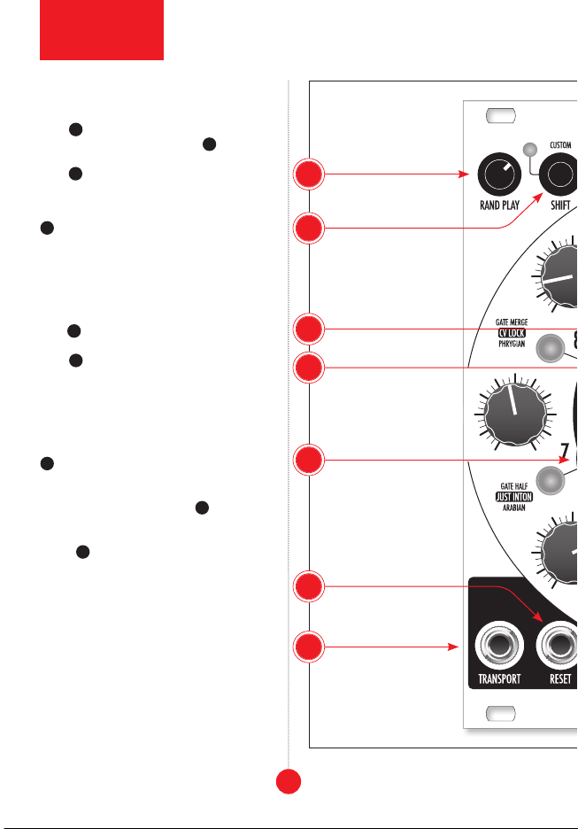
GLOBAL SETTINGS
Global settings access additional options for
detailed control over the sequencer behavior.
transport button
for one second. Active functions are indicated
by a yellow backlight on the corresponding
step 1-8 buttons.
step 1 • transport button changes the be-
havior of the transport
-
pects triggers which toggle the sequence be-
-
ior of the transport button.
step 2 • slew mode button changes the be-
step 3 • prob mode button changes the func-
tion of the probability
knob no longer increases the probability of ran-
inversions of settings activated with step 2–4
buttons in the step mode (see: “Step Settings”).
The sequence consists of 16 steps (it changes
proba-
bility
-
each step’s result can be quite different.
probability
prob-
ability
step
mode
probability knob settings between the
step mode, push
and hold the transport button and then turn
the probability knob all the way clockwise
and then all the way counterclockwise.
step 4 • brownian button changes the func-
tionality of the random play
the random play-
in the global settings by the step 4 button
the random play
step 5 • bipolar cv -
±5V.
9