- 8 - TD 252 787 467 - A
3. FUNCTIONING
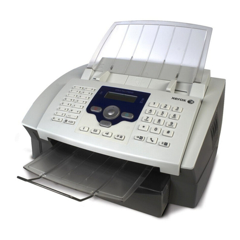
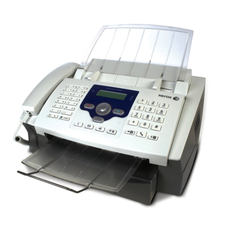
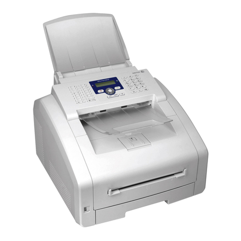
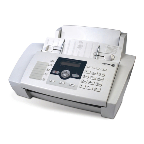
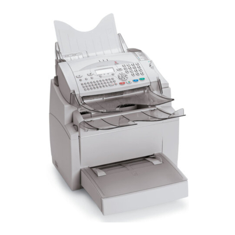
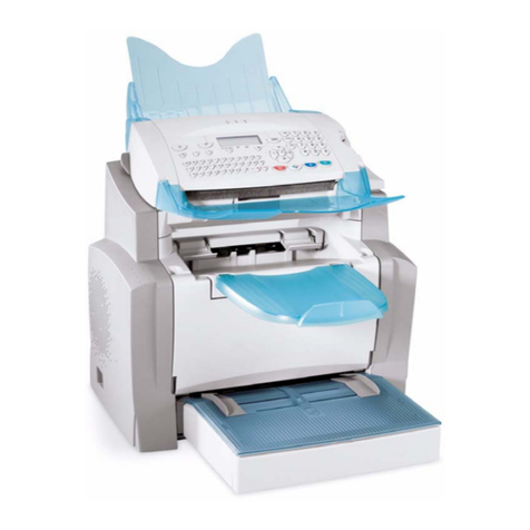
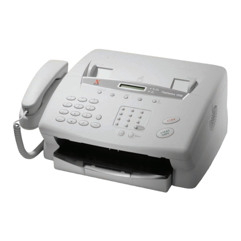
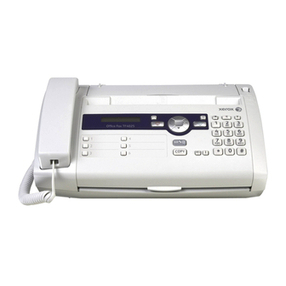
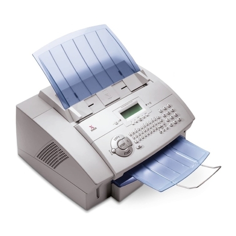
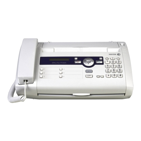
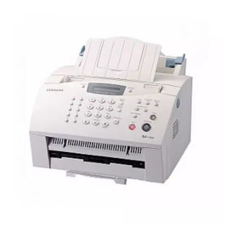
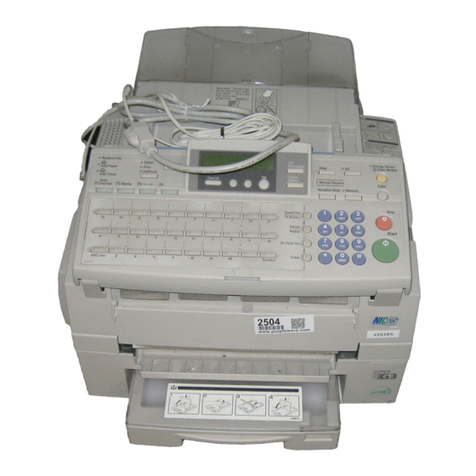
The equipment is a Group 3 multifunction fax functioning in accordance with the UIT-T
T30 recommendation.
It consists of a laser printer, a CIS (Contact Image Sensor) color sheet feeder scanner, a control panel
with a 64-key alphanumerical keyboard and an LCD screen with 2 lines of 16 characters.
Its main functions are:
• Fax transmission and reception on the switched telephone network using the V34 protocol
(max. 33.6 kbits/s) and the V17 protocol (max. 14.4 kbits/s),
• SMS (Short Message Service) transmission,
• Internet e-mail transmission and reception on the switched telephone network using the
V90 protocol,
• Photocopying,
• Local printer and scanner, via a USB interface,
• Network printer and scanner, via a local area network (LAN),
• E-mail transmission and reception on the local area network.
Note(s) : The machine does not have any facilities for managing an external telephone answering
machine connected on the same line (with a stackable plug). More generally, it is not
designed to function with any telephone equipment connected in parallel on the same
phone line. It is preferable to used a dedicated phone line for the fax: this allows to
leave the fax permanently in service and to receive communications without user inter-
vention. The fax is equipped with a standard telephone plug for connection to the
switched telephone network.
The electronics of the machine consist of a control panel board and a CPU board. For
the printer, refer to the printer section. Electrical power is supplied by the printer.
Note(s) : (for the attention of the technicians). The ECP and LAN interfaces conform to the
SELV (Safety Extra-Low Voltage, very low safety voltage) safety level.
The phone line input conforms to the TNV-3 safety level.
Before performing any intervention on the CPU board, disconnect the phone lead.
Before performing any intervention on the CPU electronic circuit board, it is also preferable to:
• Set the mains switch to the OFF position,
• Disconnect all external interconnect leads (LAN, ECP),
• Disconnect the mains lead.
3.1 CONTROL PANEL BOARD
The control panel board manages the keyboard and the LCD screen by means of a microcontroller,
which communicates with the CPU via a synchronous serial link.
The LCD screen is equipped with its own driver using COG (Chip On Glass) technology.
On this board are also installed: the scanner sensors, the external connector for the smart card and the
internal connector for the loudspeaker, these latter elements being managed by the CPU.
