XIEGU XPA12B User manual

40 February 2023 QST www.arrl.org
Product Review
Bottom Line
The XPA125B is a compact 100 W amplifier
that is designed to work with any QRP trans-
ceiver. The built-in automatic antenna tuner
adds to its operating flexibility. However,
there are technical issues that one needs to
be aware of.
Pascal Villeneuve, VA2PV
,
Reviewed by Phil Salas, AD5X
ad5x@arrl.net
Besides my main station Elecraft K-Line (K3/
KPA500/KAT500), I also own some QRP rigs
— namely Elecraft KX3, Xiegu X5105, and
Xiegu G90 transceivers — which I use pri-
marily for portable operations. The Xiegu
XPA125B 100 W amplier is an interesting
addition for those who want to use their QRP radios
as part of their higher-power xed station. While the
XPA125B is clearly designed to seamlessly interface
with the Xiegu X108G, X5105, X6100, and G90 trans-
ceivers, it will also work with any QRP rig. And an
internal wide-range automatic antenna tuner provides
antenna system exibility when necessary.
XPA125B Amplifier Technical Details
The XPA125B is powered directly from a standard
13.8 V dc power supply capable of 20 – 25 A. There
is no fan (i.e., the heavy metal case provides the nec-
essary thermal protection), and a handle on the left
side provides ease of transport. The amplier is spec-
ied to output 100 W on 160 – 10 meters, and 80 W
on 6 meters, typically with less than 5 W of drive.
Transmit and receive switching is provided by an
internal relay. There is an amplier bypass switch,
and the XPA125B is also bypassed when it is pow-
ered off. The XPA125B provides manual band
changing for non-Xiegu transceivers, and auto band
switching when used with Xiegu transceivers.
The XPA125B Display and Fault System
There is signicant control, monitoring, and display
information available on the XPA125B’s LCD front
panel display. Displayed functions include input and
output SWR, input and output RF power, voltage and
current, PA stage temperature, and band and ATU
status. Four buttons provide manual control of the
amplier: the one on the left is an
ON/OFF
power
button, the
PA
is used to switch between standby and
operating, the
BAND
button is for band selection, and
ATU/TUNE
enables the automatic antenna tuner. The
XPA125B also monitors multiple parameters to protect
Xiegu XPA125B 1.8 – 50 MHz 100 W
Amplifier
it from damage. These include high SWR (>3:1), high
current (≥25 A), high voltage (≥15 V dc), and high
temperature (≥100 °C). A fault condition suspends
normal operations, normally by bypassing the ampli-
er. Faults clear automatically when the amplier is
unkeyed. The full XPA125B specications are shown
in Table 1.
Setting Up the Amplifier
Begin by installing the 30 A fuse in the fuse holder if it
is not pre-installed. Connect the following: a ground
wire, the antenna coax into the SO-239
ANT
con-
Figure 1 — The Xiegu XPA125B rear panel.

www.arrl.org QST February 2023 41
nector, the coax from the transceiver to the SO-239
TRX
, and the power amplier (PA) key cables from the
COMM
3.5-millimeter port to your transceiver. The PA
key interface is not necessarily compatible with all
transceivers. A ground enables the amplier. How-
ever, if 3.2 V dc or more is applied to the XPA125B
PTT port, the internal processor will be permanently
damaged. The optional CE-19 interface provides
ALC, PTT, and band-changing information for the
Xiegu X5105 and G90 transceivers, and the correct
PTT interface for non-Xiegu transceivers. The Xiegu
X108 and X6100 transceivers interface directly with
the XPA125B without requiring the CE-19. If you are
using Xiegu transceivers, set the input power to 5 W,
as the ALC interface will adjust the driving power as
required. For non-Xiegu trans-
ceivers, the input power should be
initially set to 1 W. Finally, connect
the 13.8 V dc into the
DC IN
port,
and turn on the amplier by press-
ing the power button for 2 sec-
onds (see Figure 1 for the rear
panel connection ports).
Performance
Measurements
Because the XPA125B will typi-
cally be used with 5 W QRP trans-
ceivers, I tested it up to a maxi-
mum of 5 W drive, as the speci-
cations note that this is the typical
drive level needed for full power.
Table 2 details the measured
amplier input versus output. The
XPA125B display power readings
are compared to a NIST-traceable
Array Solutions PowerMaster
(input), and Mini-Circuits PWR-
6GHS+ sensor and calibrated
attenuators (output).
The rst thing I noticed was that
there was about a 0.5 to 0.6 V dc
voltage drop through the dc con-
nector on the XPA125B at the
higher current levels. There was
another 0.3 V drop along the 3-foot
dc power cable supplied with the
unit. The XPA125B power con-
nector is a six-pin Molex, but only
two tin-plated pins are used for
power. Also, the power cable
appears to be about 16 gauge, but
14- or 12-gauge wire would be
Figure 2 — The Xiegu XPA125B two-tone test with the Elecraft KX3 set at 5 W output.
Figure 3 — The Xiegu XPA125B resultant two-tone output.
more appropriate. To keep the voltage at 13.8 V dc on
the XPA125B display, I had to set my power supply to
14.6 V dc. This resulted in 100 W output on 20 meters.
Setting my power supply to 13.8 V dc resulted in the
maximum output on 20 meters dropping to 94 W. Also,
the XPA125B internal wattmeter appears centered in
accuracy on 20 meters. It reads low below 20 meters,
and high above 20 meters. So, while the internal watt-
meter appears to show that you are close to the typical
80 W specication on 6 meters, the actual power is
62 W with 5 W drive. Also, the input power monitor
reading is signicantly in error. Finally, I found that the
input and output SWR and power readings do not
work unless the amplier is on-line and being keyed.
Of course, when this is the case, the input SWR

42 February 2023 QST www.arrl.org
Table 1
Xiegu XPA125B, serial number X02DG22210070
FCC ID number 2ANLH-XPA125B.
Manufacturer’s Specifications Measured in the ARRL Lab
Frequency range: 1.8 – 30 and 160-, 80-, 60-, 40-, 30-, 20-, 17-, 15-, 12-,
50 – 54 MHz. 10-, 6-meter bands, as specied.*
Power output:
100 W PEP with 12 V ~ 15 V dc 100 W, as specied on 160 – 12 meters,
on 160 – 10 meters; 80 W on 6 meters. 79 W on 10 meters, 62 W on 6 meters
with 13.8 V dc.
Driving power required: Max 5 W. 1.8 – 54 MHz, 0.2 – 5.0 W (see Figure A).
Spurious and harmonic suppression: HF, >61 dB; 6 meters, 50 – 76 dB.
>50 dB. All bands except 6 meters meet FCC
requirements.
Third-order intermodulation distortion (IMD): 3rd/5th/7th/9th-order products
Not specied. (dB below PEP at full output):
14 MHz, –20/–29/–41/–48 dB.
See Figure B
(dB below PEP at 80 W output):
14 MHz, –28/–39/–38/–46 dB.
See Figure C.
Transmit-receive switching time: Key to RF output:
Not specied. 31 ms.
Unkey to receive: 30 ms.
Power requirements: 12 – 15 V dc, 30 A max.
Size (height, width, depth, excluding knobs, handles, and connectors):
2.8 × 6.3 × 10.3 inches. Weight: 5.86 pounds.
*In the US, the legal power limit on 30 meters is 200 W PEP output, and on 60 meters
it is an ERP of 100 W PEP relative to a half-wave dipole.
Table 2
Xiegu XPA125B Amplifier Measurements, 13.8 V dc
amplifier display. Standby: 0.16 A, key down, no drive, 2.1 A.
Band True Input XPA125B XPA125B True Gain DC Amps
Mon In Mon Out Output Act/Mea
160 M 1.0 W 0.1 W 61 W 62 W 17.9 dB 10/11
2.0 W 0.3 W 86 W 89 W 16.5 dB 11.8/14
3.0 W 0.5 W 94 W 98 W 15.1 dB 12.4/14
4.0 W 0.7 W 98 W 103 W 14.1 dB 12.6/14
5.0 W 0.9 W 100 W 108 W 13.3 dB 12.7/14
20 M 1.0 W 0 W 73 W 72 W 18.6 dB 7.9/8
2.0 W 0 W 85 W 85 W 16.3 dB 8.7/9
3.0 W 0.1 W 92 W 91 W 14.8 dB 9.3/9
4.0 W 0.2 W 95 W 96 W 13.8 dB 9.7/10
5.0 W 0.3 W 100 W 100 W 13.0 dB 10/10
10 M 1.0 W 0.1 W 68 W 63 W 18.0 dB 6.9/7
2.0 W 0.1 W 86 W 82 W 16.1 dB 8/8
3.0 W 0.2 W 91 W 87 W 14.6 dB 8.5/9
4.0 W 0.3 W 93 W 89 W 13.5 dB 8.8/9
5.0 W 0.4 W 97 W 94 W 12.7 dB 9.1/9
6 M 1.0 W 0.1 W 37 W 30 W 14.8 dB 7.5/8
2.0 W 0.3 W 52 W 44 W 13.4 dB 9.3/10
3.0 W 0.7 W 63 W 51 W 12.3 dB 10.2/11
4.0 W 1.0 W 72 W 57 W 11.5 dB 11.1/12
5.0 W 1.4 W 76 W 62 W 10.9 dB 11.8/13
always shows 1:1, as it is looking
into the input of the on-line amplier.
Finally, the gain drops as you
increase drive. This indicates that
the amplier is going into compres-
sion at the higher power levels.
This implies that you are degrading
IMD as you near the amplier’s
rated output. My KX3 has a built-in
two-tone generator, so I looked at
the barefoot KX3, and then the
KX3 driving the XPA125B to 94 W
on 20 meters (external power
supply set to 13.8 V). As you can
see in Figures 2 and 3, there is sig-
nicant degradation of IMD perfor-
mance when the amplier is used.
The XPA125B Automatic
Antenna Tuner
The XPA125B internal ATU pro-
vides manual (user-initiated) tuning.
Tuning is initiated when the
ATU/
TUNE
button is pressed for several
seconds, and 5 W of RF carrier is
applied. The ATU can be used
whether the amplier is on-line or
not. If your QRP transceiver doesn’t
include an ATU, the XPA125B will
take care of this for you. However,
as mentioned earlier, the XPA125B
SWR meters do not work unless
the amplier is on-line and keyed.
The automatic tuner will tune, but
you have no indication of the nal
SWR unless your QRP transceiver
has an SWR meter.
Tuner Matching and
Loss Measurements
Resistive matching range and loss
testing was performed with the
precision setup described in the
“Product Review” column in the
August 2012 issue of QST (see
www.arrl.org/qst-in-depth for
details). Tuning power was set at
5 W, per Xiegu recommendations.
All measured losses are subject to
the ±3% accuracy of my NIST-
traceable test equipment. The
XPA125B tuning range is specied
at 14 – 500 Ω resistive, though

www.arrl.org QST February 2023 43
Lab Notes: Xiegu XPA125B 1.8 – 50 MHz 100 W Amplifier
The Xiegu XPA125B amplier presented quite the challenge for the ARRL
Lab to test. We had originally obtained a slightly older version of this ampli-
er. It worked well enough, except for the problem that the RF power
output was low on the upper bands. This might not have been a problem in
and of itself, but when we pushed it hard to get closer to the rated power,
the transmit IMD performance was not good at all. We then found that
Xiegu had a new and improved version of the amplier, so the editors
decided to review the new unit.
When we received the new version, we saw the same problem with power
output on the 10- and 6-meter bands. Worse, this unit did not meet the
FCC limits for spurious emissions on 6 meters. We had purchased the
amplier through HRO, so we contacted them. HRO immediately agreed to
exchange the amplier for us. The replacement arrived promptly. It was a
bit low on power on the upper bands, but not as bad as the older version
had been. But the unit would not go into transmit on 80 meters and dis-
played a
LOW EFFICIENCY
error message. Again, HRO immediately
agreed to help, and we soon had a third unit. (Kudos to HRO for its excel-
lent customer service!)
Like the previous two ampliers, this amplier, again, did not meet its power
output specication on both the 10- and 6-meter bands (see Table 1). The
harmonics on 6 meters did not meet the FCC limits for spurious emissions.
If this amp is to be used on 6 meters, an external lter must be used.
The transmit IMD, measured at full available power on all applicable bands,
was marginal, but a noticeable improvement was observed when the
output power was reduced to around 80 W (see Figures B and C). If users
of this amplier want to be good neighbors on the bands, on SSB it is best
to throttle the output back from full power to achieve the cleanest signal
from the amplier on any band.
The amplier showed another unexpected anomaly. The input power was
reading signicantly low on the amplier’s input power meter compared to
the input power measured on the Lab’s wattmeter. For example, on 20
meters, the input power read 0.5 W, with an input power of 5 W measured
using an external wattmeter. The amplier is specied for an input power of
5 W, so to prevent damaging the amplier with overdrive, note the setting
of your transceiver, which produces a 5 W RF output, and be sure not to
exceed that while operating with this amplier. We did not see this problem
on the other ampliers we tested, so the unit that customers receive may or
may not have this problem, but it is something that customers should look
out for.
It might just be the bad luck of the draw, but the Lab found problems with
each of the ampliers it tested. It makes a good HF CW amplier for your
QRP rig. It can be used on FM, although it did get quite warm during test-
ing, so it would be best to throttle it back a bit. It works on SSB, but it will
be quite a bit cleaner if it is operated at about 80% of the power it will
achieve on all bands. And on 6 meters, a low-pass or band-pass lter will
be a must to avoid exceeding the FCC limits on harmonics. — George
Spatta, W1GKS, ARRL Assistant Laboratory Manager
Figure C — Xiegu XPA125B 20-meter
band IMD performance at 80 W. Third-
order products are –28 dBc, and fth-order
products are –39 dBc. Overall, throttling
back to 80 W will transmit a cleaner signal
on the bands.
Figure A — Xiegu XPA125B amplier input
versus output power.
Figure B — Xiegu XPA125B amplier
transmit IMD at 100 W on 20 meters.
Frequency (kHz)
fc
fc−4 fc−2 fc+2 fc+4
Response (dB)
–140
–130
–120
–110
–100
–90
–80
–70
–60
–50
–40
QS2302-ProdRev-B
Frequency (kHz)
fc
fc−4 fc−2 fc+2 fc+4
Response (dB)
–140
–130
–120
–110
–100
–90
–80
–70
–60
–50
–40
QS2302-ProdRev-C
0 2.0 3.0 4.01.0 5.0
0
20
40
60
80
100
120
Input (W)
Output (W)
QS2302-Prodrev-A
20 meters
6 meters
0 2.0 3.0 4.01.0
5.0
0
20
40
60
80
100
120
Input (W)
Output (W)
QS2302-Prodrev-A
20 meters
6 meters

44 February 2023 QST www.arrl.org
Table 3
Xiegu XPA125B Resistive Load and Loss Testing
VS WR/Impedance 160 M 80 M 40 M 20 M 10 M 6M
10:1/5 Ω Loss (%) 66% 28% .20% 20% .20% .28%
VSWR 2.2:1 1.6:1 1.6:1 1.4:1 1.2:1 1.5:1
8:1/6.25 Ω Loss (%) 48% 17% 9% 9% 18% 22%
VSWR 3.9:1 1.8:1 1.6:1 1.6:1 1.4:1 1.5:1
4:1/12.5 Ω Loss (%) 20% 12% 9% 9% 12% 12%
VSWR 2.2:1 1.7:1 1.4:1 1.7:1 1.8:1 1.2:1
3:1/16.7 Ω Loss (%) 16% 12% 10% 10% 10% 10%
VSWR 1.7:1 1.8:1 1.4:1 1.5:1 1.8:1 1.2:1
2:1/25 Ω Loss (%) 12% 12% 12% 8% 8% 10%
VSWR 1.7:1 1.8:1 1.8:1 1.6:1 1.5:1 1.8:1
1:1/50 Ω Bypass Loss 0% 0% 0% 0% 0% 0%
Bypass VSWR <1.1:1 <1.1:1 <1.1:1 <1.1:1 <1.1:1 <1.1:1
2:1/100 Ω Loss (%) <5% 8% 7% 7% 6% 8%
VSWR 1.6:1 1.6:1 1.6:1 1.7:1 1.6:1 1.6:1
3:1/150 Ω Loss (%) <5% 10% 10% 6% 8% 10%
VSWR 1.2:1 1.5:1 1.7:1 1.4:1 1.6:1 1.6:1
4:1/200 Ω Loss (%) <5% <5% <5% <5% <5% 8%
VSWR 1.1:1 1.4:1 1.6:1 1.5:1 1.6:1 1.2:1
8:1/400 Ω Loss (%) 15% 6% 6%. 10% 11% 12%
VSWR 2:1 1.5:1 1.6:1 1.6:1 1.5:1 1.1:1
10:1/500 Ω Loss (%) 20% <5% <5% 12% 26% 28%
VSWR 2.5:1 1.4:1 1.4:1 1.3:1 1.4:1 1.3:1
I went outside the low range for
these tests (see the results in
Table 3).
The XPA125B couldn’t match
extreme resistive impedances on
160 meters. However, it was able to
provide matches on all other bands,
though the losses could be high in
some cases. Also, I often had to
force a re-tune several times to
achieve an SWR less than 2:1, as
measured by my external SWR
meter (the XPA125B internal SWR
meter is inoperative). The XPA125B
antenna tuner does not have any
memories, so you must re-tune
each time you change frequencies,
depending on the mismatch. When
the tuned match is greater than 2:1,
there is no indication of tuning
failure, though the PA will fault if the
SWR is greater than 3:1.
Operating
I was able to test the XPA125B with
my Xiegu G90, Xiegu X5105, and
Elecraft KX3, and a QRP Labs
QCX-mini 20-meter transceiver. I
used the optional CE-19 interface
with the Xiegu radios, and it worked
well by providing keying and auto-
matic band changing for the
XPA125B. The XPA125B control
interface is a miniDIN6 connector,
so I built interface cables for the
KX3 and the QCX-mini using a mini-
DIN6P cable. The KX3 keys the
XPA125B directly. As the QCX-mini
PTT output is 5 V dc on transmit,
and 0 V dc on receive, I originally
built a special interface for this.
However, as the QCX-mini only
operates full break-in, this was a
problem due to the slow transmit/
receive relay in the XPA125B. So,
I just made a manually switched
amplier keying cable for when
I used this radio.
My HF antenna is a 43-foot vertical,
and the XPA125B autotuner easily
handles the SWR on 60 – 10
meters. I made one SSB contact on
20 meters and received a good
audio report. However, I refrained
from making additional SSB con-
tacts due to the high IMD when run-
ning full power. I felt much better
using CW and made several con-
tacts with each of my four QRP rigs
on 40, 30, and 20 meters.
Conclusion
The XPA125B is a compact 100 W
amplier that integrates perfectly
with Xiegu transceivers and, to a
slightly lesser extent, with virtually
all other QRP transceivers. The
internal antenna tuner provides all
the antenna system exibility most
hams will ever need. However,
there are several items to consider:
The Good — The XPA125B is com-
pact and rugged, requires no fan,
monitors many parameters, and is
well protected.
The Bad — The XPA125B doesn’t
meet its typical output power level
specication on 10 and 6 meters.
Also, the input voltage must be set
almost 1 V dc higher in order to
meet the typical power output spec-
ication on the other bands. And
the input power and input SWR
readings are useless.
Additionally, the XPA125B seriously
degrades the IMD performance of
the driving transceiver. Lastly, the
XPA125B does not meet FCC spec-
tral output requirements on 6
meters (an external low-pass lter
would be needed).
Manufacturer: Xiegu. Distributed
and supported in the US by select
US distributors. Price: $619.95;
CE-19 Expansion Port, $34.95.

www.arrl.org QST February 2023 45
Table 3
Xiegu XPA125B Resistive Load and Loss Testing
VS WR/Impedance 160 M 80 M 40 M 20 M 10 M 6M
10:1/5 Ω Loss (%) 66% 28% .20% 20% .20% .28%
VSWR 2.2:1 1.6:1 1.6:1 1.4:1 1.2:1 1.5:1
8:1/6.25 Ω Loss (%) 48% 17% 9% 9% 18% 22%
VSWR 3.9:1 1.8:1 1.6:1 1.6:1 1.4:1 1.5:1
4:1/12.5 Ω Loss (%) 20% 12% 9% 9% 12% 12%
VSWR 2.2:1 1.7:1 1.4:1 1.7:1 1.8:1 1.2:1
3:1/16.7 Ω Loss (%) 16% 12% 10% 10% 10% 10%
VSWR 1.7:1 1.8:1 1.4:1 1.5:1 1.8:1 1.2:1
2:1/25 Ω Loss (%) 12% 12% 12% 8% 8% 10%
VSWR 1.7:1 1.8:1 1.8:1 1.6:1 1.5:1 1.8:1
1:1/50 Ω Bypass Loss 0% 0% 0% 0% 0% 0%
Bypass VSWR <1.1:1 <1.1:1 <1.1:1 <1.1:1 <1.1:1 <1.1:1
2:1/100 Ω Loss (%) <5% 8% 7% 7% 6% 8%
VSWR 1.6:1 1.6:1 1.6:1 1.7:1 1.6:1 1.6:1
3:1/150 Ω Loss (%) <5% 10% 10% 6% 8% 10%
VSWR 1.2:1 1.5:1 1.7:1 1.4:1 1.6:1 1.6:1
4:1/200 Ω Loss (%) <5% <5% <5% <5% <5% 8%
VSWR 1.1:1 1.4:1 1.6:1 1.5:1 1.6:1 1.2:1
8:1/400 Ω Loss (%) 15% 6% 6%. 10% 11% 12%
VSWR 2:1 1.5:1 1.6:1 1.6:1 1.5:1 1.1:1
10:1/500 Ω Loss (%) 20% <5% <5% 12% 26% 28%
VSWR 2.5:1 1.4:1 1.4:1 1.3:1 1.4:1 1.3:1
Reviewed by Sean Klechak, W9FFF
To advance my Morse code skills, I’ve continuously
tried different learning methods. I eventually felt I was
ready to get on the air and make CW contacts. My
code transmission was slow, my code reception was
worse, and I barely made it through my rst few con-
tacts.
Regardless, I came out very proud of my accomplish-
ments that day. However, I have acquired a case of
“key fright” that has prevented me from getting back
on the air to practice. Instead, I have been studying,
and I am now at a crossroads. I feel I can only im-
prove so much, without someone to practice with. I
need to practice Morse code with others for a more
real-world scenario.
Building the Kit
Recently, I was introduced to the CW Hotline from
Ham Radio Solutions, a budget-friendly electronics kit
that, according to their website, is “designed to pro-
vide a way to key a remote station in CW mode, but
can also be used as a private Morse code link to
friends.” That intrigued me, as I wasn’t aware it would
work as a remote station key (two CW Hotline devices
are required). Although my main goal was to get on
the air and operate CW comfortably, I am never
opposed to putting together an electronics kit to help
me improve my soldering skills.
First, I proudly consider myself an amateur — in
every sense of the word. I am dedicated to learning
new things, experimenting with technology, and
making correctable mistakes. Electronics projects
and soldering are no different. I enjoy building these
kits, and I always gain some knowledge when assem-
bling them. The CW Hotline is sold in an assembling
kit, and recently the manufacturer started offering a
fully assembled and tested device. The kit contains all
the parts to build either the straight key or the paddle
version, and the instructions seem easy to follow.
Many people may want to practice with their own
paddle or key. For this, the CW Hotline has included a
trace on the printed circuit board (PCB) to a jack input
for your key.
There aren’t any surface-mounted parts, which is
good for new hobbyists. Altogether, there are just over
Ham Radio Solutions
CW Hotline
Bottom Line
The CW Hotline is an inexpensive and fun kit to
build. It is well designed and easy to understand,
and it provides an online portal that enables you
to connect with other learners and instructors.
This is not only an excellent way to practice CW
with people online, but with two devices it’s also
a great tool to use with friends, or even as a
remote key to activate your transceiver.
20 parts to solder in this kit, all of which attach to an
included PCB and are enclosed in a plastic case. My
experience of building this kit was relatively easy. The
kit walks through the setup and explains the use of the
CW Hotline as both a practice key and a remote key.
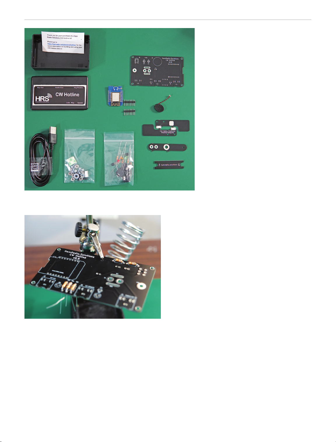
Much of the kit comes delivered in a ziplock baggie
(see Figure 4), with most of the electrical components
placed inside the black plastic electronics kit box. I
removed the components from my kit and separated
everything in my work area. This allowed me to visu-
alize the kit build. I read the online instructions rst
while conrming I had everything I needed to com-
plete the build. The case itself needs to be drilled. To
drill for the correct hole spacing and tting, you’ll need
a printer. I failed to realize this and had to go to my
local library to print the template, which is readily
available on the CW Hotline website. The manufac-
turer now offers designs for 3D-printed cases on their
website for those who wish to print their own cases
instead of drilling.
Otherwise, the kit was an easy build. A few tips to
remember: The orientation of the resistors on the
PCB doesn’t matter. The placement of the resistors,
however, does. There are ve resistors in this kit, and
the parts list clearly labels where each resistor should
be placed and provides the band color codes for
each. If you do not place the resistors in the correct
spot, you will have issues later. Subsequently, the
diodes, like the LEDs provided with the kit, have a

46 February 2023 QST www.arrl.org
During my build, I used a ux pen while
soldering the electrical components to the
PCB. I have found ux to be critical in
properly soldering components. Even with
the solder-containing change, I added
some via my ux pen. Finally, it could be
difficult to solder components on a PCB
without holding the PCB in place. I used
an inexpensive soldering stand with alli-
gator clips and a magnifying glass (see
Figure 5). This allowed me to keep the
PCB in place and look through the mag-
nifying glass to conrm that my solder-
ing joints were acceptable. Josh Nass,
KI6NAZ, uses a vice grip/block and
seems to have satisfactory results. I
would venture to say Josh’s way of
securing the PCB is sturdier and easier to
work with, and I will test that method in the
future. After about 45 minutes, I com-
pleted the build (minus the case drilling).
If you have experience in soldering, this
might take you only 30 minutes, and if
you are less experienced, don’t worry
about time. Your focus on patience and
proper techniques will be most critical. In
time, you’ll get faster and more procient with different
techniques.
I chose to build an iambic paddle. It requires a center
post so that either paddle may tap the center area,
creating a short and thus activating a dit or a dah. My
center post was not high enough off the PCB, and I
was not making electrical contact with the paddles.
Ultimately, I used an additional nut (screw) on the
center post. One nut was below the PCB, and one nut
was above the PCB, followed by a washer on top for
grounding. I have found this solution to work effi-
ciently and have yet to feel the need to tighten the
extra nut. Additionally, I have not run into any issues
with the paddles mistakenly grounding out. The best
recommendation I have is to give the extra nut a try
and determine if you like it or not. Part of the spirit of
amateur radio is tinkering and experimenting.
Three jacks are installed on the side of the kit. These
jacks are meant to hook up your own key/paddle, or
use an external speaker or a key out (see Figure 6). It
is nice to have the option to use my key, as there may
be times when I want to learn a straight key over the
paddles — not to mention the added convenience of
practicing with the paddle I’ll primarily be using. The
key out serves as a useful tool to activate a radio to
which the device is connected. Whenever I hear
Figure 4 — The contents of the CW Hotline electronics kit.
Figure 5 — Using a vice may be benecial while assembling this
kit. Here is an alligator clip holding up the PCB. The alligator clip
has rigid edges that, if placed on a trace, may cause damage.
polarity, and their orientation matters. Make sure you
read the instructions to determine the polarity. The
instructions are not included with the kit but can easily
be found on the CW Hotline website. I failed to ensure
the spacing of specic electrical components from the
PCB. Ensuring proper distance before soldering
these components is important; without the appro-
priate spacing, your built kit may not t appropriately
into your freshly drilled kit box.

www.arrl.org QST February 2023 47
this portal, I connected to VBand and started prac-
ticing my code in the “Practice Channel,” a private
channel to practice code. This is nice because I could
practice on my own or practice with QSO bot, an
automated bot that simulates regular contact on CW.
After some practice, I tried to make contact and prac-
tice code in one of the public channels. No one was
on any public channels that morning, but there I
waited, practicing calling CQ and thinking of how I
would respond. To my surprise, someone was on
within a few moments and suggested I slow down my
speed. I located the CW Hotline’s Discord server and
found it full of individuals willing to offer suggestions.
One tip was to use the pushbutton for the speed
adjustment. This easy tip had me coding at a speed I
was far more comfortable with. Then, I went back into
the Practice Channel to practice keying with the new
speed. I found the speed to be acceptable, not only
for sending but also for receiving. I chose 12 words
per minute, knowing this is below the recommended
standard when starting with code.
Linking Two Units for Remote Operations
The real fun began when I built a second kit (see
Figure 7). I chose not to solder in a straight key or
iambic paddle. This works ne if you plan on using
your key or not using the critical portion of that kit.
The second kit allows for multiple options. I can now
go through the device conguration and set a “link
key.” This link key allows for multiple devices to con-
nect directly with each other without the need for a
computer. It is meant to be unique so that no one
unauthorized is keying up your other devices. This is
important if you use the CW Hotline as a remote key
to your ham radio transceiver. I practiced sending
Morse code between units and noticed a slight delay
people discussing the CW Hotline, it is usually to
practice code over the internet. However, having the
ability to operate CW remotely with a key is intriguing.
To operate remotely and drive a connected computer,
two CW Hotline kits are required (more on this later).
CW Hotline Connections
After building the kit, I plugged the device in to see if I
let the smoke out. The CW Hotline plugs into a micro-
USB connection, which needs to have data-passing
capabilities. Not all micro-USB cables are the same. I
plugged my CW Hotline device into the computer and
navigated through the brief conguration of settings
on the CW Hotline portal (under the
CONNECT
tab at
www.hamradio.solutions/cwhotline). You can
also update the unit rmware from this web page.
Although I thought I had done everything correctly, I
heard “dah dit - dah dit dah dit,” or NC. This error
code means the device could not connect to Wi-Fi
with the settings I provided. For me, the issue was the
Wi-Fi name not being case-sensitive. With a quick
correction, a save of the locations,
and a device reboot, there it was
again: “dah dah dah - dah dit dah,”
or OK. This means the Wi-Fi is
synced correctly.
The CW Hotline user manual lists
all error codes and their meanings.
After a brief skim through the user
manual, I was able to correct the
error.
Using the CW Hotline
The next step is to go on the CW
Hotline website and access their
VBand (www.hamradio.solu
tions/vband), a different portal
from the settings conguration. At
Figure 7 — Two CW Hotline kits working together. For my second kit, I chose not to install a
straight key or paddle, as it will be used with an external key.
Figure 6 — A nearly assembled board ready to be soldered into
place. But wait! The ESP8266 shown here is placed incorrectly.
Always double-check that you have the electronics part in the cor-
rect orientation prior to soldering the components in place.

48 February 2023 QST www.arrl.org
as the signal traveled through Wi-Fi. Both units were
on the same network, so I turned my phone into a hot
spot and congured one of the CW Hotline devices
for the phone’s Wi-Fi.
Does this work over multiple computer networks? The
answer is yes. After that, I didn’t notice any additional
delay being on the same network. This is not only an
excellent key to practice with people or QSO bot on
VBand, but also (with two devices) a great tool to use
with friends, or even remotely as a key to activate
your transceiver.
Conclusion
The CW Hotline was a great kit to build. It provided
me with hours of educational value — from building
out the kit, conguring the ESP8266 to work with
VBand, and directly communicating with other CW
Hotline kits for the purpose of practicing Morse code,
to utilizing it to work as a key while operating away
from my station. At $50 per kit, it is well designed and
easy to understand, and it provides an online portal
that enables you to connect with other learners and
instructors. I highly recommend this kit to clubs
looking for a build with a purpose. After building, club
members can practice together until they feel more
procient in getting on the air. Plus, this kit is entry-
level, so it should be straightforward for beginners to
learn a variety of tasks, including soldering and Morse
code. Since building this kit and using it in different
ways, my Morse code prociency has improved, and
I expect it to continue to improve as I keep practicing
and testing myself online against others in the VBand.
Manufacturer: Ham Radio Solutions, www.
hamradio.solutions. Price: kit version: $50 each,
plus shipping; assembled version: $100 each, plus
shipping.
Reviewed by Pascal Villeneuve, VA2PV
va2pv@arrl.org
A rotator controller is an essential
accessory in an amateur radio station
that uses a directional Yagi antenna.
Most controllers are basic, and some
enable you to operate remotely. The
microHAM Antenna Rotator Controller
(ARCO) is different. First, this is an eye-
catching unit, and I must admit that this
is the best-looking rotator controller
I have ever seen. It almost looks like
another radio on the shelf. It’s bigger than the Icom IC-7300 and
has a large color touchscreen. It also has many cool features,
and operating an antenna rotator has never been easier than with
this controller.
According to the manufacturer, the ARCO controller was created
to replace all other rotator control units, and is supposed to work
with virtually any rotator. Although I was unable to test an azi-
muth/elevation type of rotator, according to the manufacturer it
features several ways of controlling azimuth or elevation heading.
While this controller is compatible with most rotators, double-
check with your local dealer to ensure full compatibility before
buying.
microHAM ARCO Smart Antenna
Rotator Controller
Bottom Line
The microHAM ARCO with the
7-inch color touchscreen is an eye-
catching antenna rotator controller,
but it’s not only a good-looking
controller for the station; it’s one of
the most advanced controllers. Its
fully customizable configurations
can ease the operations of any
complex antenna setup.

www.arrl.org QST February 2023 49
The unit is standalone, but it can be operated re-
motely via a computer, tablet, or phone (more on
this later).
Description
There are two versions of this controller. The 200 W
unit is the standard version, and the 400 W unit is
meant to be used with larger rotators. I have the
Yaesu G-450A, and the 200 W version (the reviewed
unit) is more than enough.
This rotator controller is huge, at 10.4 × 4.9 × 5.9
inches (without protrusions). It’s slightly taller than my
Icom IC-7610. On the front panel, it has a 7-inch color
touchscreen with intuitive functions. With a touch on
the map, it turns. It has an innite rotary knob to
select an exact bearing by turning in either direction.
After 3 seconds, the rotator moves to the desired
bearing. You can cancel the rotation just by pushing
the rotary knob. Under the rotary knob, there are tra-
ditional direction buttons — CCW and CW — for each
direction to manually turn the rotator holding the
selected pushbutton.
There are three LED indications on the front panel:
POWER
(amber when on),
FAULT
(normally off, red
when a fault is detected),
MOTOR
(turns green when
it’s moving), and an on/off switch.
What makes this unit different is that there are rack-
mount-style handles on each side of the front panel.
It’s useful when you need to transport it, because the
ARCO weighs 6.28 pounds.
There are many ports on the rear panel (see Fig-
ure 8). This controller can be plugged into a standard
ac outlet using the included standard power cord. If
you order from the US, you will get the 115 V ac unit.
It’s internally switchable to 240 V ac, and you can
conrm your pre-wired version by looking at the rear
panel. Above the AC
LINE
connection is a 3.5-milli-
meter (
1
⁄
8
-inch) stereo jack, which can be used to link
multiple ARCO controllers together. There’s a legacy
DB9
SERIAL
RS-232 computer control port, a
LAN
Ethernet RJ-45 port to control the unit over IP, a USB
B port (
USB
) for computer control, a USB A port (
FW
)
for keypad connection or local rmware update, and
a DB15 female (
D-SENSOR
) socket for digital position
sensors. There are two different types of rotator
connector, a 10-position removable terminal, and a
rotator connection port connected in parallel with six
conductors to connect directly to a Yaesu rotator.
There’s also a ground (
GND
) terminal bonded to the
chassis, a fuse holder, and the cooling fan that I never
heard running. The unit is always on, but goes into
standby after a while.
Optional Accessories
While I was writing this review, microHAM launched
three optional ARCO External Control (ARXC)
accessories for the ARCO controller. These options
appeared in the
SYSTEM
menu after upgrading the
controller to the latest rmware (reviewed version
3.1.E). The three optional accessories are: the ARXC
RELAY, which adds a user-programmable relay output
for antenna and polarization switches control, or mast
preamplier bypass control; the ARXC MAGNETIC,
which adds an antenna slippage watchdog and elec-
tronic compass sensor function to ARCO; and the
ARXC LoRa, which consists of two LoRA communica-
tion modules paired for a wireless link between ARCO
and ARXC modules (the operating frequency is 868
MHz). Note that this information was taken from the
manufacturer’s website, and none of the listed acces-
sories were tested in this review.
Rotator Connections and Setup
In the manual setup section, the rst thing mentioned
is “Do not connect any rotator cables to the ARCO
and make sure the power is switched to off.” They
also ask you to check that your unit is wired for your
region AC voltage. After conrming the voltage, you
can connect the power cord into the
LINE
socket.
Figure 8 — The microHAM ARCO Smart Antenna Rotator
Controller rear panel. Figure 9 — The ARCO Rotator settings menu tab.

50 February 2023 QST www.arrl.org
will nd VNC software for free on any platform,
including Windows, macOS, Linux, iOS, and Android,
so you can remotely control the ARCO on any smart
device. In my opinion, the VNC solution is the best for
remote operations, as it doesn’t require any propri-
etary software. Note that all the screen captures used
in this review were taken from my MacBook using
free VNC software. With the VNC software, you see
the same thing as the ARCO touchscreen simultane-
ously with the unit.
The last tab is
SYSTEM
, with six sub-tabs. The rst
one is
SYSTEM
(see Figure 13), and the ve others are
to set up the optional accessories (not tested in this
review). In the
SYSTEM
sub-tab, you can upgrade the
ARCO rmware directly if the unit is connected to the
internet. From there you touch the
LOAD
button to see
if there’s new rmware available. A pop-up screen will
open and show you the currently running and latest
available versions. To upgrade, there will be another
LOAD
button beside the version. Touching it will auto-
matically download the new version and upgrade the
device.
Figure 10 — The ARCO GENERAL settings menu tab.
Figure 11 — The ARCO APPEARANCE settings menu tab.
Before connecting your rotator to the controller,
ensure you have the correct pinout for your specic
model. If you’ve just installed a new rotator, you will
need to do a rotator centering. Everything is well
explained in the manual. If you’re just swapping a
controller of an existing rotator, you can skip the cen-
tering procedure. The next step is the calibration pro-
cedure. This is to ensure that the controller knows
where the limits are for each direction.
After turning on the ARCO, it may take a few moments
to boot. It’s less than 10 seconds when a rotator is
connected. At the bottom left of the screen, there’s a
gear logo that you just touch to enter the settings
menu. To set up your rotator, you will need to go to the
ROTATOR
tab. You can see my settings in Figure 9.
The settings menu has six tabs. The rst one
(
GENERAL
) is for setting up your location with your
grid square, the distance unit (kilometers or miles),
time and date, the screensaver, the park position, and
a few control options (see Figure 10).
The second tab is
APPEARANCE
, which has ve sub-
tabs (see Figure 11). In the rst sub-tab (
GLOBAL
), you
can set your preferred look of the display. You have a
day and night brightness adjustment, two background
settings (light and dark — I prefer the dark look), and
a few heading settings. The four other sub-tabs are
for the map customizable presets (more on this later).
In the
HEADING
tab, you will nd two sub-tabs, one
for the calibration and the other to dene three indi-
vidual antennas installed on the same rotator (see
Figure 12). You can also set the mounting offset of
the additional antennas versus the main antenna
(antenna #1).
The
LAN
tab is for setting your IP network. You can
remotely control this unit via any VNC software. You
Figure 12 — The ARCO HEADING (calibration) settings menu tab.

www.arrl.org QST February 2023 51
Operating the ARCO Controller
The front panel touchscreen is very intuitive. Just
touch somewhere on the map, and 3 seconds later it
will turn. You can congure up to four different cus-
tomizable maps in the
APPEARANCE
setting tab.
Having different maps depending on your operation is
very useful. With the different altitude views, you can
see the full world map (at 12,000 miles altitude) for
chasing DX on 20 meters, but you may want to see
only the North American continent while operating on
6 meters (2,400 miles altitude), or a low altitude view
for 2 meters operation (300 miles altitude). The alti-
tude is completely customizable. You can toggle
between your customized maps by touching the
MAP
ZOOM
on the touchscreen (see Figure 14). It’s better
to set up the four presets in advance, as they will be
recalled instantaneously, because generating a new
map can take about 1 minute.
You can use the innite rotary knob to select an exact
bearing manually by turning in either direction. After 3
seconds, the rotator will move in the desired direction
to the selected bearing. You can cancel the rotation
by pushing the rotary knob. Under the rotary knob,
there are traditional direction buttons — CCW and
CW — for each direction to manually turn the rotator.
Touching the azimuth number on the top right of the
screen will bring you to the
HEADING DIAL SCREEN
,
which allows you to enter the desired heading with
the large on-screen keypad (see Figure 15). It also
allows you to set the heading based on your location
to a specic DXCC country or prex, or particular
WAZ or ITU zone, to turn your antenna in the proper
direction. Touching the
NEW
azimuth will toggle
between the short and long path bearing. It shows
that this controller was designed with the DXers in
mind, as it’s complete and easy to operate.
You can program six memory presets that can be
recalled just by touching them on the touchscreen.
Figure 13 — The ARCO SYSTEM settings menu tab. Figure 14 — The main screen map recall for dierent
customizable altitude views.
Figure 15 — The HEADING DIAL SCREEN allows you to enter the
desired heading with the large on-screen keypad. It also allows
you to set the heading for the QRA locator by specic DXCC
country or prex, or particular WAZ or ITU zone, to turn your
antenna in the proper direction.
You also personalize the memory name. For
example, I have one named “PARK,” which I use to
place my antenna so it will be best positioned for the
lesser wind load against my QTH-predominant wind
direction. But even if I forget to park my antenna man-
ually, I programmed the controller to automatically
park to the correct bearing after a certain time (pro-
grammable between 1 and 99 hours; see Figure 10).
In Conclusion
This may seem like a long review for an antenna
rotator controller, and I didn’t cover everything the
ARCO controller can do. This is a complex unit, but it
makes your operations very simple, and I just love it. I
have used this unit for the past 7 months without any
issues or bugs, so this one is a keeper for me.
Manufacturer: microHAM, Maticna 28, Galanta,
92401, Slovak Republic,
www.microham.com
. Price:
$799.99 for the 200 W version (as reviewed), $899 for
the 400 W version. Available for purchase in the US
via DX Engineering, www.dxengineering.com.
Table of contents
Other XIEGU Amplifier manuals
Popular Amplifier manuals by other brands

Mosfet Power
Mosfet Power Crossfire CFA142 installation manual

Peavey
Peavey M-4000 operating instructions

ATI Audio
ATI Audio DA206 Operating and maintenance manual

Extron electronics
Extron electronics DA2 HD 4K PLUS Setup guide

McIntosh
McIntosh MHA150 owner's manual

Bose
Bose FreeSpace IZA 2120-LZ Installation and operation guide

Marshall Amplification
Marshall Amplification DSL100HR owner's manual

Network Electronics ASA
Network Electronics ASA Flashlink DA-T140 user manual

AWINIC
AWINIC AW8155B manual

Electroline
Electroline DROPAmp EDA-FT Series installation instructions

Kustom
Kustom KMA35X DFX owner's manual

ELPRO
ELPRO SD104 manual