Xoop Lighting EL 150.TW User manual

EL 150.TW
USER MANUAL

Dimensions
All dimensions are in millimeters
1.0
106
136 336
206

2.0
The following symbols are used to identify important safety information on the product and in this manual:
WARNING!
Read the safety precautions in this section before
installing, powering, operating or servicing this
product
DANGER!
Safety hazard.
Risk of severe
injury or death.
DANGER!
Hazardous
voltage. Risk of
lethal or severe
electric shock.
WARNING!
Fire hazard.
WARNING!
LED light
emission. Risk of
eye injury.
WARNING!
Burn hazard. Hot
surface. Do not
touch.
WARNING!
Wear protective
eyewear.
WARNING!
Refer to user
manual.
Warning! Risk Group 3 (high risk) LED product according to EN 62471. Do not look into the beam at a distance
of less than 3 meters from the front surface of the product. Do not view the light output with optical instruments
or any device that may concentrate the beam.
This product is for professional use only. It is not for household use.
This product presents risks of severe injury or death due to fire and burn hazards, electric shock and falls.
Read this manual before installing, powering or servicing the fixture, follow the safety precautions listed below and
observe all warnings in this manual and printed on the fixture. If you have questions about how to operate the fixture
safely, please contact your supplier.
PROTECTION FROM ELECTRIC SHOCK
lDisconnect the fixture from AC power before removing or installing any cover or part and when not in use.
lAlways ground (earth) the fixture electrically.
lUse only a source of AC power that complies with local building and electrical codes and has both overload and
ground-fault (earth-fault) protection.
lBefore using the fixture, check that all power distribution equipment and cables are in perfect condition and rated for
the current requirements of all connected devices.
lPower input and through out cables must be rated 16A minimum, have three conductors 1.5 mm² minimum
conductor size and an outer cable diameter of 5 - 15 mm . Cables must be hard usage type and heat-resistant to 90°
C minimum.
lUse only cable connectors to connect to power input sockets. Use only cable connectors to PowerCON PowerCON
connect to power through put sockets.
lIsolate the fixture from power immediately if the power plug or any seal, cover, cable, or other component is
damaged, defective, deformed, wet or showing signs of overheating. Do not reapply power until repairs have been
completed.

3.0
lRefer any service operation not described in this manual to a qualified technician.
lSocket outlets used to supply the fixture with power or external power switches must be located near the fixtures and
easily accessible so that the fixtures can easily be disconnected from power.
PROTECTION FROM BURNS AND FIRE
lThe exterior of the fixture becomes hot during use. Avoid contact by persons and materials.
Allow the fixture to cool for at least 10 minutes before handling.
lKeep all combustible materials (e.g. fabric, wood, paper) at least 100 mm away from the fixture.
lKeep flammable materials well away from the fixture.
lEnsure that there is free and unobstructed airflow around the fixture.
lDo not illuminate surfaces within 200 mm of the fixture.
lDo not attempt to bypass thermostatic switches or fuses.
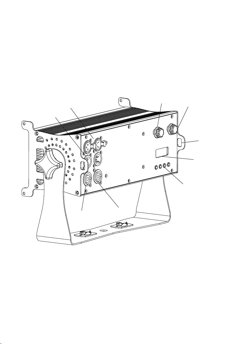
lIf you relay power from one fixture to another using power throughput sockets, do not connect more than ten the
fixture in total to each other in an interconnected chain.
lConnect only other the fixture to fixture power throughput sockets. Do not connect any other type of device to these
sockets.
lDo not connect any other type of device to these sockets.
lDo not modify the fixture in any way not described in this manual.
lDo not use fixture on a dimmer.
PROTECTION FROM INJURY
l Do not look continuously at LEDs from a distance of less than 3 meters from the front surface of the fixture without
protective eyewear such as shade 4-5 welding goggles. At less than this distance, the LED emission can cause eye
injury or irritation. At distances of 3 meters and above, light output is harmless to the naked eye provided that the
eye’s natural aversion response is not overcome.
l Do not look at LEDs with magnifiers, telescopes, binoculars or similar optical instruments that may concentrate the
light output.
l Ensure that persons are not looking at the LEDs from within 3 meters when the product lights up suddenly. This can
happen when power is applied, when the product receives a DMX signal, or when SERVICE menu items are
selected.
l Fasten the fixture securely to a fixed surface or structure when in use.
l Ensure that any supporting structure and/or hardware used can hold at least 10 times the weight of all the devices
they support.
l Allow enough clearance around the fixture to ensure that it cannot collide with an object or another fixture when it
moves.
l Check that all external covers and rigging hardware are fastened securely.
l Block access below the work area and work from a stable platform whenever installing, servicing or moving the
fixture.
lDo not operate the fixture with missing or damaged covers, shields or any optical component.

4.0
fixture overview
Control buttons
Safety cable
attachment point
dimmer switch CCT switch
LCD Display
3P & 5P DMX OUTput
3P & 5P DMX INput
AC mains power
throughput
AC mains power
input

5.0
Warning! Read “Safety Information” on page 2 before installing, powering, operating or servicing the fixture.
Before applying power to the fixture:
lCheck that the local AC mains power source is within the fixture’s power voltage and frequency ranges.
lSee “Power cables and power plug” on page 6. Install a power input connector on a suitable power PowerCON
cable.
Using for the first time
AC power
Warning! Read “Safety Information” starting on page 2 before connecting the fixtures to AC mains power.
Warning! For protection from electric shock, the fixture must be grounded (earthed). The power
distributioncircuit must be equipped with a fuse or circuit breaker and ground-fault (earth-fault) protection.
Warning! Socket outlets or external power switches used to supply the fixture with power must be
located near the fixture and easily accessible so that the fixtures can easily be disconnected from power.
Important! Do not insert or remove live connectors to apply or cut power, as this may PowerCON
cause arcing at the terminals that will damage the connectors.
Important! Do not use an external dimming system to supply power to the fixture, as this may cause
damage to the fixture that is not covered by the product warranty.
The fixture can be hard-wired to a electrical installation if you want to install it permanently, or a power plug
that is suitable for the local power outlets can be installed on the power cable.
power voltage
Warning! Check that the voltage range specified on the fixtures label matches the local AC mains power
voltage before applying power to the fixture.
The fixtures accepts AC mains power at 100-240 V nominal, 50/60 Hz. Do not apply AC mains power to the
fixture at any other voltage than specified.

6.0
power cables
Power input and throughput cables must be rated 16A minimum, have three conductors 1.5 mm² minimum
conductor size and an outer cable diameter of 5 - 15 mm. Cables must be hard usage type and heat- resistant
to 90°C minimum. In the EU the cable must be HAR approved or equivalent.
If you install a power plug on the power cable, install a grounding-type (earthed) plug that is rated 16A
minimum. Follow the plug manufacturer ’s instructions. Table 1 shows standard wire color-coding schemes
and some possible pin identification schemes; if pins are not clearly identified.
Relaying power to other devices
Warning! Do not connect more than ten fixtures in total to AC mains power in one interconnected chain.
Power can be relayed to another device via the throughput socket.PowerCON
If you daisy chain the fixtures in a chain so that they all draw AC mains power via the first fixture, certain
points must be respected:
2
• A heavy duty, three-conductor, 1.5 mm cable must be used to connect the first fixture to AC mains power.
• connectors must be used to draw AC mains power from the fixtures power throughput sockets and PowerCON
yellow connectors must be used to supply power at the fixture’s power input sockets.PowerCON
• No matter what the AC mains power voltage is, do not connect more than ten the fixture in total ( including
the first fixture) to AC mains power in one interconnected daisy chain using power input and through out
connectors.
A DMX 512 data link is required in order to control a fixture via DMX. The fixture has 3 & 5-pin XLR connectors
for DMX data input and output. The pin-out on all connectors is pin 1 = shield, pin 2 = cold (-), and pin 3 = hot
(+) Pins 4 and 5 in the 5-pin XLR connectors are not used.
tips for reliable data transmission
To connect the fixture to data:
1. Connect the DMX data output from the controller to the 3 or 5-pin XLR connector of the nearest fixture.
2. Connect the DMX output of the fixture closest to the controller to the DMX input of the next fixture and
continue connecting fixtures output to input.
Wire Color (EU models)
Wire Color (US models)
Conductor
Symbol
Brown
Black
Live
L
Blue
White
Neutral
N
Yellow/Green
Green
Ground (earth)
or
DATA LINK
Table 1 : Wire color-coding and power connections

7.0
Physical installation
Warning! The fixture must be either fastened to a flat surface such as a stage or wall, or clamped to a truss or
similar structure in any orientation using a rigging clamp.
Warning! If the fixture can cause injury or damage it if falls, attach an approved safety cable to one of the
safety cable attachment points on the base (see “Fixture overview” on page 4).
Check that all surfaces to be illuminated are minimum 200 mm. from the fixture, that combustible materials
(wood, fabric, paper, etc.) are minimum 100 mm. from the fixture, that there is free airflow around the fixture
and that there are no flammable materials nearby.
Fastening the fixture to a flat surface
The fixture can be fastened to a fixed flat surface that is oriented at any angle. Check that the surface can
support at least 10 times the weight of all fixtures and equipment to be installed on it.
Warning! The supporting surface must be hard and flat or air vents in the base may be blocked, which will
cause overheating. Fasten the fixture securely. Do not stand it on a surface or leave it where it can be moved
or can fall over. Attach a securely anchored safety cable to the safety cable attachment point (see “Fixture
overview” on page 4) if the fixture is to be installed in any location where it may fall and cause injury or
damage if the primary attachment fails.
1. Block access under the work area. Working from a stable platform, hang the fixture on the truss. Tighten
the rigging clamp.
2. Secure the fixture against clamp failure with a secondary attachment such as an approved safety cable
that is rated for the weight of the fixture using one of the attachment points at the edges of the housing (see
“Fixture overview” on page 4). Do not use any other part of the fixture as a safety cable attachment point.

8.0
SETUP
Warning! Read “Safety Information” on page 2 before installing, powering, operating the fixture.
Control panel and menu navigation
The onboard control panel and backlit graphic display are used to set the fixture’s DMX address, configure
individual fixture settings (personality), read out data and execute service utilities. See “Onboard control
menus” on for a complete list of menus and commands. page 9
Using the control buttons
• To enter the menu select [MODE].
• Press [UP] and [DOWN] to scroll within a menu or adjust values.
• To enter a menu, select a function or apply a selection, press [ENTER].
• To escape a function or move back one level in the menu structure, press [MODE].
DMX address setting
The DMX address, also known as the start channel, is the first channel used to receive instructions from the controller.
For independent control, each fixture must be assigned its to a separate channel .
The DMX address can be configured by using the DMX ADDRESS menu in the control panel. For setting the
DMX address press [ENTER] before you can change the address.
• The main screen will show a 'dot' and the backlight will be switched off when a DMX signal is detected.
• The fixture is fully RDM ready. So when you are using a RDM ready console you can address the unit and
read out its complete status. For RDM functions please refer to the ANSI/ESTA E1.20-2006 standard

9.0
Onboard control menus
NO.
Main Menu
Menu level 2
Menu level 3
Remark
1
DMX
001-512
Default 001
2
MODE
2CH
1.Cool white, 2.warm white
Default : 5CH
3CH
1.Dimmer, 2.Cool white, 3.warm white
4CH
1.Dimmer, 2.Cool white, 3.warm white, 4.CCT
5CH
1.Dimmer, 2.Cool white, 3.warm white, 4.CCT,
5.Strobe
6CH
1.Dimmer, 2.Cool white, 3.warm white, 4.CCT,
5.Strobe. 6,Dimmer speed
3
SET
D.speed
Off
Default : Off
Speed 1 / Speed 2 / Speed 3 / Speed 4
D.curve
linear
Default : linear
Square (Square law)
INV Sq (INV Square law)
S-Curve
Special
KEYLOCK
ON
Password:MENU, UP, DOWN,
MENU, UP, DOWN,ENTER
OFF
REFRESH
600 / 1200 / 2400 / 4800 Hz
Default : 600 Hz
MASTER
Master
Default : Slave
Slave
4
CCT
2800K,3200K,3500K,3800K,4200K,4500K,4800K,5000K,5600K
Default : 2800K
5
INFO
VERSION
VX.XX
USAGE.T
Xxxx H
RESET
Use time reset (password)
TEMP
XXX℃
RDM.UID
xxxxxxxxxxxxx
6
FACTORY
LOAD
Please reboot power before reset takes effect!

10.0
Select dimmer switch 0-100%
Select CCT switch 2800K to 5600K white
Signal priority after boot:
1. DMX mode:
If the EL 150.TW detect an DMX signal, it will be controlled by this signal.
2. Master/Slave
The master is controlled by the dimmer switch + CCT switch and controls all connected slaves. To change a slave to
master use the onboard control menu (Set/Master/Master) or turn the dimmer switch to 0%, pause 1 sec, turn it to
100% and pause 1 sec. This function will be disabled 60 sec. after boot.
3. Stand alone / No signal
The lamp is controlled by the position of the dimmer switch & the CCT switch.
Troubleshooting:
If there are more than one master in the line, than it is possible to force the other masters to change remotely to
slaves. This could be done by turning the dimmer of the selected master to 0%, wait 1sec, turn it to 100% and wait
again 1sec. Then all other masters switch remotely to slaves.This function will be disabled 60 sec. after boot.
50
40
30
20
10
0
60
70
80
90
100
2.8K
4.2K
5.6K

DIMMER MODE
provides five dimming options (see picture below):
Output
Output
Output
Output
DMX %
LINEAR
DMX %
SQUARE LAW
DMX %
INVERSE SQUARE LAW
DMX %
S-CURVE
Output
DMX % Up DMX % Down
SPECIAL
lLINEAR – the increase in light intensity appears to be linear as DMX value is increased.
lSQUARE LAW – light intensity control is finer at low levels and coarser at high levels.
lINV Square law – light intensity control is coarser at low levels and finer at high levels.
lS-CURVE – light intensity control is finer at low levels and high levels and coarser at medium levels.
lSpecial – the light intensity was linear increase with DMX value , and light intensity control is finer at low level
with DMX values decrease , the dimmer speed will also has effect on it
Whichever DIMMER CURVE option you select, you can choose between Off or Speed 1 / 2 / 3 / 4 dimming settings:
lOff is the default setting. It gives a virtually instantaneous reaction when you dim from one intensity to another,
but dimming slowly from one intensity to another may appear slightly uneven.
lThe Speed 1 / 2 / 3 / 4 setting gives smoother dimming during slow changes in intensity, but it limits the speed of
dimming changes slightly. This makes it ideal for slow, smooth dimming, but a short time-lag may be noticeable
if you try to dim quickly from one intensity to another.
11.0

12.0
dmx protocols
2CH
Function
Value
Setting
Remark
1
Cool white
000 - 255
0 - 100%
2
Warm white
000 - 255
0 - 100%
3 CH
Function
Value
Setting
Remark
1
Dimmer
000 - 255
0 - 100%
2
Cool white
000 - 255
0 - 100%
3
Warm white
000 - 255
0 - 100%
2 channels:
3 channels:
4 CH
Function
Value
Setting
Remark
1
Dimmer
000 - 255
0 - 100%
2
Cool white
000 - 255
0 - 100%
3
Warm white
000 - 255
0 - 100%
4
CCT
000 - 255
2800k - 5600k
4 channels:
5 CH
Function
Value
Setting
Remark
1
Dimmer
000 - 255
0 - 100%
2
Cool white
000 - 255
0 - 100%
3
Warm white
000 - 255
0 - 100%
4
CCT
000 - 255
2800k - 5600k
5
Strobe
000 - 024
025 - 064
065 - 069
070 - 084
085 - 089
090 - 104
105 - 109
110 - 124
125 - 129
130 - 144
145 - 149
150 - 164
165 - 169
170 - 184
185 - 189
190 - 204
205 - 209
210 - 224
225 - 229
230 - 244
245 - 255
ON
Strobe 1 (fast → slow)
ON
Strobe 2: opening pulse (fast → slow)
ON
Strobe 3: closing pulse (fast → slow)
ON
Strobe 4: random strobe (fast → slow)
ON
Strobe 5: random opening pulse (fast → slow)
ON
Strobe 6:random closing pulse (fast → slow)
ON
Strobe 7: burst pulse (fast → slow)
ON
Strobe 8: random burst pulse (fast → slow)
ON
Strobe 9:sine wave (fast → slow)
ON
Strobe 10: burst (fast → slow)
ON
5 channels:

13.0
dmx protocols
6 CH
Function
Value
Setting
Remark
1
Dimmer
000 - 255
0 - 100%
2
Cool white
000 - 255
0 - 100%
3
Warm white
000 - 255
0 - 100%
4
CCT
000 - 255
2800k - 5600k
5
Strobe
000 - 024
025 - 064
065 - 069
070 - 084
085 - 089
090 - 104
105 - 109
110 - 124
125 - 129
130 - 144
145 - 149
150 - 164
165 - 169
170 - 184
185 - 189
190 - 204
205 - 209
210 - 224
225 - 229
230 - 244
245 - 255
ON
Strobe 1 (fast → slow)
ON
Strobe 2: opening pulse (fast → slow)
ON
Strobe 3: closing pulse (fast → slow)
ON
Strobe 4: random strobe (fast → slow)
ON
Strobe 5: random opening pulse (fast → slow)
ON
Strobe 6:random closing pulse (fast → slow)
ON
Strobe 7: burst pulse (fast → slow)
ON
Strobe 8: random burst pulse (fast → slow)
ON
Strobe 9:sine wave (fast → slow)
ON
Strobe 10: burst (fast → slow)
ON
6
Fade
000 - 255
dimmer speed (fast → slow)
6 channels:

14.0
Specifications
Physical
Length
336mm
Width
136mm
Height
206mm
Weight
3.25 kg
Optics
Light source
324 x SMD 5050
beam angle
120°
Control and Programming
Control
DMX512-A
DMX channels
2 / 3 / 4 / 5 / 6
Setting and addressing
Control panel with backlit LCD graphic display
Protocol
RDM, USITT DMX512-A
CONSTRUCTION
Color
Black
Housing
metal
Protection rating
IP 20
Installation
Orientation
Any
Minimum distance to combustible materials
100 mm. from fixture
Minimum distance to illuminated surfaces
200 mm. from fixture
Connections
AC power input
PowerCON input socket
AC power throughput
PowerCON output socket
DMX data in/out
3 & 5 pin locking XLR
Electrical
AC power
100-240 V nominal, 50/60 Hz
Maximum total power consumption
240 W
Power supply unit
Auto-ranging electronic switch mode
Power consumption, zero light output
<15 W
Cooling
active

Table of contents
Popular Dj Equipment manuals by other brands

Serato
Serato Hercules DJControl Starlight quick start guide

EuroLite
EuroLite SHOW STAND I ALU user manual

Music & Lights
Music & Lights ProLights Tribe LUMI4COMPAQ user manual

American DJ
American DJ Quick Scan Sys User instructions

ELAN Lighting
ELAN Lighting CITYCOLOR-551-UV user manual

MAGMATIC
MAGMATIC Prisma Par 50 user manual