XPND P8 User manual

Instruktionsmanual Sida 2
Inbyggnad / monterings anvisningar
Skötselråd / underhålls instruktioner
Frågor & svar / felsökning
Instruction manual Page 11
Mounting / installation instructions
Maintenance / service instructions
Questions & answers / troubleshooting
Bedienungsanleitung Seite 19
Montage / installationsanleitungen
Wartung / serviceanleitungen
Fragen & antworten / störungsbeseitigung
P8 Multikoppling
P8 Multi-Coupling
Multikupplung P8
GB
D
S
CEJN AB
Hasslumsvägen 33
S-6541 25 Skövde, Sweden
XPND
Box 2921, 187 29 Täby. Besöksadress: Kemistvägen 12

1. SÄKERHET..............................................................3
2. INSTALLATION........................................................3
2.1 Slangplatta, 16 933 0096................................3
2.2 Bussplatta, 16 933 0097.................................4
2.3 Rampplatta 16 933 0098 ................................5
3. HANDHAVANDE......................................................6
3.1 När du hämtar bussen...................................6
3.2 När du lämnar bussen ...................................7
4. FRÅGOR & SVAR / FELSÖKNING.........................8
5. UNDERHÅLL / SKÖTSEL .......................................9
6. RESERVDELSLISTA .............................................10
INNEHÅLLSFÖRTECKNING
För ytterligare FRÅGOR & SVAR, se www.cejn.com/P8
www.xpnd.se

3
S
2. INSTALLATION
2.1 Slangplatta, 16 933 0096
Vattenslangarna ansluts på kopplingarna i
mitten, där den övre (mot urtaget i platta)
är tillopp och den undre är retur ledning.
Anslutningen är utvändig gänga G 3/4” med inv.
kona. Vätskekopplingsgängan är inv. G 1/2”.
1. SÄKERHET
P8 är en multikoppling som används för att ansluta varmvatten, tryckluft samt el till parkerade
fordon.
För monteringsinstruktion och säkerhetsföreskrifter gällande el-kontakten hänvisas till el-
kontaktens egen instruktion ”MA202-def”. Monteringsanvisning gällade induktionsgivaren
åternns på dess förpackning.
Innan respektive platta monteras bör denna manual samt separata instruktioner för elkontakten
och induktionsgivare noga genomläsas. P8’n får bara installeras eller repareras av en
fackkunnig person.
Var noga med att startspärrgivaren är installerad och i funktion. Fordonet får inte startas eller
yttas med P8 inkopplad!
För ytterligare FRÅGOR & SVAR, se www.cejn.com/P8
www.xpnd.se 3

11 1 mm
+
-
4
S
2.2 Bussplatta, 16 933 0097
Bussplattan ansluts enl. följande:
5
4
3
2
1
1
2
34
5
En 7-polig kontakt medföljer
CEJN P8 multikoppling.
Varm vätska IN i bussen är den
nippel som är monterad närmast
den utbockade styrningen på
multikopplingen med RÖD
färgmarkering märkt IN. Nippeln
(hankopplingen) har en inv. G
1/2” gänga som passar till de
medföljande slang adapterarna
16 mm (5/8”) eller 19 mm (3/4”).
Startspärrgivare som är en
induktionsgivare, typ PNP (typ:
nomally closed), levereras lös och skall
monteras på ett avstånd av 11±1 mm
från plåten enl. skiss.
Tryckluft i nippel som är av
typen CEJN 320 med pys ventil.
Distansringen skall monteras på
plattans framsida. Nippelns anslutning
är inv. G 1/4” gänga som passar till
den medföljande 10 mm (3/8”) slang
adaptern.
Retur vätska i nippeln med BLÅ
färgmarkering märkt UT. Nippeln
(hankopplingen) har en inv. G 1/2” gänga
som passar till de medföljande slang
adapterarna 16 mm (5/8”) eller 19 mm
(3/4”).
För ytterligare FRÅGOR & SVAR, se www.cejn.com/P8
www.xpnd.se
4

Min 60 mm Min 60 mm
Min 20 mm Min 20 mm
136 mm
196 mm
min 320 mm
min 155 mm
115 mm
8,5 mm
76 mm
5
S
Inbyggnadsmått bussplatta
Bra placering, sörj för god arbetsergonomi
Utrymme
måste nnas
för ngrarna
Plattan monteras i fordonet
med fyra fästpunkter (Ø 8,5 mm) enl. skiss
samt med ett fritt manövreringsområde runt
nippelplatta.
► 60 mm på båda sidor
► 20 mm över och under plattan
Viktigt att hålet i bussen är
minst 320x155 mm
2.3 Rampplatta, 16 933 0098
Rampplattan monteras på ett fast underlag
med god åtkomlighet. Fästpunkterna är de
samma som för bussplattan, 16 933 0097.
Tänk på att ha en god arbetshöjd och att
man bör kunna stå rakt framför rampplattan
när man ska ”parkera” slangplattan för
återcirkulation.
Tänk på att det inte får nnas några
vassa kanter i närheten av handtagen
på sidorna.
Avstånd från nippelplatta till framkant
på bussen skall vara så litet som
möjligt.
För ytterligare FRÅGOR & SVAR, se www.cejn.com/P8
www.xpnd.se 5

6
3. HANDHAVANDE
3.1 När du hämtar bussen
FRIGÖR plattan från bussen genom att dra
åt dig den gula plattan med ngrarna på båda
sidor.
DRA UT plattan från bussen i de svarta
handtagen.
Koppla in plattan i parkeringsläget på rampen
på rampen genom att TRYCKA IN den i
rampplattan, hjälp samtidigt till att pressa
ihop plattorna med ngrarna genom att hålla i
handtagen på rampplattan.
Gul platta
Rätt positionering,
utag skall passa
mot plåttapp
För ytterligare FRÅGOR & SVAR, se www.cejn.com/P8
S
www.xpnd.se
6

7
3.2 När du lämnar bussen
FRIGÖR slangplattan från rampen genom att
dra åt dig den gula plattan med ngrarna på
båda sidor.
DRA UT slangplattan från rampen i de svarta
handtagen.
Koppla in slangplattan i bussen genom att
styra in pinnen i mitthålet och TRYCK IN
slangplattan, hjälp samtidigt till att pressa
ihop plattorna med ngrarna genom att hålla i
handtagen på bussplattan.
För ytterligare FRÅGOR & SVAR, se www.cejn.com/P8
S
www.xpnd.se 7

8
4. FRÅGOR & SVAR / FELSÖKNING
Luftkopplingen låser inte fast vid inkoppling i bussen?
Svar: Startspärrgivare är monterad för långt ut, se installation bussplatta.
Svar: Distansringen på luftnippel saknas eller är felmonterad. På framsidan av bussplattan
ska luftnippeln ha en 7 mm distansring (på tidiga modeller kan det nnas två stycken
ringar en 5 mm och en 2 mm) kontrollera att denna/dessa är korrekt monterade.
Startspärren fungerar inte!
Svar: Elkablarna är av.
Svar: Startspärrgivare är monterad för långt in, se installation bussplatta.
Slangplattan passar ej på buss-/rampplatta!
Svar: Plåten är ihopslagen så att öppningen är för liten. Bocka ut plåten eller vid behov byt
U-prol.
Plattorna är tröga att koppla in!
Svar: Vätskekopplingen bör smörjas regelbundet, se separat dokument om skötsel och
underhåll.
För ytterligare FRÅGOR & SVAR, se www.cejn.com/P8
S
www.xpnd.se
8

9
5. SKÖTSEL OCH UNDERHÅLL
Multikopplingen ska hållas ren och fri från smuts.
Slangplattan bör smörjas regelbundet varje månad eller
vid behov. Tänk på att inte överdriva fettmängden då
detta kan drar till sig och binda smuts.
Smörjnippel med fettspruta
Rymmer 200 g fett
CEJN nr 16 933 0100
Ett tryck är tillräckligt
Se mer information i separat instruktion
Fett till fettspruta 16 933 0100
Burk 500 g fett
CEJN nr 06 000 8563
För ytterligare FRÅGOR & SVAR, se www.cejn.com/P8
S
www.xpnd.se 9

10
6. RESERVDELSLISTA
Slangplatta 16 933 0096
16 567 1240 Koppling vatten, G 1/2” inv, för 3mm plåt
16 935 1149 Koppling luft CEJN 320, slang 3/8”, för 3 mm plåt
16 933 4900 Elkontakt, 7 pol, hona
06 933 5100 Plasthus elkontakt
06 933 4100 Bakdel elkontakt, buss- och slangplatta
06 933 7035 Styrpinne plast
06 933 0804 Mutter M20 till styrpinne
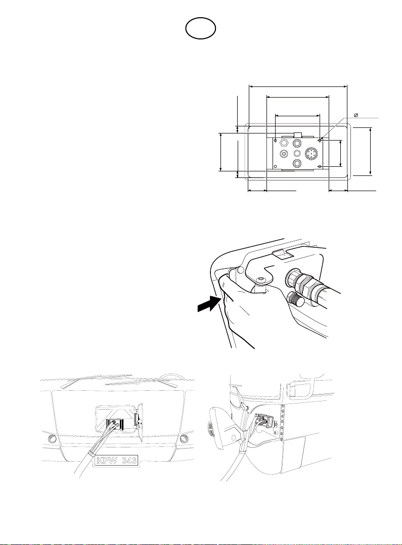
Bussplatta 16 933 0097
16 567 6240 Nippel vatten, G 1/2” inv, för 3mm plåt
16 935 1148 Nippel luft, G 1/4” (3/8” slang), för 3 mm plåt
16 933 4950 Elkontakt, 7 pol, hane
16 933 4960 Induktiv givare
06 933 2100 Plasthus elkontakt
06 933 4100 Bakdel elkontakt, buss- och slangplatta
06 933 0700 Styrbussning, buss- och rampplatta
06 933 0806 Mutter M22 till styrbussning
Rampplatta 16 933 0098
06 933 2101 Elkontakt rampplatta
Gemensama reservdelar slang-, buss- och rampplatta
09 324 2606 Låsring SGA 16 - rostfritt stål
09 933 2603 Låsring SGA 23 - rostfritt stål
06 933 2611 Låsring SGA 28 - rostfritt stål
06 933 2610 Låsring SGA 32 - rostfritt stål
06 933 2612 Låsring SGA 42 - rostfritt stål
Övrigt
16 933 0099 Smörjspruta inkl. smörjnipplar och fett
06 000 8562 Fett till 16 933 0099, 400g patron
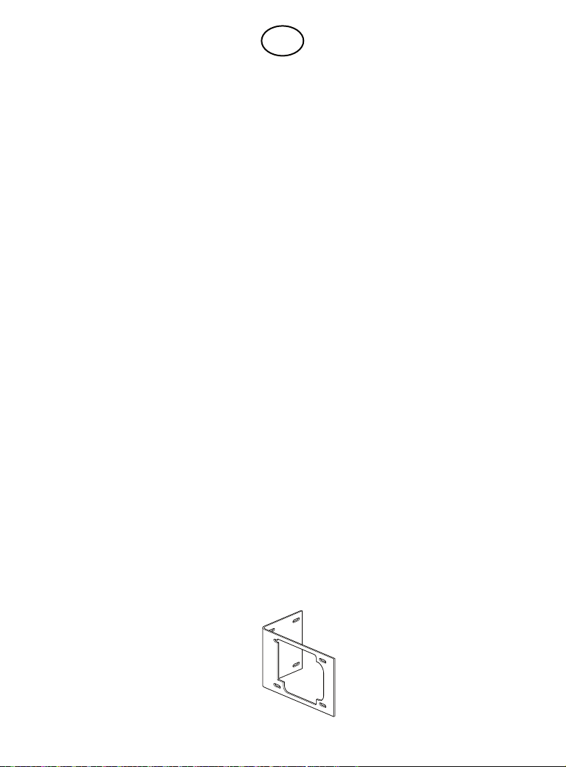
06 933 6601 Montageplåt bussplatta, L-plåt 230x140x120 mm
16 933 4910 Slanghållare / momentavlastare slangplatta
Montageplåt, för bussplatta
16 933 0097 CEJN nr 06 933 6601
S
For further QUESTIONS & ANSWERS, please go to www.cejn.com/P8
www.xpnd.se
10

1. SAFETY .................................................................12
2. INSTALLATION......................................................12
2.1 Hose plate, 16 933 0096...............................12
2.2 Bus plate, 16 933 0097.................................13
2.3 Ramp plate 16 933 0098...............................14
3. OPERATION .......................................................... 15
3.1 When picking up the bus ............................15
3.2 When leaving the bus..................................16
4.
QUESTIONS & ANSWERS/TROUBLESHOOTING
... 17
5. SERVICING/MAINTENANCE ................................18
6. SPARE PARTS LIST..............................................19
TABLE OF CONTENTS
For further QUESTIONS & ANSWERS, please go to www.cejn.com/P8
www.xpnd.se 11

12
GB
2. INSTALLATION
2.1 Hose plate, 16 933 0096
Connect the water hoses to the couplings in the
centre, with the uppermost (towards the cut-out
in the plate) being for the supply and the lower
one the return. The connection has an outside
G 3/4” thread with inner cone. The uid coupling
has an inside 1/2” thread.
1. SAFETY
P8 is a multi-coupling which is used to connect up hot water, compressed air and an electrical
supply to parked vehicles.
For installation instructions and safety regulations relating to the electrics connector, please
refer to the instructions issued by the connector manufacturer (Multi-Contact MA202-def).
Installation instructions for the inductive sensor are printed on the product packaging.
Before installing any of the plates, read through this manual carefully together with the separate
instructions for the electrics connector and inductive sensor. The P8 may only be installed or
repaired by someone who has the appropriate expertise.
Make sure that the starter inhibitor sensor has been installed and is operating properly. The
vehicle must not be started or moved with the P8 connected up.
For further QUESTIONS & ANSWERS, please go to www.cejn.com/P8
www.xpnd.se
12

11 1 mm
+
-
13
For further QUESTIONS & ANSWERS, please go to www.cejn.com/P8
GB
2.2 Bus plate, 16 933 0097
Connect the bus plate as follows:
5
4
3
2
1
1
2
34
5
A 7-pin connector is supplied
with the CEJN P8 multi-
coupling.
Hot uid IN to the bus goes to
the nipple located nearest to the
upward protruding guide on the
multi-coupling. It is colour-coded
RED and is marked IN. The nipple
(the male connector) has an inside
G 1/2” thread which ts the 16 mm
(5/8”) or 19 mm (3/4”) hose adapters
supplied.
A starter inhibitor sensor, which is a
PNP type (normally closed) inductive
sensor, is supplied separately and must
be tted at a distance of 11±1 mm from
the plate, as illustrated in the diagram.
Compressed air goes to a CEJN 320
type nipple which has a relief valve.
The spacer must be tted on the
front of the plate. The connection of
the nipple has an inner G 1/4” thread
which ts the 10 mm (3/8”) hose
adapter supplied.
Return uid exits from the BLUE colour-
coded nipple marked OUT. The nipple
(the male connector) has an inside G 1/2”
thread which fits the 16 mm (5/8”) or
19 mm (3/4”) hose adapters supplied.
For further QUESTIONS & ANSWERS, please go to www.cejn.com/P8
www.xpnd.se 13

Min 60 mm Min 60 mm
Min 20 mm Min 20 mm
136 mm
196 mm
min 320 mm
min 155 mm
115 mm
8,5 mm
76 mm
14
GB
Bus plate installation dimensions
Good positioning; ensure good ergonomics while
working
There must be
enough room
for your ngers
Fit the plate to the vehicle
using the four attachment points (Ø 8.5 mm)
as shown in the diagram, while ensuring there
is enough room around the nipple plate to
allow easy connection.
► 60 mm on both sides
► 20 mm above and below the plate
Important: the hole in the bus
must be at least 320x155 mm
2.3 Ramp plate, 16 933 0098
Install the ramp plate on a rm base which
allows good access. The attachment points
are the same as those on the bus plate,
16 933 0097.
Remember that you need a comfortable
working height and that you should be able
to stand right in front of the ramp plate when
“parking” the recirculation hose plate.
Remember that there must be no sharp
edges near the handles on either side.
The distance from the nipple plate to the
front edge of the bus must be kept to
the very minimum.
For further QUESTIONS & ANSWERS, please go to www.cejn.com/P8
www.xpnd.se
14

15
For further QUESTIONS & ANSWERS, please go to www.cejn.com/P8
3. OPERATION
3.1 When picking up the bus
RELEASE the plate from the bus by grasping
the yellow plate on each side with your ngers
and pulling it towards you.
PULL OUT the plate from the bus using the
black handles.
Attach the hose plate in its parked position on
the ramp by PUSHING it INTO the ramp plate.
This is best achieved by pressing the plates
together with the ngers while holding onto the
handles of the ramp plate.
Yellow plate
Correct positioning; the
cut-out has to t against
the projection on the plate
For further QUESTIONS & ANSWERS, please go to www.cejn.com/P8
GB
www.xpnd.se 15

16
3.2 When leaving the bus
RELEASE the hose plate from the ramp by
grasping the yellow plate on each side with
your ngers and pulling it towards you.
PULL OUT the hose plate from the ramp using
the black handles.
Attach the hose plate to the bus by guiding the
pin into the centre hole and PUSHING the hose
plate IN. This is best achieved by pressing the
plates together with the ngers while holding
onto the handles of the bus plate.
For further QUESTIONS & ANSWERS, please go to www.cejn.com/P8
GB
For further QUESTIONS & ANSWERS, please go to www.cejn.com/P8
www.xpnd.se
16

17
For further QUESTIONS & ANSWERS, please go to www.cejn.com/P8
4. QUESTIONS & ANSWERS/TROUBLESHOOTING
The air coupling will not lock in position when connecting to the bus.
Answer: The starter inhibitor sensor has been tted too far out, see the bus plate installation
instructions.
Answer: The spacer on the air nipple is missing or has been incorrectly tted. The air nipple
on the bus plate must be tted with a 7 mm spacer on the front (older versions may
have two spacers, one 5 mm and the other 2 mm). Check that the spacer(s) is/are
correctly tted.
The starter inhibitor is not working.
Answer: The electrical cables have become disconnected.
Answer: The starter inhibitor sensor has been tted too far in, see the bus plate installation
instructions.
The hose plate does not t on the bus/ramp plate.
Answer: The plate is bent, making the opening too small. Straighten the plate or replace the
U prole where necessary.
Connection of the plates feels stiff.
Answer: The uid coupling should be regularly lubricated; see the separate maintenance
and servicing instructions.
For further QUESTIONS & ANSWERS, please go to www.cejn.com/P8
GB
www.xpnd.se 17

18
The multi-coupling must be kept clean and free of
dirt. The hose plate should be lubricated regularly
each month or as needed. Remember not to apply
too much grease, as this can result in build-up of dirt.
Grease nipple with grease gun
Takes 200 g of grease
CEJN No. 16 933 0100
One press is sufcient
For more information, see the separate instructions
Grease for grease gun 16 933 0100
Can containing 500 g of grease
CEJN No. 06 000 8563
For further QUESTIONS & ANSWERS, please go to www.cejn.com/P8
GB
5. MAINTENANCE AND SERVICING
www.xpnd.se
18

19
For further QUESTIONS & ANSWERS, please go to www.cejn.com/P8
6. SPARE PARTS LIST
Hose plate 16 933 0096
16 567 1240 Coupling, water, G 1/2” inside, for 3 mm plate
16 935 1149 Coupling, air, CEJN 320, hose 3/8”, for 3 mm plate
16 933 4900 Electrics connector, 7-pin, female
06 933 5100 Plastic housing, electrics connector
06 933 4100 Rear assembly, electrics connector, bus and hose plate
06 933 7035 Guide pin, plastic
06 933 0804 Nut, M20, for guide pin
Bus plate 16 933 0097
16 567 6240 Nipple, water, G 1/2” inside, for 3 mm plate
16 935 1148 Nipple, air, G 1/4” (3/8” hose), for 3 mm plate
16 933 4950 Electrics connector, 7-pin, male
16 933 4960 Inductive sensor
06 933 2100 Plastic housing, electrics connector
06 933 4100 Rear assembly, electrics connector, bus and hose plate
06 933 0700 Guide bushing, bus and ramp plate
06 933 0806 Nut, M22, for guide bushing
Ramp plate 16 933 0098
06 933 2101 Electrics connector, ramp plate
Spare parts common to hose, bus and ramp plate
09 324 2606 Locking ring SGA 16 – stainless steel
09 933 2603 Locking ring SGA 23 – stainless steel
06 933 2611 Locking ring SGA 28 – stainless steel
06 933 2610 Locking ring SGA 32 – stainless steel
06 933 2612 Locking ring SGA 42 – stainless steel
Miscellaneous
16 933 0099 Grease gun c/w grease nipples and grease
06 000 8562 Grease for 16 933 0099, 400 g cartridge
06 933 6601 Base plate, bus plate, L plate 230x140x120 mm
16 933 4910 Hose holder/torque limiter, hose plate
Base plate, for bus plate
16 933 0097 CEJN No. 06 933 6601
GB
www.xpnd.se 19

1. SICHERHEIT..........................................................21
2. INSTALLATION......................................................21
2.1 Schlauchplatte, 16 933 0096 .......................21
2.2 Busplatte, 16 933 0097.................................22
2.3 Rampenplatte 16 933 0098 ..........................23
3. VERWENDUNG .....................................................24
3.1 Beim Holen des Busses ..............................24
3.2 Beim Zurückstellen des Busses.................25
4. FRAGEN UND ANTWORTEN/FEHLERSUCHE .... 26
5. WARTUNG UND PFLEGE..................................... 27
6. ERSATZTEILLISTE ............................................... 28
INHALT
Weitere FRAGEN und ANTWORTEN nden Sie unter: www.cejn.com/P8
www.xpnd.se
20
This manual suits for next models
3
Table of contents
Languages:
Popular Cables And Connectors manuals by other brands

Lenze
Lenze L-force EYF A Series Mounting instructions

Leviton
Leviton QuickPort Duplex 106 Specifications

LINK-MI
LINK-MI LM-SP144E-HD4K2K operating instructions

Festo
Festo NEBM-M12W8-E Series Assembly instructions

VOLTCRAFT
VOLTCRAFT 710226 operating instructions

Outwell
Outwell APUS MAINS ROLLER KIT UK instructions