XS Scuba Inspire Regulator User manual

1
www.XSscuba.com
XS Scuba Inspire Regulator Service Manual
Inspire Regulator Service Manual
Covers Inspire Regulator and Inspire Octopus

2www.XSscuba.com
XS Scuba Inspire Regulator Service Manual
Table of Contents
Introduction 2
Warnings, Cautions and Notes 2
Maintenance Schedules 3
Standard Procedures 3
Nitrox Compatibility 3
Pre-Test & Inspection Prior to Disassembly 4
Required Tools 4
Exploded Diagrams and Part Lists 6
1st Stage Disassembly Procedure 10
2nd Stage Disassembly Procedure 14
Introduction
This manual outlines manufacturer prescribed
servicing procedures for the regulator product
described within. It covers disassembly, cleaning,
inspection, reassembly, adjusting and testing of said
regulator product. This publication assumes that the
technician performing the service is experienced,
Document Change Notice (DCN)
Warnings, Cautions and Notes
Pay special attention to information provided in warnings, caution and notes that are accompanied by one of
these symbols:
WARNING indicates a procedure or situation that may result in serious injury or death
if instructions are not followed correctly
CAUTION indicates any situation or technique that will result in potential damage to the
product, or render the product unsafe if instructions are not followed correctly
NOTE is used to emphasize important points, tips or reminders
Cleaning Procedures 19
Preparing and Inspecting Parts 19
Recommended Cleaners and Lubricants 20
1st Stage Reassembly Procedure 21
1st Stage Adjusting and Testing 26
2nd Stage Reassembly Procedure 28
2nd Stage Adjusting and Testing 33
Troubleshooting Guides 35
Torque Specications 37
Test Bench Specications 37
Page # Rev. Date Revision Made
All 04/20/2017 First Release
20 12/18/2017 Source for Christo-lube MCG111 changed
mechanically inclined, is using the proper tools,
parts and procedures prescribed within. If you do
not fully understand all of the procedures outlined
in this manual, contact XS Scuba and speak with a
Technical Advisor before proceeding any further.

3
www.XSscuba.com
XS Scuba Inspire Regulator Service Manual
Maintenance Schedules
Regulators are subjected to a variety of environmental
elements that over time can affect their performance. Salt,
sand, sediment, chlorine and other chemicals all take
their toll on a regulator. Soft parts wear out and lubricants
break down and wash away. As an XS Scuba Dealer, you
are advised to inform your staff and customers that
XS Scuba regulators require servicing at least once a year.
Under certain circumstances service is required every 3-6
months. Some of those circumstances are:
1. Frequent or improper use
2. Inadequate routine freshwater rinsing
3. Regulator use in dirty or polluted waters
4. Rental use
5. Regular use in chlorinated (pool) water
Recommended maintenance schedules are based on
average use under normal conditions and assume that
recommended preventative maintenance and storage
procedures have been followed as outlined in the
XS Scuba Regulator Owner’s Manual.
Standard Procedures
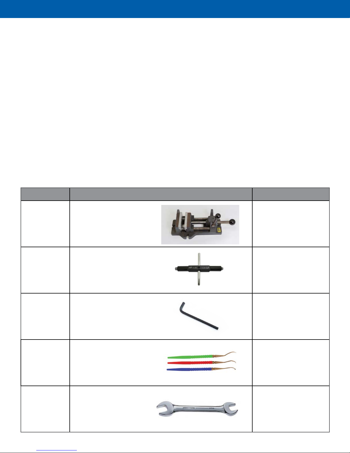
1. Preview the list of tools and parts required to perform
the prescribed service outlined in this manual. Follow
each step in the sequence provided. Have this manual
open next to you for reference. Do not rely upon
memory.
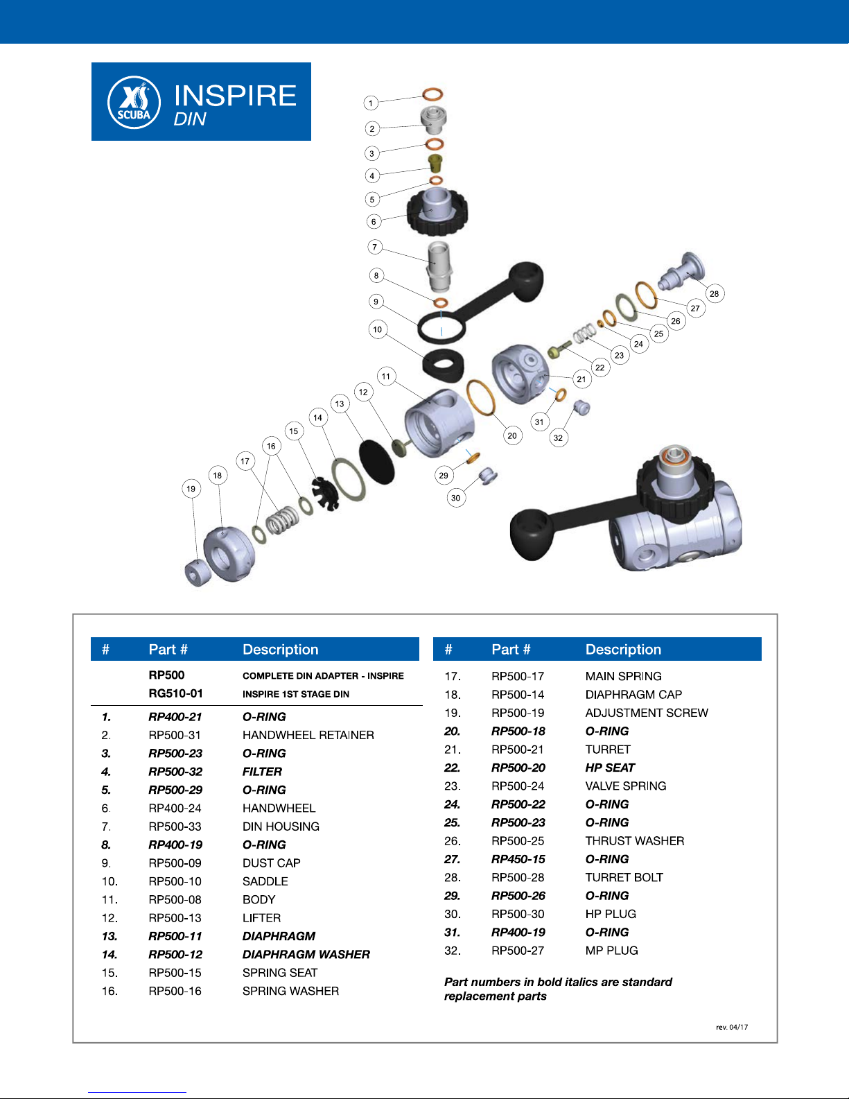
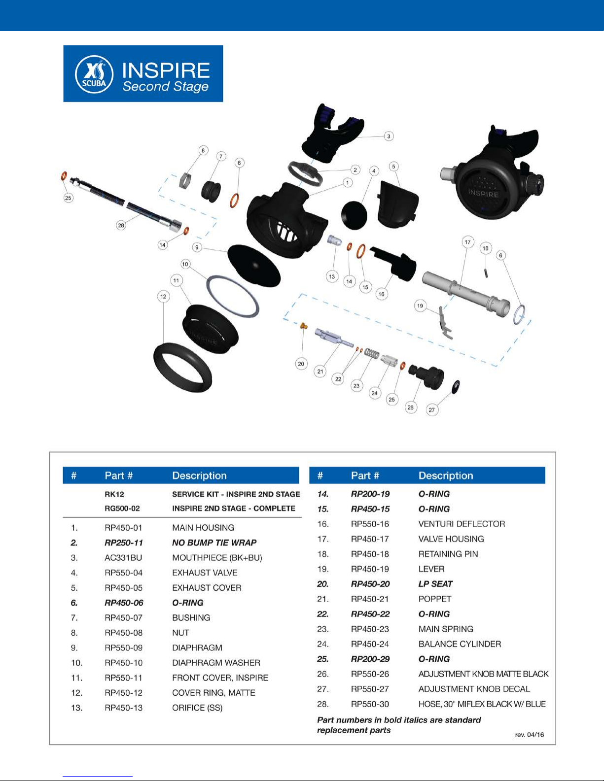
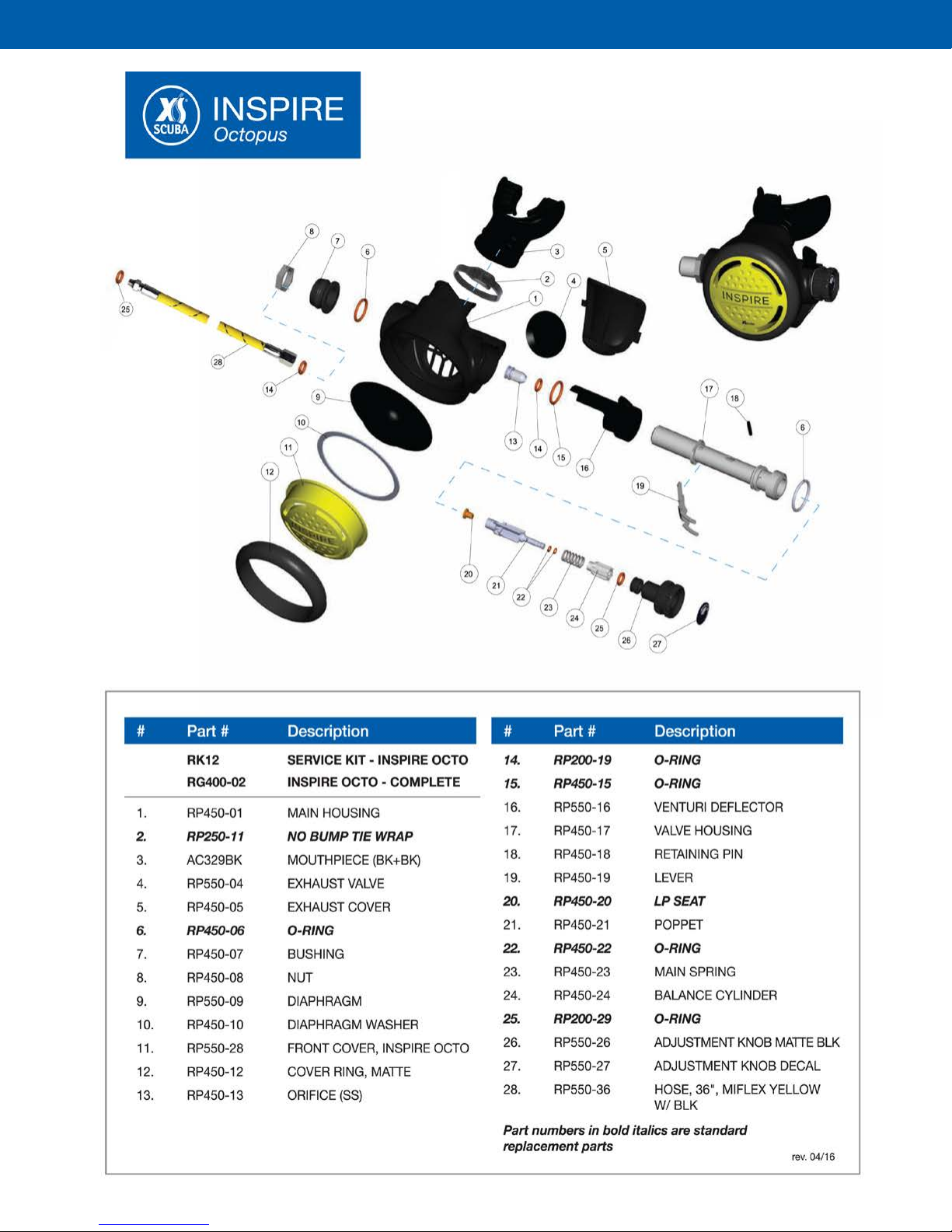
2. Numbers found in parenthesis reference the KEY
numbers in the exploded diagrams. If you are not sure
what a part is by its description, use this number to
cross reference it in the exploded diagram.
3. All regulator services should be performed on a
workbench specically set up and equipped for this
purpose. Adequate lighting and cleanliness along
with easy access to the required tools should be
considered mandatory.
4. Delicate parts, such as parts with critically machined
surfaces should be isolated from the other parts
to prevent damage, especially during the cleaning
procedure.
5. Only use factory authorized parts provided by
XS Scuba. Do not attempt to substitute other
manufacturer’s parts regardless of any similarity in
appearance. This is especially true for o-rings!
6. Do not attempt to reuse mandatory replacement
parts regardless of how much use those parts were
subjected to.
7. When reassembling, it is important to follow factory
mandated torque values using a calibrated torque
wrench. To do otherwise could lead to damage or
failure of the product.
8. Unless otherwise instructed, the following is
assumed:
a. When instructed to remove, unscrew or
loosen a threaded part, turn the part
counterclockwise. The manual abbreviates
counterclockwise with CCW.
b. When instructed to install, screw in or tighten
a threaded part, turn the part clockwise.
The manual abbreviates clockwise with CW.
9. The following abbreviations are used throughout this
manual:
a. HP = High Pressure – the pressure entering a
regulator from the cylinder e.g. 3000psi
b. MP = Medium Pressure – the pressure leaving
the rst stage traveling to the 2nd stage. Also
referred to as intermediate or interstage pressure
c. LP = Low Pressure – the pressure exiting the
2nd stage through the mouthpiece. Also referred
to as ambient pressure.
Nitrox Compatibility
XS Scuba regulator products may be safely used with
enriched air nitrox (EAN) that does not have an oxygen
content greater than 40% (EAN40), if the regulator is
properly cleaned and prepared. Properly cleaned means
that a mild detergent is used to remove hydrocarbons
such as compressor oils. Properly prepared means that
only authorized parts and lubricants are used during
reassembly. Gloves should also be worn to prevent skin
oils from contaminating the parts. See the section on
“Cleaning and Lubricating”
Regarding nitrox safety and compatibility, the concerns
lie primarily with the rst stage as it is subjected to
high supply pressures. High supply pressures lead to
adiabatic compression or heating of the gas. XS Scuba
regulator rst stages are authorized for use up to EAN40
because they contain oxygen compatible parts and
lubricants and are built in a clean environment.
For the rst stage to remain EAN40 compatible, only use
hyper ltered compressed gas (hydrocarbons < 0.1 mg/
m3). Ordinary compressed breathing air (Grade E) usually
does not meet this criterion. Once ordinary breathing air
is used, the rst stage is no longer EAN40 compatible
until it is cleaned and serviced again.
Although regulator second stage components are not
exposed to high pressure EAN, XS Scuba recommends
that the same cleaning procedures be followed for the
complete regulator. This prevents the possibility of cross
contamination and guarantees the cleanliness of the
entire regulator.

4www.XSscuba.com
XS Scuba Inspire Regulator Service Manual
Pre-Test and Inspection Prior to Disassembly
It is good practice to inspect the regulator prior to disassembly and to document your ndings. You can
use the following checklist for items to document.
1. Characterize the overall condition of the regulator. Is it “like new” or is it scratched, nicked or heavily
corroded?
2. Pull back the hose protectors and observe the condition of the hoses where they exit the crimped
ferrules. If the rubber or braid is pulling out of the crimps or if the rubber is bulbous or swollen, document
and plan on replacing them.
3. Observe the condition of the lter.
4. Attach a MP gauge and record the medium or interstage pressure. Record the value and whether it
stabilizes or creeps?
5. Pressurize the regulator and submerge in a tub of water. Are there any leaks? If so, document where the
leaks are coming from.
6. Purge the regulator. Is the purge strong or weak? Is there free ow or leaking after purging?
7. If an adjustment knob or venturi deector lever is present, check if they move freely.
8. Attach to magnehelic or conduct a subjective breathing evaluation to evaluate the opening effort.
Document your ndings.
Required Tool List
Part # Description Application
n/a Bench Vise Secure regulator
TL122 Regulator Support Handle Used to mount regulator in
bench vise
TL110
5/32”, 3/16” and 1/4”, 6mm
OR TL110 Scuba Multi-Tool Removal / installation of
parts. Making adjustments
TL111 O-ring pick set Removing o-rings
n/a 9/16”, 17mm , 11/16” and
13/16” wrench
Removal / installation
of parts

5
www.XSscuba.com
XS Scuba Inspire Regulator Service Manual
Required Tool List
Part # Description Application
TL123 Yoke Retainer Socket Set Used to tighten / apply
torque to yoke retainer
TL118
Spanner Wrench
Round Surface Loosen and tighten
diaphragm clamp
TL136 Multi-Purpose Tool Remove and install parts
TL117 Regulator Cover
Removal Tool
Remove and install
front cover
n/a Side cutters Removes mouthpiece
tie wrap
n/a Circlip Pliers Removing/Installing
Circlip
TL121 Inline Adjuster w/ Gauge Measures MP and adjusts
2nd stage
n/a
Torque Wrench
with Crows Feet
and Hex Key
Adapters
For applying proper torque

6www.XSscuba.com
XS Scuba Inspire Regulator Service Manual

7
www.XSscuba.com
XS Scuba Inspire Regulator Service Manual

8www.XSscuba.com
XS Scuba Inspire Regulator Service Manual

9
www.XSscuba.com
XS Scuba Inspire Regulator Service Manual

10 www.XSscuba.com
XS Scuba Inspire Regulator Service Manual
Disassembly Procedure – Inspire
1st Stage
CAUTION: Use only a plastic or brass o-ring
removal tool when removing o-rings to prevent
damage to the sealing surface. Do not use a steel
dental pick or any other steel instrument.
1. Remove all hoses and port plugs (30,32)
from the rst stage.
A. MP hoses typically require a 9/16” wrench while
HP hoses typically require a 5/8” wrench.
B. MP plugs (32) typically use a 5/32 hex key while
HP plugs (30) typically use a 3/16 hex key.
2. Using a brass or plastic o-ring removal tool,
remove the hose o-ring from the threaded
male end of each hose. Pull back the hose
protectors and inspect each crimped ferrule.
The hose should not be pulling out of the
ferrule or be swollen or bulbous in any way.
If it is, it must get replaced.
3. Remove the o-rings (29,31) from each port plug
(30,32).
4. Thread the HP (7/16”-20 UNF) end of the TL122
Regulator Support Handle / Vise-Mounting Tool
into the HP port. Be sure to fully engage the
threads.
NOTE: It will be necessary to use a bench
mounted vise to hold the rst stage securely
throughout the next procedures. The rst stage
must be mounted outside of the vise by use of
the TL122 Support Handle / Vise-Mounting Tool
installed into the HP port.
5. Securely mount the tool in a vise.
6. Remove connector assembly
A. Inspire with yoke connector
i. Remove the yoke screw (2).
ii. Using the ¾” socket from the TL123 Yoke
Retainer Socket Set, loosen the yoke retainer (7)
until it can be removed by hand.
CAUTION: Due to the necessary reduction
in wall thickness of the TL123 ¾” socket, exceed-
ing 50 pounds of torque will result in cracking of
the socket.
If the yoke retainer (7) is unusually tight, don’t risk
breaking the socket. Rather, use a large 12” or 15”
crescent wrench. Place the jaws of the wrench
around the yoke (3) and clamp on to the large, hex
yoke retainer (7). Carefully loosen it until it can be
removed by hand. Remove the yoke retainer (7),
the yoke (3), dust cap (9) and saddle (10).

11
www.XSscuba.com
XS Scuba Inspire Regulator Service Manual
iii.Using circlip pliers, remove the circlip (4).
iv.Tap the yoke retainer (7) on a hard surface
and the lter (5) and its associated o-ring (6) should
come out. If it is stubborn and won’t drop out, use
the TL136 Multi-Purpose Tool to come in through
the backside of the yoke retainer (7) and push out
the lter (5) and its associated o-ring (6).
v. Remove the o-ring (8) from the underside of
the yoke retainer (7).
B. Inspire with DIN connector (Reference
exploded diagram with DIN version)
i. Remove the handwheel retainer (2) using a
6 mm hex key.
ii. Remove the handwheel (6), dust cap (9) and
saddle (10).
iii. Remove the two o-rings (1,3) found on each
side of the handwheel retainer (2).
iv. Remove the DIN housing (7) with a 13/16”
wrench or deep socket.

12 www.XSscuba.com
XS Scuba Inspire Regulator Service Manual
v. Remove the lter (4) and o-ring (5) from the top
of the DIN housing (7). If necessary, you can push
them out from below using the TL136 Multi-pur-
pose tool.
vi. Remove the o-ring (8) from the bottom of the
DIN housing (7).
7. Remove the turret bolt assembly (28).
A. Turn the regulator in the vise so that the turret
(21) and turret bolt (28) are facing up.
B. Using a 6 mm hex key, remove the turret bolt as-
sembly (28).
8. Remove the turret (21).
A. Remove the thrust washer (26).
B. Remove the turret (21) by pulling straight up on it.
C. Remove the underlying o-ring (20).
9. Separate turret bolt assembly (28).
A. Separate the HP seat (22), and valve spring (23)
from turret bolt (28).
B. Remove the two outer o-rings (25,27) from the
turret bolt (28).
C. Using an o-ring pick, remove the internal o-ring
(24) from inside the turret bolt (28).

13
www.XSscuba.com
XS Scuba Inspire Regulator Service Manual
10. Remove the adjustment screw (19) and main
spring (17).
A. Turn the regulator in the vise so that the Dia-
phragm Cap (18) and Adjustment Screw (19) are
facing up.
B. Remove the adjustment screw (19) with a 6 mm
hex key.
C. Remove main spring (17) and two spring washers
(16), one on either end of the spring.
11. Remove the diaphragm cap (18) and spring
seat (15)
A. Using the TL118 Pin Spanner Wrench, engage the
spanner pin into one of the holes in the diaphragm
cap (18) and remove it CCW.
B. Lift out spring seat (15).
12. Remove diaphragm washer (14).
A. Using a strong o-ring pick, get underneath the
clear diaphragm washer (14) and lift it out.
13. Remove the diaphragm (13).
CAUTION: The diaphragm (13) makes an
airtight seal by resting on a critically-machined
surface on the main body (11). While removing the
diaphragm, do not scratch the main body (11) or it
may need to be replaced!
A. Using a pick carefully pry up the edge of the
diaphragm (13) and lift it out.
B. An alternate method is to skewer the diaphragm
(13) and lift it out. Do not let the pick pass through
the diaphragm and scratch the body (11) on the
underside.
14. Remove the lifter (12).
This completes the Inspire 1st Stage
Disassembly.

14 www.XSscuba.com
XS Scuba Inspire Regulator Service Manual
Disassembly Procedure
Inspire 2nd Stage
1. Remove MP Hose (28)
A. Using an 11/16” wrench, hold lock nut (8)
stationary while removing the hose swivel nut
with a 17mm wrench.
B. Remove the o-ring (14) from inside the hose
swivel. Exercise caution not to scratch the
o-ring groove.
2. Remove front cover assembly.
A. Unscrew front cover retainer ring (12) CCW.
If it is too difcult to remove by hand, use the
regulator cover removal tool TL117.
B. Remove the front cover (12,11), the diaphragm
washer (10) and the inhalation diaphragm (9).
Carefully inspect the diaphragm for small tears
or holes. If found in good condition, it may be
reused.
3. Remove the Mouthpiece (3)
A. With a pair of side cutters, carefully cut the tie
wrap (2) and discard. Be careful not to let side cut-
ters nick the mouthpiece (3).
B. Remove the mouthpiece (3). Inspect the mouth-
piece for holes or tears, especially around the seal-
ing area. Replace as needed.
4. Remove the exhaust cover (5) and inspect the
exhaust valve (4)
A. Using the backside of the TL136 Multi-Purpose
Tool, enter the right exhaust port and push on the
retaining clip until the right side of the exhaust cover
(5) disengages. Lift the exhaust cover (5) off of the
main housing (1).
1A
1B
2A
2B
3A

15
www.XSscuba.com
XS Scuba Inspire Regulator Service Manual
B. Inspect the exhaust valve (4). Lift up the edges
and inspect the sealing surface underneath. It should
be clean and free of scratches. The exhaust valve (4)
should be exible and have well dened edges. If it is
in good condition, it is not necessary to remove it and
it may be reused. If it shows signs of deterioration, it
must be replaced.
5. Remove Retaining Nut (8), Bushing (7)
A. Remove the retaining nut (8) with a 11/16” wrench.
B. Slide off the bushing (7).
6. Remove the Valve Housing from the Case
A. Apply light pressure to the retaining pin (18) to hold
it in place by turning the adjustment knob (26) CCW
until it comes to a soft stop.
CAUTION: Applying too much pressure to
the adjustment knob (26) can result in bending the
retaining pin (18), thus making it difcult to
remove and causing replacement.
B. While pressing the lever (19) all the way down,
carefully slide the entire valve assembly (17) out of
the main housing (1) by pushing on the inlet side
of the valve housing (17). Be careful not to release
the lever (19) before it clears the main housing (1).
C. Valve housing o-ring (6) will probably fall off
the valve housing (17) during this process. Keep
watch for it.
7. Disassemble the Valve Assembly
A. Loosen the crown orice (13)
i. Using a 3/16” hex key, loosen the crown
orice (13) by turning it CCW for several
revolutions. It will get removed later.
4A
4B
5A
6A
6B
6C

16 www.XSscuba.com
XS Scuba Inspire Regulator Service Manual
B. Separate the venturi deector (16) from the valve
assembly (17).
i. Depress the lever (19) all the way down. Slide
the venturi deector (16) over the top of
the lever (19) to remove it.
ii. Remove its associated o-ring (15).
C. Remove the adjusting knob
i. Turn the adjusting knob (26) inward, CW, one
revolution to free the retaining pin (18). If
the retaining pin (18) does not fall
out on its own, you may push it out with
the TL136 Multi-Purpose Tool.
ii. Turn the adjusting knob (26) CCW until it is free
iii. Remove and discard its associated
o-ring (25).
D. Separate the poppet assembly from the valve
housing (17)
i. The poppet assembly, comprised of the
balance chamber (24), spring (23) and
poppet (21), are removed at this time. Grab
the lever (19) on either side at the base. Gently
and evenly spread the lever legs to remove
the lever. The internal poppet assembly will
disengage and fall out.
7A
7B
7B
7C
7C
7C

17
www.XSscuba.com
XS Scuba Inspire Regulator Service Manual
ii. Inspect the lever (19) to ensure that
the two legs are parallel and that the
two engagement feet are on the same
plane. If the legs of the lever (19) are
spread, squeeze them together until
they are parallel.
E. Remove the external o-ring from the air barrel.
F. Remove the crown orice from the air barrel
A. Use the back end of the TL136 Multi-Pur-
pose tool to push the orice (13) out of the
valve housing (17). If it doesn’t move, it is
possible that it may still have some thread
engagement (see step 7a).
iv. Remove the o-ring (14) from the crown
orice (13).
8. Separate the Poppet Assembly
A. Separate the balance chamber (24), the spring
(23) and the poppet (21).
B. Disassemble the poppet
i. Using a ngernail if possible, remove the
two small o-rings (22) from the tail of the
poppet (21).
7D
7E
7F
7F
8A

18 www.XSscuba.com
XS Scuba Inspire Regulator Service Manual
ii. Again, using a ngernail, remove the low
pressure seat (20) from the front of the
poppet (21).
This completes the Inspire 2nd Stage Disassembly.
8B
8B
8B

19
www.XSscuba.com
XS Scuba Inspire Regulator Service Manual
Cleaning Procedures
All reusable parts, metallic and soft, should be cleaned in a
warm (not over 120°F / 50°C) dish soap and water solution.
Use a soft, nylon bristle brush to remove any stubborn
deposits. The dish soap helps to remove grease and old
lubricant.
Plastic and Rubber Parts
After cleaning, rinse in fresh water. If your local tap water is
hard, consider using distilled water. Dry with hyper-ltered
compressed air.
Metallic Parts
WARNING: Be sure to use hand and eye
protection when handling chemical cleaning solutions.
While dish soap is an excellent degreaser, it may not remove
corrosion and mineral build up on metallic parts. That is where
acid is effective. Metal parts may be immersed in a sonic
cleaner with a diluted acetic acid (vinegar) and water solution
(50:50)
If you really want your metal parts to sparkle, consider using a
diluted solution of Oakite 31 in your sonic cleaner. Be sure to
follow the manufacturer’s instructions for dilution.
After cleaning, rinse in fresh water. If your local tap water is
hard, consider using distilled water. Dry with hyper-ltered
compressed air.
CAUTION: Never place soft parts e.g. rubber,
plastic, urethanes, silicones into any acidic solutions.
Doing so may alter their physical properties, causing
them to break, degrade prematurely or no longer t.
NOTE: Many technicians nd that a solution of
diluted dish soap and diluted vinegar in their sonic
cleaner is all they need to clean the metal parts. It is
inexpensive and very effective.
Cleaning Hoses
You may run warm soapy water (not over 120°F / 50°C)
through the regulator hose. Rinse thoroughly and then blow
hyper-ltered air through it until dry.
If the end ttings are corroded, install XS Scuba hose plugs,
p/n TL129, to seal the hose ends. The ttings may then be
briey immersed into a diluted acidic solution in a sonic
cleaner. Again, rinse thoroughly dry.
WARNING: Do not allow any acidic solution or
other cleaning agent, other than dish soap, to enter
the inside of the hose(s). Doing so may cause a
breakdown of the inner hose lining which can lead to
obstruction of the air passage way.
Preparing and Inspecting Parts
Nitrox Preparation
If you are preparing the regulator to place back into
nitrox service (O2 not to exceed 40%), you should use
powderless latex or nitrile gloves to keep nger oils off of
the clean parts.
O-rings: All O-rings should be replaced at every servicing.
New O-rings should be inspected for contamination and/
or imperfections, and lightly dressed with a thin lm of
approved lubricant prior to installation. See Recommended
Cleaner and Lubricant Table below. O-rings that surround
lters do not need to be lubricated.
CAUTION: Do not use any petroleum based
lubricants or products, or any aerosol silicone sprays
on any part of the regulator.
Diaphragm: The diaphragm should be inspected for any
holes or cuts that could allow water to enter the housing.
The best way to conduct this inspection is to stretch the
diaphragm over the end of your nger to enlarge any small
holes and make them visible. By progressively working
around the diaphragm in this manner, holes that might
have gone unnoticed can be easily located. Pay particular
attention to the area near the center plate. If the diaphragm
is damaged in any way, it should be replaced.
NOTE: Diaphragms are never lubricated.
Exhaust Valve: The exhaust valve should be closely
examined while in the main housing. Because the skirt of
the exhaust valve is very thin, it is susceptible to wear and
tears. If any imperfections are found, replace it with new.
Crown Orice: The critically-machined sealing edge of
the crown orice is important to reducing sealing force.
The sealing edge must be free from nicks or scratches and
square with the centerline of the orice. Any imperfection
can allow small amounts of air to leak between the orice
and soft seat, and require excessive spring pressure to seal
airtight. The sealing edge of the crown orice should be
inspected under magnication whenever possible.
It is also very important to protect the crown orice sealing
edge during the disassembly, assembly and cleaning
operations. Normally, the crown orice is not replaced
during service.

20 www.XSscuba.com
XS Scuba Inspire Regulator Service Manual
Lubricant / Cleaner Application Source
Liquid dishwashing detergent
diluted with warm water
Degreaser for all metallic parts;
general cleaning solution for plas-
tic and rubber parts
Household grade - “Dawn” works
very well
Vinegar (acetic acid)-diluted Removes corrosion and mineral
build up from metallic parts
Household grade
Oakite31 diluted with water Use in sonic cleaner to clean
metal parts
Oakite Products, Inc.
50 Valley Road
Berkeley Heights, NJ 07922
www.chemetallna.com
Christo-lube MCG 111 o-ring dressing XS Scuba
4040 W Chandler Ave.
Santa Ana, CA 92704
866.977.2822
www.XSscuba.com
Tribolube 71 o-ring dressing Aerospace Lubricants
1600 Georgesville Road
Columbus, Ohio 43228
614.878.3600
www.aerospacelubricants.com
Recommended Cleaners and Lubricants
This manual suits for next models
1
Table of contents
Other XS Scuba Diving Instrument manuals

XS Scuba
XS Scuba MultiMax User manual

XS Scuba
XS Scuba VX200-N-VI Series User manual

XS Scuba
XS Scuba Airwave Octopus Installation and operating manual

XS Scuba
XS Scuba SEAAIR Installation and operating manual

XS Scuba
XS Scuba AltAir Octo Installation and operating manual

XS Scuba
XS Scuba Brawn Regulator User manual