XTM XTM40 User manual

Operating manual
Compressor Fridge/Freezer
40 LITRE AC/DC
XTM40
XTM40-O-AUS.book Seite 1 Montag, 7. Januar 2019 2:30 14

XTM40-O-AUS.book Seite 2 Montag, 7. Januar 2019 2:30 14

XTM40
3
Please read this manual carefully before starting the device. Keep it in a
safe place for future reference. If the device is passed on to another
person, this manual must be handed over to the user along with it.
The manufacturer cannot be held liable for damage resulting from improper usage
or incorrect operation.
Contents
1 Explanation of symbols. . . . . . . . . . . . . . . . . . . . . . . . . . . . . . . . . . . . . . . . . . .4
2 Safety instructions . . . . . . . . . . . . . . . . . . . . . . . . . . . . . . . . . . . . . . . . . . . . . . .4
3 Scope of delivery . . . . . . . . . . . . . . . . . . . . . . . . . . . . . . . . . . . . . . . . . . . . . . .7
4 Intended use . . . . . . . . . . . . . . . . . . . . . . . . . . . . . . . . . . . . . . . . . . . . . . . . . . .8
5 Function description . . . . . . . . . . . . . . . . . . . . . . . . . . . . . . . . . . . . . . . . . . . . .8
6 Operation . . . . . . . . . . . . . . . . . . . . . . . . . . . . . . . . . . . . . . . . . . . . . . . . . . . .12
7 Cleaning and maintenance. . . . . . . . . . . . . . . . . . . . . . . . . . . . . . . . . . . . . . 20
8 Guarantee . . . . . . . . . . . . . . . . . . . . . . . . . . . . . . . . . . . . . . . . . . . . . . . . . . . .21
9 Troubleshooting . . . . . . . . . . . . . . . . . . . . . . . . . . . . . . . . . . . . . . . . . . . . . . .21
10 Disposal . . . . . . . . . . . . . . . . . . . . . . . . . . . . . . . . . . . . . . . . . . . . . . . . . . . . . 22
11 Technical data . . . . . . . . . . . . . . . . . . . . . . . . . . . . . . . . . . . . . . . . . . . . . . . . 23
XTM40-O-AUS.book Seite 3 Montag, 7. Januar 2019 2:30 14

Explanation of symbols XTM40
4
1 Explanation of symbols
D
!
!
A
I
2 Safety instructions
The manufacturer accepts no liability for damage in the following cases:
•Damage to the product resulting from mechanical influences and incorrect
connection voltage
•Alterations to the product without express permission from the manufacturer
•Use for purposes other than those described in the operating manual
2.1 General safety
DDANGER!
•When using the device on boats: If the device is powered by the
AC mains, ensure that the power supply is protected with a ground
fault interrupter circuit.
DANGER!
Safety instruction: Failure to observe this instruction will cause death
or serious injury.
WARNING!
Safety instruction: Failure to observe this instruction can cause death
or serious injury.
CAUTION!
Safety instruction: Failure to observe this instruction can lead to injury.
NOTICE!
Failure to observe this instruction can cause material damage and impair
the function of the product.
NOTE
Supplementary information for operating the product.
XTM40-O-AUS.book Seite 4 Montag, 7. Januar 2019 2:30 14

XTM40 Safety instructions
5
!WARNING!
•Do not operate the device if it is visibly damaged.
•If this device's power cable is damaged, it must be replaced with the
same type as the original from the manufacturer in order to prevent
safety hazards.
•This device may only be repaired by qualified personnel. Improper
repairs can lead to considerable hazards.
•This device can be used by children aged 8 years or over, as well as by
persons with diminished physical, sensory or mental capacities or a
lack of experience and/or knowledge, providing they are supervised
or have been taught how to use the device safely and are aware of the
resulting risks.
•Cleaning and user maintenance must not be carried out by children
without supervision.
•Children must not play with the device.
•Children must be supervised to ensure that they do not play with the
device.
•Always keep and use the device out of the reach of children under the
age of 8 years.
•Do not store any explosive substances such as spray cans with a
flammable propellant in the device.
!CAUTION!
•Disconnect the device from the power supply
– before each cleaning and maintenance
– after every use
•Food may only be stored in its original packaging or in suitable
containers.
ANOTICE!
•Check that the voltage specification on the type plate corresponds to
that of the energy supply.
•Only connect the device as follows:
– With the DC cable to a DC plug socket in the vehicle (e. g.
cigarette lighter)
– Or with the AC connection cable to the AC mains supply
•Never pull the plug out of the socket by the cable.
XTM40-O-AUS.book Seite 5 Montag, 7. Januar 2019 2:30 14

Safety instructions XTM40
6
•If the cooler is connected to the DC socket: Disconnect the cooler and
other power consuming devices from the battery before connecting
the quick charging device.
•If the cooler is connected to the DC socket: Disconnect the cooler or
switch it off when you turn off the engine. Otherwise you may dis-
charge the battery.
•The cooling device is not suitable for transporting caustic materials or
materials containing solvents.
•The cooling device contains inflammable cyclopentane in the
insulation. The gases in the insulation material require special disposal
procedures. Deliver the device at the end of its life-cycle to an appro-
priate recycling.
2.2 Operating the device safely
!CAUTION!
•Before starting the device, ensure that the power supply line and the
plug are dry.
ANOTICE!
•Do not use electrical devices inside the cooler unless they are
recommended by the manufacturer for the purpose.
•Do not place the device near naked flames or other heat sources
(heaters, direct sunlight, gas ovens etc.).
•Danger of overheating!
Ensure at all times that there is sufficient ventilation so that the heat that
arises during operation does not build up. Make sure that the device
is sufficiently far away from walls and other objects so that the air can
circulate.
•Ensure that the ventilation openings are not covered.
•Do not fill the inner container with ice or fluid.
•Never immerse the device in water.
•Protect the device and the cables against heat and moisture.
•Protect the device from exposure to rain.
XTM40-O-AUS.book Seite 6 Montag, 7. Januar 2019 2:30 14

XTM40 Scope of delivery
7
3Scopeofdelivery
Item Quantity Description
1 1 Cooler
2 1 Connection cable for DC connection
3 1 Connection cable for AC connection
4 2 Carrying handle, consisting of:
–2holders
–1handle
– 4 fastening screws
– 1 Powdercoated steel basket
– 1 Protective cover
–1Operatingmanual
4
1
1
2
4
3
1
XTM40-O-AUS.book Seite 7 Montag, 7. Januar 2019 2:30 14

Intended use XTM40
8
4 Intended use
The cooling device is suitable for cooling and freezing foods.
The cooling device is designed to be operated from:
•a DC on-board power supply of a vehicle, boat or caravan
•a DC auxiliary battery
•an AC power supply
The cooling device is intended for camping use and in mobile applications such as
vehicles, caravans or boats.
The cooling device is also suitable for household and similar applications such as
•staff kitchen areas in shops offices and other working environments
•farm houses
•clients in hotels, motels and other residential type environments
•bed and breakfast type environments
•catering and similar non-retail applications
!
5 Function description
The cooler can refrigerate or freeze food products. A fast-acting and efficient cooling
system provides low maintenance cooling performance with a compressor and con-
trol module.
The cooler is designed for mobile use and can be carried by using two removable
carrying handles.
The cooler can withstand a short-term inclination of 30°, for example on boats.
CAUTION! Health hazard!
Please check if the cooling capacity of the cooling device is suitable for
storing the food or medicine you wish to cool.
XTM40-O-AUS.book Seite 8 Montag, 7. Januar 2019 2:30 14

XTM40 Function description
9
5.1 Scope of functions
•Power supply with priority circuit for connecting to the power supply
•3-level battery monitor to protect the vehicle battery
•Turbo mode for rapid cooling
•Display with temperature gauge (switches off automatically at low battery
voltage)
•Temperature setting: two buttons in steps of 1 °C (2 °F)
•Removable carrying handles
5.2 Operating and display elements
Latch for lid
1
2
XTM40-O-AUS.book Seite 9 Montag, 7. Januar 2019 2:30 14
Function description XTM40
10
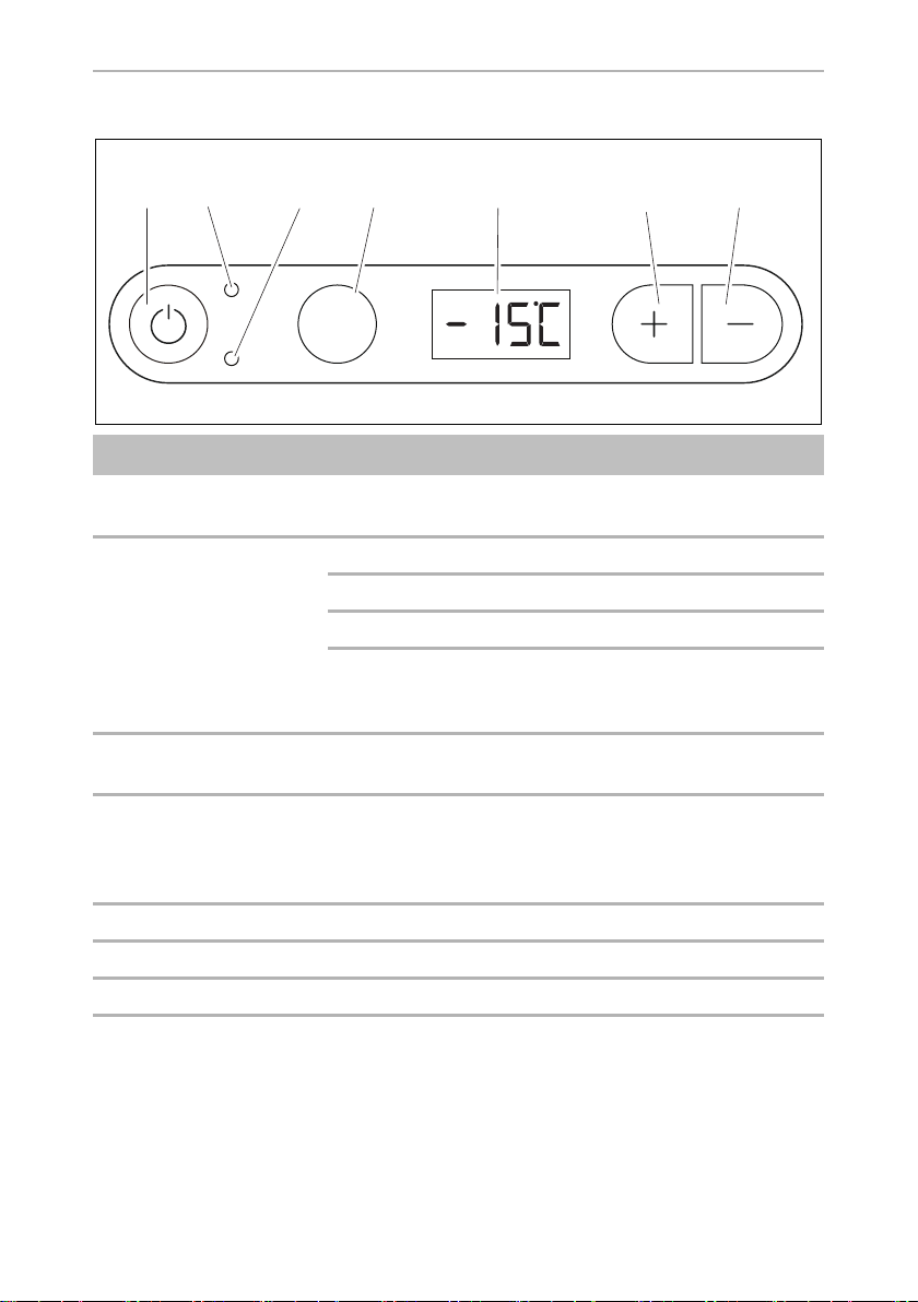
Operating panel
Item Description Explanation
1ON
OFF
Switches the cooler on or off when the button is pressed for
between one and two seconds
2 POWER Status indication
LED lights up green: Compressor is on
LED lights up orange: Compressor is off
LED flashes orange: Display switched off
automatically due to low
battery voltage
3 ERROR LED flashes red: Device is switched on but not
ready for operation
4 SET Selects the input mode
– Temperature setting
– Celsius or Fahrenheit display
– Set battery monitor
5 – Display, shows the information
6 UP + Press once to increase the value
7 DOWN – Press once to decrease the value
ERROR
POWER
SET
1 2 3 4 5 76
3
XTM40-O-AUS.book Seite 10 Montag, 7. Januar 2019 2:30 14
Table of contents
Other XTM Refrigerator manuals


