XtreamAIR SU01-W30 Troubleshooting guide

www.XtremeAirUsa.com PAGE 1
IMPORTANT: READ AND SAVE THESE INSTRUCTIONS
FOR RESIDENTIAL & INDOOR USE ONLY
Pro-X Series: PX01-W30/36
PX02-W30/36
PX06-W30/36/42
PX15-W30/36/42
SP03-W30/36/42
Ultra Series: UL02-W30/36
SU01-W30/36
Deluxe Series: DL02-W30/36
DL03-W30/36
DL06-W30/36
INSTALLATION GUIDE & USER’S MANUAL
WALL MOUNT RANGE HOOD

PAGE 2
IMPORTANT NOTICE:The Important Safety Instructions and warnings in this manual are not meant to cover all possible problems and/or situations that can
occur upon installation of this unit. Use extreme caution when installing, maintaining or operating this or any other appliance. Contact the XtremeAir USA, LLC,
Customer Support Team at 1.714.554.9000 or email: support@XtremeAirUsa.com with any concerns or situations that you do not understand. The
manufacturer disclaims all liability for any damage or injury caused as a result of not following instructions for installation contained
in this manual.
To avoid the possibility of an explosion or fire, do not store or use combustible, flammable or explosive vapors and liquids (such as gasoline) inside or in the
vicinity of this or any other appliance. Keep all combustible items (such as aerosol cans) away from cook top burners, ovens and range hoods. Do not store
flammable or explosive materials in adjacent cabinets or surrounding areas.
Disclaimer
:The manufacturer and/or distributor/reseller decline all responsibility in the event of failure to observe the instructions provided for installation,
maintenance and suitable use of the product. The manufacturer and/or distributor/reseller shall NOT be responsible for any injury due to negligence and the
warranty of the unit shall automatically be voided due to failure to observe proper safety and installation procedures. The manufacturer and/or
distributor/reseller will not be held responsible for any damages to personal property or real estate or any bodily injuries whether caused directly or indirectly
by the range hood.
WARNING -TO REDUCE THE RISK OF FIRE, ELECTRIC SHOCK, OR INJURY TO PERSONS, OBSERVE THE FOLLOWING:
*Use this unit only in the manner intended by the manufacturer. If you have questions, contact the manufacturer.
PRODUCT: Do not remove permanently affixed labels, warnings or plates from the product. This may void the warranty. Do not try to alter the hood.
INSTALLATION:The installation in this manual is intended for qualified installers, service technicians or persons with a similar qualified background. Installation
and electrical wiring must be provided by qualified professionals and in accordance with all applicable codes and standards, including fire-related construction.
When cutting or drilling into the wall or ceiling; do not damage electrical wiring and other utilities. It is recommended that two or more people assist with the
installation. The range hood may have very sharp edges; please wear protective gloves if it is necessary to remove any parts for installing, cleaning or
servicing.
VENTING: For kitchen range or cook top ventilating use only. DO NOT use units to exhaust hazardous or explosive materials and vapors. Ducted fans MUST
always be vented to the outdoors. DO NOT vent exhaust into spaces between walls, crawl spaces, ceiling, attics and/or garages. Use only metal ductwork. Old
duct work should be cleaned or replaced if necessary to avoid the possibility grease fires. Check all joints on ductwork to insure proper connections. All joints
should be properly taped.
ELECTRICAL: All electrical wiring must be properly installed, insulated and grounded. TURN POWER OFF and un-plug cords from outlet before servicing and/
or cleaning to insure your safety.
OPERATION: Caution is suggested when using high settings on cooking range. Keep all fan, baffle, spaces, filter, grease tunnel, oil container and grease-
laden surfaces clean. Grease should not be allowed to accumulate on fan, baffle, spaces, filter, grease tunnel, and oil container. Never allow the filters to
become blocked or clogged. Do not allow foreign objects such as cigarettes and/or napkins, to be absorbed into the hood. Clean ventilating fans frequently.
Grease should not be allowed to accumulate on the fan or filters.
DANGER
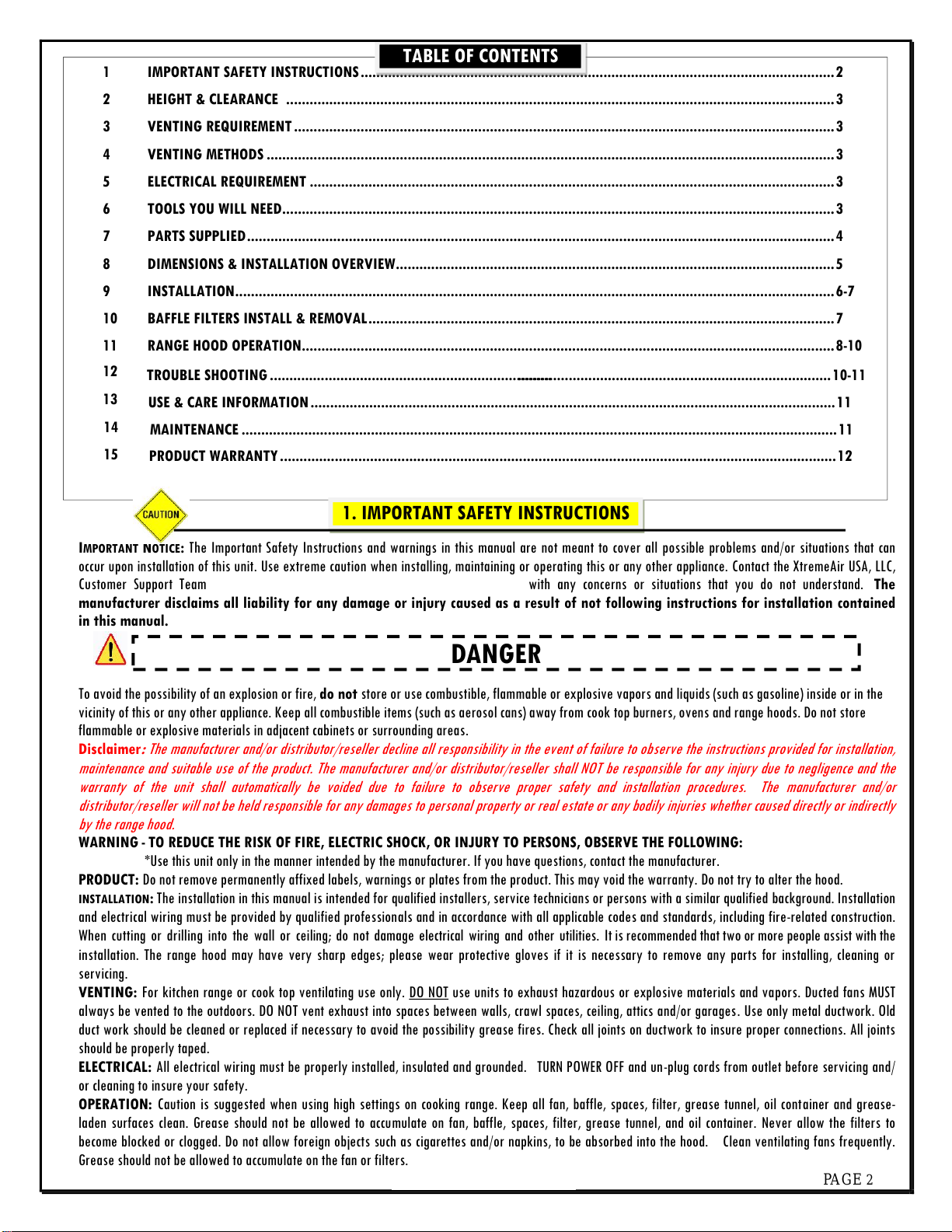
1 IMPORTANT SAFETY INSTRUCTIONS.........................................................................................................................2
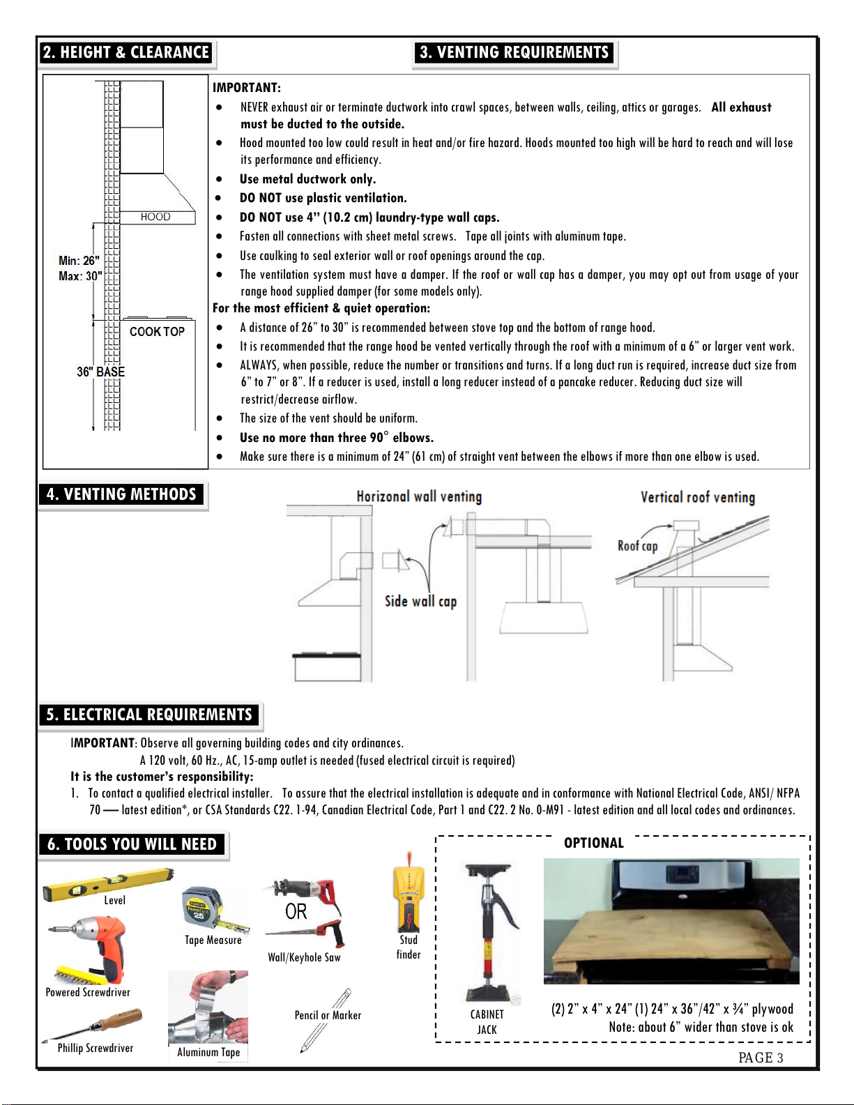
2 HEIGHT & CLEARANCE ............................................................................................................................................3
3 VENTING REQUIREMENT ..........................................................................................................................................3
4 VENTING METHODS .................................................................................................................................................3
5 ELECTRICAL REQUIREMENT ......................................................................................................................................3
6 TOOLS YOU WILL NEED.............................................................................................................................................3
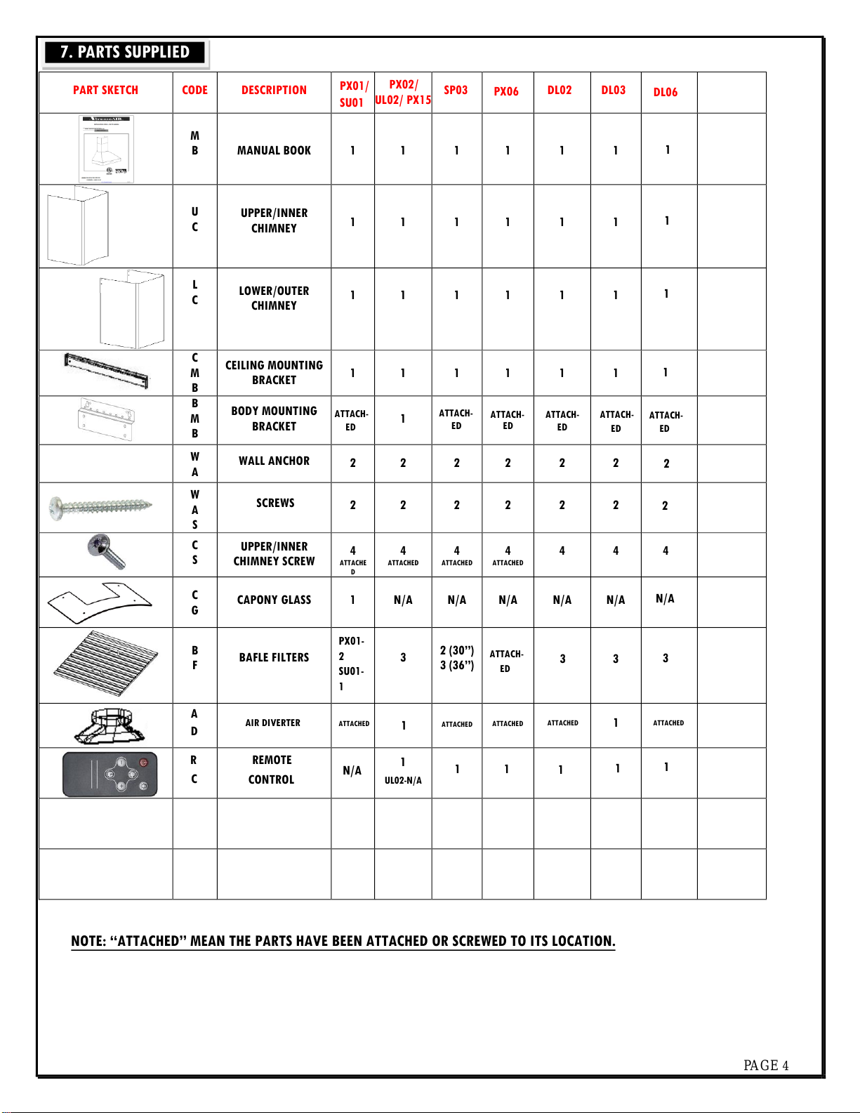
7 PARTS SUPPLIED......................................................................................................................................................4
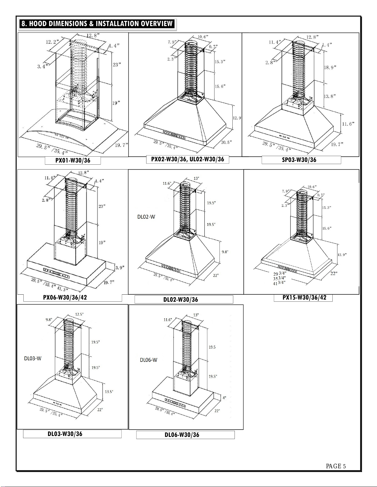
8 DIMENSIONS & INSTALLATION OVERVIEW................................................................................................................5
9 INSTALLATION.........................................................................................................................................................6-7
10 BAFFLE FILTERS INSTALL & REMOVAL.......................................................................................................................7
11 RANGE HOOD OPERATION........................................................................................................................................8-10
12TROUBLE SHOOTING ........................................................................................................................................................10-11
13
USE & CARE INFORMATION......................................................................................................................................11
14MAINTENANCE ........................................................................................................................................................11
15PRODUCT WARRANTY..............................................................................................................................................12
TABLE OF CONTENTS
1. IMPORTANT SAFETY INSTRUCTIONS

www.XtremeAirUsa.com PAGE 3
IMPORTANT: Observe all governing building codes and city ordinances.
A 120 volt, 60 Hz., AC, 15-amp outlet is needed (fused electrical circuit is required)
It is the customer’s responsibility:
1. To contact a qualified electrical installer. To assure that the electrical installation is adequate and in conformance with National Electrical Code, ANSI/ NFPA
70 —latest edition*, or CSA Standards C22. 1-94, Canadian Electrical Code, Part 1 and C22. 2 No. 0-M91 - latest edition and all local codes and ordinances.
2. HEIGHT & CLEARANCE
3. VENTING REQUIREMENTS
IMPORTANT:
NEVER exhaust air or terminate ductwork into crawl spaces, between walls, ceiling, attics or garages. All exhaust
must be ducted to the outside.
Hood mounted too low could result in heat and/or fire hazard. Hoods mounted too high will be hard to reach and will lose
its performance and efficiency.
Use metal ductwork only.
DO NOT use plastic ventilation.
DO NOT use 4” (10.2 cm) laundry-type wall caps.
Fasten all connections with sheet metal screws. Tape all joints with aluminum tape.
Use caulking to seal exterior wall or roof openings around the cap.
The ventilation system must have a damper. If the roof or wall cap has a damper, you may opt out from usage of your
range hood supplied damper (for some models only).
For the most efficient & quiet operation:
A distance of 26” to 30” is recommended between stove top and the bottom of range hood.
It is recommended that the range hood be vented vertically through the roof with a minimum of a 6” or larger vent work.
ALWAYS, when possible, reduce the number or transitions and turns. If a long duct run is required, increase duct size from
6” to 7” or 8”. If a reducer is used, install a long reducer instead of a pancake reducer. Reducing duct size will
restrict/decrease airflow.
The size of the vent should be uniform.
Use no more than three 90° elbows.
Make sure there is a minimum of 24” (61 cm) of straight vent between the elbows if more than one elbow is used.
4. VENTING METHODS
5. ELECTRICAL REQUIREMENTS
6. TOOLS YOU WILL NEED
Pencil or Marker
Phillip Screwdriver
Level
Aluminum Tape
Wall/Keyhole Saw
Tape Measure
Powered Screwdriver
CABINET
JACK
OPTIONAL
(2) 2” x 4” x 24” (1) 24” x 36”/42” x ¾” plywood
Note: about 6” wider than stove is ok
Stud
finder

www.XtremeAirUsa.com PAGE 4
PART SKETCH
CODE
DESCRIPTION
PX01/
SU01
PX02/
UL02/ PX15 SP03 DL02
M
B
MANUAL BOOK
1
1
1
1
1
1
U
C
UPPER/INNER
CHIMNEY
1
1
1
1
1
1
L
C
LOWER/OUTER
CHIMNEY
1
1
1
1
1
1
C
M
B
CEILING MOUNTING
BRACKET
1
1
1
1
1
1
B
M
B
BODY MOUNTING
BRACKET
1
ATTACH-
ED
ATTACH-
ED
ATTACH-
ED
W
A
WALL ANCHOR
2
2
2
2
2
2
W
A
S
SCREWS2 2 2 2 2 2
C
S
UPPER/INNER
CHIMNEY SCREW
4
ATTACHE
D
4
ATTACHED
4
ATTACHED
4
ATTACHED
4
4
C
G
CAPONY GLASS
1
N/A
N/A
N/A
N/A
N/A
B
F
BAFLE FILTERS
PX01-
2
SU01-
1
3
2 (30”)
3 (36”)
A
D
AIR DIVERTER 11
R
C
REMOTE
CONTROL N/A 1
UL02-N/A
11
NOTE: “ATTACHED” MEAN THE PARTS HAVE BEEN ATTACHED OR SCREWED TO ITS LOCATION.
7. PARTS SUPPLIED
PX06 DL03DL06
1
1
1
ATTACHED
1
ATTACH-
ED
2
2
4
N/A
3 3 3
ATTACH-
ED
1
ATTACHED ATTACHED
1 1
ATTACH-
ED
ATTACH-
ED
ATTACHED ATTACHED

www.XtremeAirUsa.com PAGE 5
8. HOOD DIMENSIONS & INSTALLATION OVERVIEW
PX06-W30/36/42 PX15-W//
PX02-W30/36, UL02-W30/36
P/
PX01-W30/36
DL02-W/
DL03-W/ DL06-W/

PAGE 6
\
9. INSTALLATION
STEP 3: PREPARE DUCTWORK & SINGLE OUTLET (SKIP THIS STEP IF DUCTWORK
ALREADY PRESENT)
A. Have 15amp, 120V, 60Hz, single outlet anywhere inside the chimney width lines (make
sure at least 2 inches below ceiling line for ceiling bracket mount).
B. Have 6 or 8 inch diameter ductwork (depending on your model requirements) brought
down from the ceiling to about the mark of mounting screws. (1-2 inches away from wall
is recommended since you need room to plug in the unit).
STEP 4: INSTALL CEILING BRACKET, MOUNTING ANCHORS & SCREWS
A. Place center of ceiling mount bracket in line with center line and a little of the way
down from the ceiling (line up holes with upper chimney before installing to confirm exact
distance). Once in place, secure with screws.
B. Pre-drill holes (1/8”) where your mounting marks are.
C. Slowly tighten wall anchors (2 total) until it is flush with the wall surface.
D. Insert mounting screws inside the wall anchors then slowly tighten it down. Make sure
to
leave about 1/8” space away from the wall to the inside screw’s head.
STEP 5: HANG THE HOOD & CONNECTION
A. Carefully lift and hang the hood body on the wall, attaching it
to 2 mounting screws already in place.
B. Level the hood body by using horizontal level
C. Use hand screw driver to tighten those 2 mounting screws
D. Connect the exhaust on the hood to the ductwork above.
E. Use aluminum tape to make all joints secure and all tight
F. Find the three pronged plug and connect to an electrical outlet
CAUTION: Do not release the hood until you finish step 6 below.
STEP 2: MARKING ON THE WALL
A. Center: is the center of cook top or stove.
B. Chimney width: is the width of the chimney (Varies with each model).
C. Mounting screws: where the hood body will be positioned from.
FOR PX01, PX/UL02/15 MODELS: please assemble body mounting bracket (BMB)
to the back of hood body first, so you can find
exact placement location. To do so, remove 6
screws located on the back of the hood and
place the bracket onto the hood with the
same 6 screws.
**MOUNTING SCREW HOLE DIMENSIONS:
WIDTH:
dimension from center to center of mounting bracket hole.
HEIGHT:
dimension from cook top to bottom of range hood (varies from 26” to
30”) plus from bottom of range hood to mounting bracket hole.
STEP 1: (OPTIONAL ONLY) PROTECT THE COOK TOP & CREATE WORK STATION
Have 2 pieces 2” x 4” x 20” on both sides of stove & plywood on top of them to protect cook
top or stove from damage or debris. This plywood will also create a comfortable work station
for easy installation of hood unit.
PX/ PX15
1

PAGE 7
STEP 7: INSTALLING CHIMNEYS - DO NOT REMOVE INNER CHIMNEY PROTECTIVE FILM UNTIL FINISHED INSTALLATION
1
OIL TUNNEL: Drop oil tunnel into recess
support near rear of hood.
Note: PX04 & PX06- skip this step
STEP 6: SECURE THE HOOD BODY & TEST RUN
A. Use a stud finder to find all studs below the hood body. Put blue tape on every stud
found.
B. Use 1/8” drill bit to drill though the back of hood in line with blue tape.
C. Secure the hood body by using the 2.0 inches wood screws (provided) through the
back of hood to the stud.
D. Refer to page 8, Range Hood Operation. Try a few test runs to ensure machine is
running properly.
STEP 6A: FOR PX01 & SU01 MODEL ONLY –INSTALL GLASS CANOPY
A. Loosen the four canopy screws and washers from the hood top.
B. Carefully place the canopy glass on the hood top then slightly tighten the four
canopy screws along with washers. DO NOT put excessive pressure against the
glass.
10. BAFLE FILTERS INSTALL & REMOVA
IMPORTAN:FOR THOSE MODELS THAT HAVE MORE THAN 2 BAFFLE FILTERS, ALWAYS INSTALL THE MIDDLE FILTER LAST WHEREAS REMOVE IT FIRST IF YOU ARE TRYING
TO REMOVE ALL OTHER FILTERS.
Angle baffle filter
toward back of
hood
2. Lift a baffle filter up above horizontal level
then slide forward into slot behind the front of
hood. To remove, please reverse the process
Install & Remove Baffle Filters
A. Remove outter chimney
protective film (not the
inner chimney).
B. Place both chimneys on
top of range hood base.
C. Secure outside chimney
to the base of the hood
(PX02/ UL02/ PX15
ONLY).
A. Lift up and attach the
innner chimney to the
ceiling mounting
bracket.
B. Screw the chimney into
place on both sides.
C. Remove inner chimney
protective film.


PAGE 9
F. Remote Control Sensor:
1. Remote control sensor receives infrared (IR) signal from the remote control. The maximum distance for IR data transmission is
10 feet and requires direct line of sight. The transmission distance may vary depending on temperature and remote control
battery condition.
2. Light settings are independent from other settings (including power-off delay) and lights have to be manually turned on or off.
3. The system saves user configurations, settings such as light, timer and blower (motor) speed will remain the same the next time it
is turned on.
2.FOR ALL ULTRA SERIES: TYPE 3: MECHANICAL BUTTON CONTROL
A. Activating Blower Function:
Press your designed speed (1,2,3)
B. Turn off power:
While the blower (motor) is running, press button (0) to turn off the motors.
C. To turn the light ON/OFF
While the light is off, press button (4) once to turn on the light.
Press button (4) again to turn the light off

www.XtremeAirUsa.com PAGE 10
1. If the range hood or lights does not operate after installation:
Check if the range hood has been plugged in. Make sure that all power has been turned back ON.
Swap out light assembly to working ones to deter mine whether it is caused by defective bulbs.
2. The range hood vibrates when the blower is on:
The range hood might not have been secured properly to the cabinet or wall.
Check if the blower wheel is damaged.
12.TROUBLESHOOTING
A.Make sure the range hood is unplugged or turn OFF breaker.
B.Pop out the light by pressing behind the light fixture.
C.Install new light bulb.
D.Put the light set back by pressing it in.
E.Plug in and range hood to test for operation.
3. The blower or fan seems weak:
Check that the duct sized used is at least 6”. Range hood WILL NOT function efficiently with insufficient duct size & loosely secured.
Check if duct is clogged or if damper unit (half-circular flapper) is not installed correctly or opening properly. A tight mesh on a side wall cap unit might
also cause restriction to the air flow.
4. The lights work but the blower is not spinning at all, is stuck or is rattling.
The blower might be jammed or scraping the bottom due to shipping damage. Please contact us immediately.
5. The hood is not venting out properly:
Make sure the distance between the stove top and the bottom of the hood is within 26” and 30” in distance.
Reduce the number of elbows and length of ductwork. Check if all joints are properly connected, sealed, and taped.
Make sure the power is on high speed for heavy cooking.
6. The hood is noisier than normal
The damper was not opened.
The duct is not secure and causes vibration.
The smaller duct size than required is being used.
7. Control panel is not active
Check to make sure the auto function is not on.

www.XtremeAirUsa.com PAGE 11
Operations:
Read and understand all instructions and warnings in this manual before operating the appliance. Save these instructions for future reference.
Always leave safety grills and filters in place. Without these components, operating blowers could catch on to hair, fingers and loose clothing.
NEVER dispose cigarette ashes, ignitable substances, or any foreign objects into blowers.
NEVER leave cooking unattended. When frying, oil in the pan can easily overheat and catch fire. The risk of self combustion is higher when the oil has
been used several times.
NEVER cook on “open” flames under the range hood. Check deep-fryers during use: Superheated oil may be flammable.
Cleaning:
The saturation of greasy residue in the blower and filters may cause increased flammability. Keep unit clean and free of grease and residue build-
up at all times to prevent possible fires.
FILTERS MUST BE CLEANED PERIODICALLY AND FREE FROM ACCUMULATION OF COOKING RESIDUE.
DO NOT operate blowers when filters are removed. Never disassemble parts to clean without proper instructions. Disassembly is recommended
to be performed by qualified personnel only. Read and understand all instructions and warnings in this manual before proceeding.
SAFETY WARNING: Never put your hand into area housing the fan while the fan is operating! For optimal operation, clean range hood and all baffle/spacer
/filter/grease tunnel/oil container regularly. Regular care will help preserve the appearance of the range hood.
Cleaning Exterior surfaces:
Clean periodically with stainless steel cleaner or hot soapy water and clean cotton cloth. Do not use corrosive or abrasive detergent (e.g.
Comet Power Scrub®, EZ-Off® oven cleaner), or steel wool/scoring pads, which will scratch and damage the stainless steel
surface. For heavier soil use liquid degrease such as “Formula 409®” or “Fantastic®” brand cleaner.
If hood looks splotchy (stainless steel hood), use a stainless steel cleaner to clean the surface of the hood. Avoid getting cleaning solution on or into
the control panel. Follow directions of the stainless steel cleaner. CAUTION: Do not leave on too long as this may cause damage to hood finish. Use
soft towel to wipe off the cleaning solution, gently rub off any stubborn spots. Use dry soft towel to dry the hood.
After cleaning, you may use non abrasive stainless steel polish such as 3M ® or ZEP®, to polish and buff out the stainless luster and grain. Always
scrub lightly, with clean cotton cloth, and with the grain.
DO NOT allow deposits to accumulate or remain on the hood.
DO NOT use ordinary steel wool or steel brushes. Small bits of steel may adhere to the surface and cause rusting.
DO NOT allow salt solutions, disinfectants, bleaches, or cleaning compounds to remain in contact with stainless steel for extended periods. Many of
these compounds contain chemicals, which may be harmful. Rinse with water after exposure and wipe dry with a clean cloth.
Cleaning Grease Filter / Stainless Steel Filter less Grill:
IMPORTANT: Drain oil from oil containers before oil and residue overflow!
The metal filters fitted by the factory are intended to filter out residue and grease from cooking. It needs not be replaced on a regular basis but are
required to be kept clean.
Filters should be cleaned after every 30 hours of use. Remove and clean by hand or dishwasher. Use proper degreasing detergent for stainless steel
and leave to soak if heavily soiled. Dry filters and re-install before using hood.
13.USE & CARE INFORMATION
14.MAINTENANCE

XtremeAIR USA HOOD TEN (10) YEARS MOTOR LIMITED WARRANTY
XtremeAIR USA Range Hood (hereunder called “The Company”) warrants its product against defects inmaterial or
workmanship for the time periods andas set forth below. **Note: for products purchased after January 2021**
Parts: For a period of one (1) year from the original date of purchase of product (“Parts Warranty”), The Company
will supply new orequivalent replacement parts inexchange for parts determined tobe defective. Themotor
warranty isextended for an additional nine (9)years toaccumulate ten (10) years total (motor only).
Labor: For a period ofone (1) year from the original date of purchase of the product (“Labor Warranty”), ifthe
product isdetermined to be defective, The Company will repair orreplace the product, at its option, at nocharge.
The Company will only cover labor performed at its facility. This warranty doesnot cover on site labor costs. After
the Labor Warranty period, labor charges are applicable.
Warranty Performance: In the event ofany malfunction ordefect covered under the terms ofthis warranty,
immediately contact the company. Written notice of any malfunction ordefect must be given within 7 days ofthe
time of discovery ofthe malfunction and must be accompanied bythe original consumer purchase receipt which
shows the date of purchase.
To obtain warranty service, the products must be delivered, freight prepaid, ineither its original packaging or
packaging affording an equal degree ofprotection tothe company authorized service facility as specified below. The
repaired unit will be returned at The Company’s expense.
16142 Harbor Blvd., Fountain Valley, CA92708, USA
For specific instructions onhow to obtain warranty service for your product, contact XtremeAir USA byemailing
Repair/ Replacement Warranty: This Limited Warranty shall apply toanyrepair, replacement part orreplacement
product for the remainder of the original Limited Warranty period. Any part or product replaced under this Limited
Warranty will become the property ofThe Company.
This Limited Warranty only covers product issues caused bydefects inmaterial orworkmanship during ordinary
consumer use and isnon-transferable. Itdoes notcover product issues caused byany other reason, including but not
limited to: product issues due to commercial use, actsofGod, misuse, defects resulting from damages sustained
during shipping, unauthorized repair, modification of or to any part of the XtremeAir product.
This Limited Warranty doesnot cover XtremeAir products sold AS ISor WITH ALL FAULTS, light bulbs, remote
control, normal maintenance and service, costs ofremoval orinstallation. This Limited Warranty is invalid if the
factory-applied serial number has been altered orremoved from the product.
DISCLAIMERS
XtremeAir USA shall not be responsible for loss of use or other incidental consequential costs, expenses or
damages which may occur. Under nocircumstances shall XtremeAir USA oranyofits representatives be held liable
for injury toany person or damage toany property, however arising. This warranty gives you specific legal rights,
and you may have other rights whichvary from state to state.
All rights reserved
This manual suits for next models
25
Table of contents
Other XtreamAIR Ventilation Hood manuals
Popular Ventilation Hood manuals by other brands

Caple
Caple BUCH instruction manual

CookMax
CookMax BCS1130ILL Operating instruction

Greenheck
Greenheck Exhaust Fan SMD-302M installation instructions

Inalto
Inalto ARC60BS user manual

Whirlpool
Whirlpool AT201 installation manual

CNA Group
CNA Group CATA & Can Roca GRECO Installation, use and maintenance instructions

Hotpoint
Hotpoint PHBG 9.8 LTSI X Instructions for use

Miele
Miele DA 362-75 Operating and installation instructions

Whirlpool
Whirlpool RJH 3330-1 Installation and operating instructions

AEG
AEG DPB5650M user manual

Elba
Elba MARS-V2-90 IS-X Installation guide & operation manual

Faber hoods
Faber hoods In-nova premium user manual