Xtreme Power 75159 Original instruction manual

13” TIMER SAND FILTER PLUS 3/4HP ABOVEGROUND SELF
PRIMING POOL PUMP
SAVE THIS MANUAL: KEEP THIS MANUAL FOR SAFETY WARNINGS, PRECAUTIONS, ASSEMBLY,
OPERATING, INSPECTION, MAINTENANCE AND CLEANING PROCEDURES. WRITE THE PRODUCT’S
SERIAL NUMBER ON THE BACK OF THE MANUAL NEAR THE ASSEMBLY DIAGRAM (OR MONTH
AND YEAR OF PURCHASE IF PRODUCT HAS NO NUMBER).
OWNER’S MANUAL AND SAFETY INSTRUCTIONS
ITEM: 75159
FOR QUESTIONS PLEASE CALL OUR CUSTOMER SUPPORT: (909) 628 0880 MON-FRI 9AM TO 3PM PST

IMPORTANT SAFETY INFORMATION
GENERAL SAFETY WARNINGS
SERIOUS BODILY INJURY OR DEATH CAN RESULT IF THIS PUMP AND SAND FILTER IS NOT
INSTALLED AND USED CORRECTLY. INSTALLERS, POOL OPERATORS AND POOL OWNERS
MUST READ THESE WARNINGS AND ALL INSTRUCTIONS BEFORE USING THIS PUMP AND
SAND FILTER.
SAFETY
Most states and local codes regulate the construction, installation, and operation of public pools and
spas, and the construction of residential pools and spas. It is important to comply with these codes,
many of which directly regulate the installation and use of this product. Consult your local building and
health codes for more information.
IMPORTANT: Attention Installer: This Installation and User’s Guide contains important
information about the installation, operation and safe use of this pump and sand lter. This
Guide should be given to the owner and/or operator of this equipment.
The sand lters are designed to work with water temperature > 0° C and < than 45 0° C. The lter
should never be operated outside of these temperatures or damage may occur. The installation should
be carried out in accordance to the safety instructions of swimming pools and the specic instructions
for each facility.
A pool or spa pump must be installed by a qualied pool and spa service professional in accordance
with the National Electrical Code and all applicable local codes and ordinances. Improper installation
may create an electrical hazard which could result in death or serious injury to pool users, installers, or
others due to electrical shock, and may also cause damage to property
To reduce the risk of injury, do not permit children to use or operate this pump and sand lter.
Do not bury the electrical cord. Locate the cord where it will not be damaged by lawn mowers, hedge
trimmers and other equipment.
To reduce the risk of electric shock, replace damaged cord immediately. Use a qualied electrician to
replace the cord.
When setting up pool water turnovers or ow rates the operator must consider local codes governing
turnover as well as disinfectant feed ratios
To reduce the risk of electric shock, do not use extension cords, timers, plug adaptors or converter
plugs to connect unit to electric supply; provide a properly located outlet.
Pumps improperly sized or installed or used in applications other than for which the pump was intended
can result in serious personal injury or death. These risks may include but not be limited to electric
shock, re, ooding, suction entrapment or serious injury or property damage caused by a structural
failure of the pump or other system component
NEVER run the pump when dry. Doing so will damage the seals, causing leakage and ooding. Make
sure to ll the pump with water before starting the motor.
NEVER put chemicals directly into the suction inlet. Doing so can damage the product and void your
warranty.
Position this product away from pool, so as to prevent children from climbing on it and access the pool.
1

IMPORTANT SAFETY INFORMATION
Do not operate this product when pool is occupied.
To reduce the risk of entrapment hazard, never enter the pool if suction strainer component is loose,
broken, cracked, damaged or missing. Replace loose, broken, damaged, cracked or missing suction
strainer components immediately.
Never play or swim near suction ttings. Your body or hair may be trapped causing permanent injury or
drowning.
To prevent equipment damage and risk of injury, always turn pump off before changing the lter control
valve position.
Never operate this product above the maximum working pressure stated on the lter tank.
Hazardous Pressure. Improper tank valve cover assembly could cause the valve cover to blow off and
cause serious injury, property damage or death.
This product is for use with storable pools only. Do not use with permanently-installed pools. A
storable pool is constructed so that it is capable of being readily disassembled for storage and
reassembled to its original integrity. A permanently-installed pool is constructed in or on the
ground or in a building such that it cannot be readily disassembled for storage.
The suction and relief valve must be opened before starting the circulating system of the pump. Doing
so may result in injury or property damage.
WARNING! Electric Shock Hazard: MAKE SURE to shut off the power supply before draining the
pump.
If water leakage happens, remove the connector and clean the raw materials such as belts and reinstall
the connector.
HIGH PRESSURE FROM THE SAND FILTER CAN CAUSE SEVERE INJURY OR MAJOR PROPERTY
DAMAGE DUE TO TANK SEPARATION. RELEASE ALL PRESSURE AND READ INSTRUCTIONS
BEFORE WORKING ON THE SAND FILTER. IF THE FILTER CLAMP ISADJUSTED UNDER PRESSURE,
THE TANK CAN SEPARATE, CAUSING SERIOUS INJURY OR MAJOR PROPERTY DAMAGE.
PUMPS REQUIRE HIGH VOLTAGE WHICH CAN SHOCK, BURN, OR CAUSE DEATH.
BEFORE WORKING ON PUMP! ALWAYS DISCONNECT POWER TO THE POOL PUMP AT THE
CIRCUIT BREAKER BEFORE SERVICING THE PUMP. FAILURE TO DO SO COULD
RESULT IN DEATH OR SERIOUS INJURY TO SERVICE PERSON, POOL USERS OR OTHERS DUE
TO ELECTRIC SHOCK.
2

3
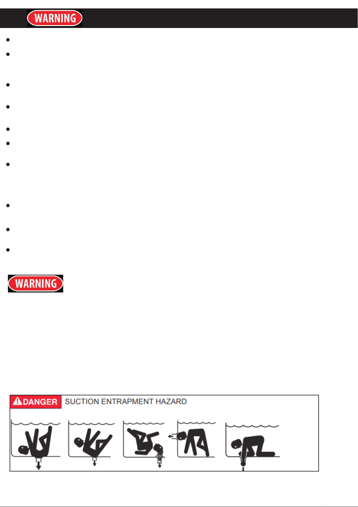
POOL AND SPA PUMPS MOVE LARGE VOLUMES OF WATER, WHICH CAN POSE EXTREME
DANGER IF A PERSON;S HAIR COMES IN PROXIMITY TO A DRAIN THAT IS NOT THE PROPER
SIZE FOR THE PUMP OR PUMPS.
The Virginia Graeme Baker Pool and Spa Safety Act imposes certain new requirements on owners and
operators of swimming pools and spas. Pools or spas constructed on or after December 20, 2008, shall
utilize:
(A) No submerged suction outlets, a gravity drainage system with ASME/ANSI cover(s), one or more
unblock-able outlets; or
(B) A multiple main drain system without isolation capability with suction outlet covers that meet ASME/
ANSI A112.19.8 Suction Fittings for Use in Swimming Pools, Wading Pools, Spas, and Hot Tubs and
either:
(I) A safety vacuum release system (SVRS) meeting ASME/ANSI A112.19.17 Manufactured Safety Vacuum
Release Systems (SVRS) for Residential and Commercial Swimming Pool, Spa, Hot Tub, and Wading Pool
Suction Systems and/or ASTM F2387 Standard Specication for Manufactured Safety Vacuum Release
Systems (SVRS) for Swimming Pools, Spas and Hot Tubs or
(ii) A properly designed and tested suction-limiting vent system or
(iii) An automatic pump shut-off system. Pools and spas constructed prior to December 20, 2008, with a
single submerged suction outlet shall use a suction outlet cover that meets ASME/ANSI A112.19.8 and
either:
(A) A multiple main drain system without isolation capability, or
(B) A safety vacuum release system (SVRS) meeting ASME/ANSI A112.19.17 and/or ASTM F2387, or
(C) A properly designed and tested suction-limiting vent system, or
(D) An automatic pump shut-off system, or
(E) Disabled submerged outlets, or
(F) Suction outlets shall be recongured into return inlets.
This lter operates under high pressure. When any part of the circulating system (e.g., clamp, pump, lter,
valves, etc.) is serviced, air can enter the system and become pressurized. Pressurized air can cause the
lid or control valve to separate which may result in serious injury, death, or property damage. To avoid this
potential hazard, follow these instructions.
1. Before repositioning valves and before beginning the assembly,
disassembly, or adjustment of the clamp or any other service of the circulating system:
(a) Turn the pump off and shut off any automatic controls to ensure the system is not inadvertently started
during the servicing;
(b) Open manual air relief valve;
(c) Wait until all pressure is relieved, pressure gauge must read zero (0).
2. Whenever installing the lter clamp, follow the lter valve and clamp installation instructions exactly.
3. Once service on the circulating system is complete, follow system restart instructions exactly.
4. Maintain circulation system properly. Replace worn or damaged parts immediately (e.g., clamp, pressure
gauge, relief valve, o-rings, etc.).
5. Be sure that the lter is properly mounted and positioned according to instructions provided.
Failure to operate your lter system or inadequate ltration can cause poor water clarity obstructing
visibility in your pool and can allow diving into or on top of obscured objects, which can cause serious
personal injury or drowning.
This lter operates under pressure. With the valve clamped properly and operated without air in the
system, this lter will operate in a safe manner. Air entering the lter and the valve not clamped
correctly can cause the valve to separate, which could cause serious personal injury and/or property
damage.
IMPORTANT SAFETY INFORMATION

4
Always turn pump off before changing valve positions. Changing valve positions while the pump is running
can damage the control valve, which may cause serious injury or property damage.
Chemical fumes and/or spills can cause serious corrosion to the lter and pump structural components.
Structurally weakened components can cause lter, pump or valve attachments to separate and could
cause serious bodily injury or property damage. High voltage can cause serious or fatal injury. Always
install a suitable GFCI at the power source of this unit as an added safety precaution. Article 681-31 of the
NEC requires that a GFCI be used if this pump is used with a storable pool.
Never work on the pump while it is running or power is still connected. High voltage can cause
serious or fatal injury. A suitable ground fault interrupter should always be installed at the power
supply source of this unit. Be sure to ground the motor before connecting to electrical AC power
supply. Failure to ground the motor can cause serious or fatal electrical shock hazard. DO NOT
ground to a gas supply pipe line.
FOR CORD AND PLUG CONNECTED UNITS: Connect only to a ground type receptacle protected
by a Ground Fault Circuit Interrupter (GFCI). Contact a qualied electrician if you cannot verify
that the receptacle is protected by GFCI. Do Not Bury Cord. Locate cord to minimize abuse from
lawn mowers, hedge trimmers, and other equipment. To reduce the risk of electrical shock, replace
damaged cord immediately. To reduce the risk of electrical shock, Do Not Use an extension cord to
connect unit to electrical supply; provide a properly located outlet.
SAFETY / FEATURES
PRODUCT FEATURES
This sand lter is ideal for keeping pool cleaner and cleaner system easy to operate. It features top mount
multi-ports for making using the system and backwashing quick and easy. It also is powered by a 3/4 HP
with timer.
13” Sand Filter with 4-Way Valve
3/4HP Self-Priming Digital Timer Pump 2640 GPH
115V 60HZ 3.6AMP 3-Prong Plug with Electric Cable
Recommended for above-ground pools up to 10,000 gallons
Max Water Temperature 105 F
Max Suction 32ft
ETL certicated
UL Listed
CSA certicated

4
INSTALLATION
PUMP LOCATION AND MOUNTING:
• THE SYSTEM MUST BE INSTALLED ON A SOLID LEVEL AND VIBRATION-FREE BASE.
• PROVIDE A LOCATION PROTECTED FROM THE WEATHER, MOISTURE, FLOODING AND
FREEZING TEMPERATURE.
• PROVIDE ADEQUATE ACCESS, SPACE AND LIGHTING FOR ROUTINE MAINTENANCE.
• PUMP MOTOR REQUIRES FREE CIRCULATION OF AIR FOR COOLING. DO NOT INSTALL
THE PUMP IN A DAMP OR NON-VENTILATED LOCATION. A TEAM OF 2 OR MORE PEOPLE IS
RECOMMENDED FOR SETTING UP THIS PRODUCT.
MOTOR PRE-FILTERING ASSEMBLY SETUP:
1. REMOVE THE SAND FILTER AND ITS ACCESSORIES FROM THE PACKAGING CAREFULLY AND
INSPECT FOR ANY VISIBLE DAMAGE. IF PARTS ARE DAMAGED CONTACT YOUR LOCAL SERVICE
CENTER LISTED AT THE BACK OF THIS OWNER’S MANUAL.
2. IN A COUNTER-CLOCKWISE MOTION UNSCREW THE LEAF TRAP COVER (14) FROM THE PRE-
FILTER HOUSING. TAKE OUT THE BASKET (16) AND FILTER HOUSING NUT (17) (SEE DRAWING 10).
3. CONNECT THE PRE-FILTER HOUSING TO THE MOTOR WATER INLET. NOTE: ALIGN THE
CONNECTOR IN THE PRE-FILTER HOUSING WITH THE WATER INLET ON THE MOTOR.
This pump utilizes advanced technology with the feature of an automatic timing controller. In accordance
with the following simple yet effective preventative measures when installing the Sand Filter Pump.
1. Make sure to tighten the anchor bolts in order to avoid the inuence of vibrational movements.
2. The suction hose of the pump should be larger than 40mm and its diameter must be equal or larger than
the siameter of the release hose.
3. DO NOT allow any air to enter the pump while it is running.
4. The pump must be connected to the correct power supply and voltage. This can be found on the nameplate
label.
5. Connections should be made by a qualied technician.
6. The suction hose must be continuously tilted upwards from the bottom. The joint should be tight but not
too tight.
7. The ideal temperature for a working pump is 0 °C - 40 °C. If the temperature is too high or low, the pump
will stop working. Otherwise it may damage the lter and pump.
8. A ground lead must be used to protect the motor.
9. To avoid deforming the pump, the weight of the installed hoses should not be added to the pump.

5
1. Pump needs screw and cover to install on the lter drain.
2. Press and turn the sand tank to mount it to the sand lter support with correct direction, drain plug
on the outside (see below)
3. Insert the tube with diffuser body inside the tank as above picture shows, then place the funnel on
the tank’s mouth and out the quartz sand into the tank. A 12” sand lter requires about 19kg of sand to
ll the tank, a 14” sand ller needs about 27kg of sand to ll the tank.
4. Remove the funnel and make sure the tank’s neck is clean. Put the O-ring on the valve and use
clamp to x the valve with the tank. Pump port valve direction needs to face pump’s out-port.
INSTALLATION

INSTALLATION
6
5. Connect the sand tank to the pump with hose and hose adapters.
INSTALLATION NOTES:
Make sure the lter has worked under work pressure and using a pressure control valve when the
system is using a booster pump.
If the pump position is higher than the water level, it requires installing an isolation valve. It can stop
the water return back when doing the general inspection.
If the pump position is higher than the water level, it requires installation of the back water control
valve.
Reduce the connection adapters and hose connection, bending as little as possible. Decreasing the
water ow scrub can reach the maximum effectiveness
Ensure solvents are not excessively applied to the tting as this can run onto the O-ring and create
sealing issues.
Do not over tighten ttings or adapters.
HOW TO USE:
1. Inspect all connections have been made and are secure.
2. Depress the top mount valve handle and rotate to BACKWASH position.
3. Prime and start pump according to the pump instructions.
NOTE
All suction and discharge valves must be opened when starting the system. Failure to do so can
cause severe personal injury. Make sure the lter vessel are full. Fill the water before start-up the
pump. Failure to do so can cause damage to the pump.
4. Once water ows steadily out of the waste line, run the pump for at least 2 minutes. The initial back-
washing of the lter is recommended to remove any impurities of ne sand.
5. Turn the pump off and set the valve to RINSE position. Start the pump and operate until water in the
sight window is clear. Turn the pump off and set the valve to the FILTER position and restart the pump.
Your lter is now operating in the normal lter mode, ltering particles from the pool water.

7
INSTALLATION
POWER CONNECTION
Be sure to check whether used voltage is corresponding to the required voltage indicated on the
nameplate label. The voltage for the motor should not exceed 10% or below the requirement on the
requirement on the nameplate label. If too much voltage is applied, the motor will overheat and lead
to overload trip and shorten the life of the component. All connections must be applied by a qualied
technician. All wiring must comply with local and national and local laws. The leakage circuit breaker
must be congured to avoid electric shock when deterioration of the insulation occurs due to product
age.
CONTROL PANEL INSTRUCTION
TIMER INITIATION
NOTE: Make sure the power supply is off.
1. Unscrew the four screws on the lid of the terminal box and remove the lid.
2. Remove the battery.
3. Remove the rubber lm on the surface of the battery.
4. Replace the battery.
5. Replace the lid on the terminal box and re-tighten the four screws.
SWIMMING POOL AND SPA PUMP
MADE IN CHINA
MODEL : 72717
VOLTS : 115V
AMPS : 3.6A
QMAX : 150L/min (44GPM)
MAXIMUM WATER TEMPERATURE: 40 °C
MOTOR OVERHEATING PROTECTION DEVICE
Hz : 60
HMAX : 10M
TIMES
ON/OFF
2h 4h 6h 8h 10h 12h 16h 24h
TIMER
INDICATOR
ON/OFF
BUTTON
TIMER
BUTTON
SINGLE CYCLE
INDICATOR
BUTTON CONTROL INSTRUCTION

OPERATION
8
BUTTON INSTRUCTION
ON / OFF BUTTON: Starts and stops the pump
TIMER BUTTON: Set the desired operation period: 2h/4h/6h/8h/10h/16h/24h
Depressing the Timer button more than 10 seconds the Single Cycle indicator light will ash. If the Timer
Indicator light ashes in ‘24h’ this means the Single Cycle Indicator light did not work. Press the TIME
button to adjust the time. The pump must be stopped, otherwise the time cannot be adjusted. There are
two operation modes in the control panel: Continuous Mode and Single Cycle Mode
CONTINUOUS MODE:
After turning on the pump, the default setting is 24 hours continuous operation (Indicator light ashes in
24hr marker) To set the desired operation period press the TIMER button, the indicator lights ash among
2h/4h/6h/8h/10h/16h/24h. Then press the ON / OFF button, the pump should start running. The running
time is what the indicator light shows.
TIMES
ON/OFF
2h 4h 6h 8h 10h 12h 16h 24h
TIMES
ON/OFF
2h 4h 6h 8h 10h 12h 16h 24h
SINGLE CYCLE MODE:
Depressing the TIMER button more than 10 seconds the Single Cycle Indicator light will ash and switch
to Single Cycle mode. In the Single Cycle Mode press ON, the pump will work and Stop when it runs out
on the running time and will work again until the power supply is reconnected. To change the setting time,
press the Timer button.
For example, if you see the timer to 4h and press ON at 8:00, the pump will operate for 4 hours and stop at
12 and the indicator light will stop ashing. The pump will start again for 4 hours at 8:00 the following days.
For example, if you see the timer to 4h n a single cycle mode the pump will stop automatically after running
for 4 hours and it will not start again until you cut off the power and reconnect the power supply.

MAINTENANCE AND TROUBLESHOOTING
9
Conrm the screws in the baseboard are installed tightly. If any are found, re-tighten them before use.
Conrm the power cords are in good condition. If any parts are worn, cracked or in bad condition,
replace them prior to starting the pump.
The pump should be stopped immediately if the temperature is too high. Inspect and if need be, have
a technician repair it.
If loud noises are coming from the pump, turn the power off immediately and have a service technician
service and repair it.
TROUBLESHOOTING

8
THE MANUFACTURER AND/OR DISTRIBUTOR HAS PROVIDED THE PARTS LIST AND ASSEMBLY
DIAGRAM IN THIS MANUAL AS A REFERENCE TOOL ONLY. NEITHER THE MANUFACTURER OR
DISTRIBUTOR MAKES ANY REPRESENTATION OR WARRANTY OF ANY KIND TO THE BUYER THAT
HE OR SHE IS QUALIFIED TO MAKE ANY REPAIRS TO THE PRODUCT, OR THAT HE OR SHE IS
QUALIFIED TO REPLACE ANY PARTS OF THE PRODUCT. IN FACT, THE MANUFACTURER AND/OR
DISTRIBUTOR EXPRESSLY STATES THAT ALL REPAIRS AND PARTS REPLACEMENTS SHOULD BE
UNDERTAKEN BY CERTIFIED AND LICENSED TECHNICIANS, AND NOT BY THE BUYER. THE BUYER
ASSUMES ALL RISK AND LIABILITY ARISING OUT OF HIS OR HER REPAIRS TO THE ORIGINAL
PRODUCT OR REPLACEMENT PARTS THERETO, OR ARISING OUT OF HIS OR HER INSTALLATION
OF REPLACEMENT PARTS THERETO.
Record Product’s Serial Number Here:
Note: If product has no serial number, record month and year of purchase instead.
Note: Some parts are listed and shown for illustration purposes only and are not available individually
as replacement parts.
PLEASE READ THE FOLLOWING CAREFULLY
Table of contents
Popular Lighting Equipment manuals by other brands

Vision & Control
Vision & Control LDLF30x240-G525/24V/-a Instructions for use

Techly
Techly I-LED LUMES quick start guide

Lupine
Lupine Betty R Mounting instructions

Knightsbridge
Knightsbridge LWALL1A Installation & maintenance manual

LED2WORK
LED2WORK TUBELED-70 DC operating instructions

MG
MG PATLABOR IT40SA3 instruction manual

TIME LED
TIME LED 780688 Installation and operating instructions

Ayrton
Ayrton Mistral TC manual

CONIC
CONIC LB612FC user manual

involight
involight LEDPAR189 user manual

DOMUS LINE
DOMUS LINE MAGIC TUNE TW installation manual

Chauvet Professional
Chauvet Professional ROGUER1ESPOT Operating instructions & parts manual