Xtreme XTD88 User manual

User’s manual
DEFLECTOR LINE
User’s manual
INDICE DEI CONTENUTI
1. Generalità
2. Istruzioni per l’uso
3. Istruzioni di sicurezza
4. Impilato a pavimento o sospeso?
5. Guida allo Stacking
6. Subwoofers
7. Guida generale all’uso dei Subwoofers
8. Amplificazione
9. Connettori
10. Lunghezza dei cavi
11. Configurazione di sistema
INDICE DEI CONTENUTI
1. Generalità
2. Istruzioni per l’uso
3. Istruzioni di sicurezza
4. Impilato a pavimento o sospeso?
5. Guida allo Stacking
6. Subwoofers
7. Guida generale all’uso dei Subwoofers
8. Amplificazione
9. Connettori
10. Lunghezza dei cavi
11. Configurazione di sistema
1. SAFETY
It is imperative that electro-acoustic speakers are used in full compli-
ance with safety regulations. Professional electro-acoustic systems
are capable of producing high levels of sound pressure, and must
therefore be used with care. Loss of hearing is cumulative, and may
result after exposure for long periods at sound pressure levels above
90 dB. Never stand close to the electro-acoustic speakers working
at high volume. For ground positioning, always check that the base
is flat and stable. Do not pile speakers up too high in outdoor areas,
where the wind may cause the stack to become unstable. Suspend-
ed systems must be assembled by qualified and experienced staff
and professional riggers.
2. GENERAL INFORMATION
The Deflector Line consists of 12 models, (8 speakers + 4 sub-
woofers), including the self-powered version with internal DSP, 24
bit at 96 kHz.
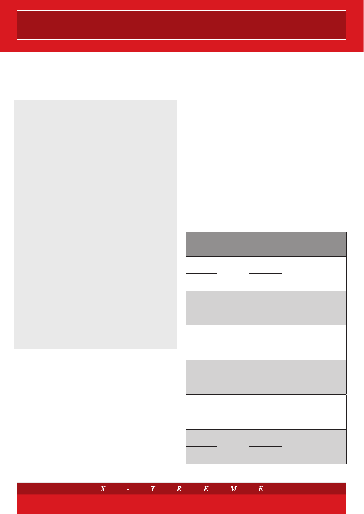
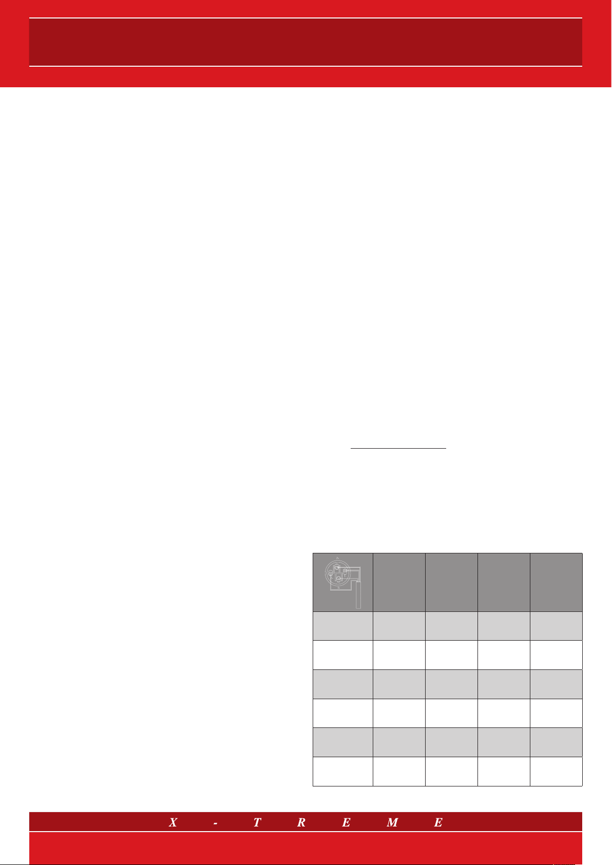
The table below summarizes the main features of each model.
Model LF
transducer
MF and HF
transducers
Passive
version
input config.
Active (/A)
version
amplifier
XTD88
2 X 8”
Neodimium
/
Full Range,
8 Ohm
Full Range
500 W
(@8Ohm)
Class D
XTD88/A 1 X 1”
Mylar
XTD12
1 X 12”
Neodimium
/
Full Range,
8 Ohm
Bi-amp
800+800 W
(@8Ohm)
Class D
XTD12/A 1 X 1.4”
Titanium
XTD15
1 X 15”
Neodimium
/
Full Range,
8 Ohm
Bi-amp
800+800 W
(@8Ohm)
Class D
XTD15/A 1 X 1.4”
Titanium
XTD1015
1 X 15”
Neodimium
1 X 10”
Neodimium Bi-amp,
8 Ohm
Bi-amp
800+800 W
(@8Ohm)
Class D
XTD1015/A 1 X 1.4”
Titanium
XTDS15
1 X 15”
Neodimium
/
8 Ohm /
16 Ohm
1600 W
(@16Ohm)
Class D
XTDS15/A /
XTDS18
1 X 18”
Neodimium
/
8 Ohm /
16 Ohm
1600 W
(@16Ohm)
Class D
XTDS18/A /
CONTENTS
1. Safety
2. General information
3. Controlled Air Flow Technology
4. Acoustic Wave Shaped HornTM
5. Subwoofers
6.
The Deflector product range & related transducers
7. System installation
7.1 Ground stacked or suspended installation?
7.2 Angulations
7.3 Rigging
8. Passive speakers: guidelines and precautions
8.1 Amplification and limitations
8.2 Presets
8.3 Connections between amplifiers and loudspeaker systems
8.4 Power cables
9. Guidelines for using active speakers
9.1 Technical information
9.2 Presets
10. System configurations
2/12
DEFLECTOR LINE
The most important features of this range can be outlined as follows:
1) a higher rigidity/weight ratio;
2) outstanding quality of the speakers and the electronics used in the
active versions.
Among many reasons why, Deflector Line features can be distin-
guished from those of competring products within the same sector
by the following characteristics:
• a cabinet made out of multuply Canadian birchwood with a thick-
ness of 15 mm,
• reinforced internal angles for the suspension system in 420ML al-
loy iron,
• pratical aluminium flying tracks on the upper and lower walls of the
speakers,
• ergonomic handles with a double grip,
• sound-transparent grid - it does not obstruct the holes in the internal
sponge - , secured to the chassis with retractable screws, that are
embedded in specific holes in the wood,
• a neodymium woofer with a 4” coil supported by fibreglass,
• an innovative AWSH™ (Acoustic Wave Shaped Horn),
• proprietary technology curved deflector.
3. CONTROLLED AIR FLOW TECHNOLOGY
All of the Deflector line upper modules (with the exception of the
“small” 2-way model XTD88) have been designed and produced
with an extremely innovative bass reflex. The classic tubular shape
has been superseded by a “sail-side” duct placed in the immediate
vicinity of the woofer, between it and the base of the cabinet, follow-
ing its circular profile. This solution was reached during the design
stage, relying on particular fluido-dynamic simulations, with the aim
of minimizing air turbulence inside the cabinet and the duct itself.
As well as being considered for different types of clusters based on
the horn’s dispersion angles, the mixed inclination of the outer walls
has also been optimized, taking into account the afore-mentioned
simulations, with a view to harmonizing the sound pressure inside the
cabinet and reducing resonance to the minimum.
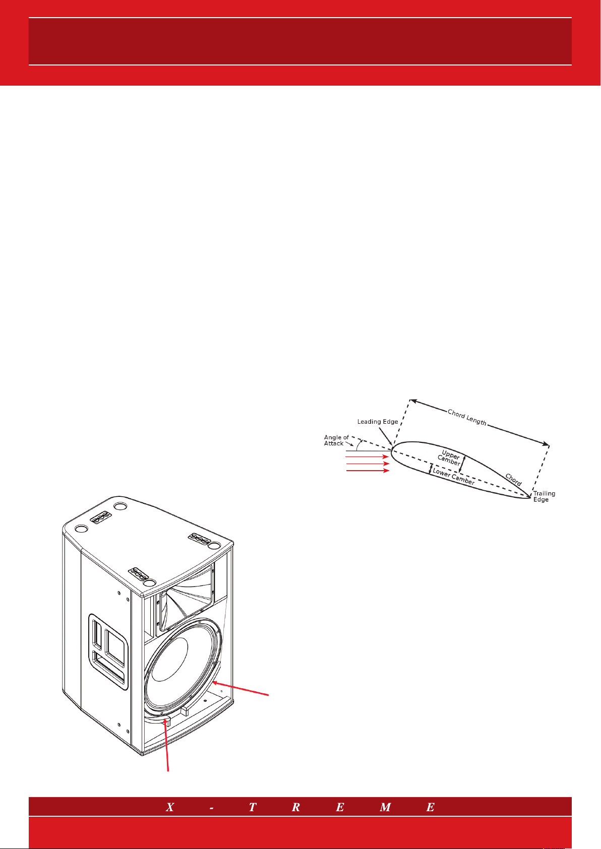
Fig. 1 Bass reflex with curved deflector
While standing in front of a speaker and sectioning it lengthwise with
a perpendicular plane, it is easy to identify the profile of the deflec-
tor, which has a convex-concave shape (according to the convec-
tion that mentions the intrados first, which is the lower surface, and
then the extrados, the upper surface) and also a camber – this is
defined as the distance between the wing chord and the mean line:
concerning the classic “roundedness” of the wing surface – this is
extremely reduced so as not to unnecessarily obstruct the air flow
controlled by the deflector. As above-mentioned, the X-Treme de-
sign team carried out special fluid dynamic simulations and created
numerous prototypes in laboratory; all of this had the aim of reaching
the long-awaited air flow control generated inside the cabinet and
the duct. From irregular and vortical, due to the “whirlpool” of the
bass reflex, this flow is transformed – in a non-viscous environment
and at sufficient distance from the walls – into a regular and laminar
one, thanks also to the intervention of a specific back frame, which
has a 5 cm thickness and to the 5 degrees tilt of the plane where
the loudspeaker is mounted. As well as being conceived for its dif-
ferent types of clusters in accordance with the horn’s dispersion an-
gles, this mixed tilting of the outer walls was designed to eliminate
typical turbulences, which particularly appear on the tuning tube:
this means that the waves reflecting on the woofer are minimized
and, owing to the precise cone-duct alignment (the tolerance field is
measured in mm), the resonance and phase cancellation in the input
and output points disappear completely, with resulting harmony and
sound pressure optimization inside the cabinet.
Fig. 2 Base definitions of Controlled Air Flow Technology
4. ACOUSTIC WAVE SHAPED HORNTM
The aluminium AWSHTM (Acoustic Wave Shaped Horn) was de-
signed and manufactured using CAE tools (Computer Aided Engi-
neering) to guarantee the sound centre and woofer alignment, while
keeping the planes containing the openings of the woofer cone and
the horn itself perfectly fitted together. The production process is car-
ried out via die casting, by pouring the melted alloy into a permanent
metallic mould or die, specifically designed for this original product
on the specifications of the X-Treme engineers. The pressured man-
ufacturing process allows the mould cavity to be filled very quickly
and the probable injection due to the reduction caused by solidifica-
tion to be compensated. This produces the following effects: per-
fect and total cavity filling and a fine crystalline structure of the part,
free of imperfections. In the XTD88 and XTD1015 models, thanks
to a special AWSHTM horn being fitted in the opposite concave of
the speaker, it is possible to rotate the whole medium-high section
(horn+driver+panel) by 90°, therefore making it possible to maintain
the same coverage at high frequencies, both when the speaker is in
position, standard, vertical and when it is mounted horizontally. By
simply unscrewing the 8 screws in the external squared flange, it can
be rotated without damaging the connection cables or compromis-
ing the other internal elements.
3/12
User’s manual
Fig. 3 Horizontal and vertical installation,
maintaining horn orientation
5. SUBWOOFERS
The new subwoofer models XTDS15 and XTDS18 with a pass-band
configuration have been designed both physically and acoustically to
reach their maximum efficiency – thus the developed energy peak –
around 90 Hz: for this reason, these subwoofers are very compact
and “fast” and are designed to achive a higher output/dimension ratio.
The crossed internal reinforcement cages make the 15”-thick multi-ply
Canadian birchwood cabinet more resistant to the most critical and
enduring strains. Each model can be easily stacked both with other
unit of the same model, to create vertical subwoofer clusters, and
with the associated satellite: the XTD12 model is coupled with the 15”
subwoofer and the XTD15 and XTD1015 modules with the 18” one.
6. THE DEFLECTOR PRODUCT RANGE
AND RELATED TRANSDUCERS
The XTD88 model, like the amplified version XTD88/A, has two 250
W (AES) 8” woofers, with a Neodymium magnet and a 50 W driver,
with a Mylar membrane, a 1.4” coil, throat diameter of 1”, with an
in-built 1” AWSHTM aluminium horn. The horn dispersion angle is on
average 90° horizontal by 40° vertical. The speaker can produce a
maximum SPL peak of 129.5 dB.
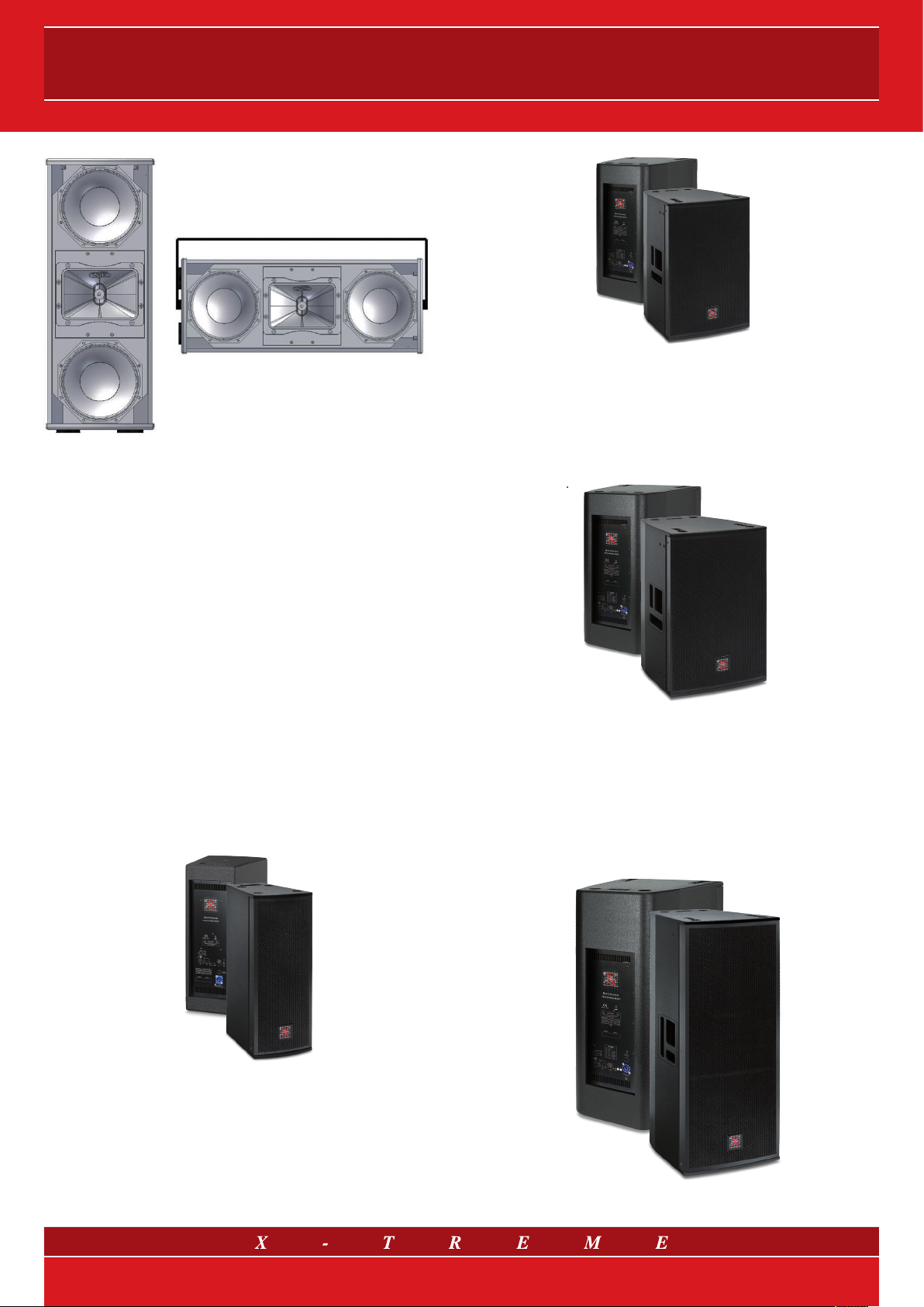
Fig. 4 XTD88 and XTD88/A models
The XTD12 model, like the amplified version XTD12/A, has a 700 W
(AES) 12” woofer with a Neodymium magnet and a 110 W driver with
a Polyimide-titanium membrane, a 3” coil, 1.4” throat diameter, and
an in-built 1.4” AWSHTM aluminium horn. The horn dispersion angle
horn is on average 90° horizontal by 50° vertical. The speaker can
produce a maximum SPL peak of 133 dB.
Fig. 5 XTD12 and XTD12/A models
The XTD15 model, like the amplified version XTD15/A, has a 600
W (AES) 15” woofer, a higher efficiency than the 12” XTD12, with a
Neodymium magnet and a 110 W driver with a Polyimide-titanium
membrane, a 3” coil, 1.4” throat diameter, and an in-built 1.4” AW-
SHTM aluminium horn. The horn dispersion angle is on average 90°
horizontal by 50° vertical. The speaker can produce a maximum SPL
peak of 134 dB.
Fig. 6 XTD15 and XTD15/A models
The XTD1015 model, like the amplified version XTD1015/A, has a
1000 W (AES) 15” woofer with a Neodymium magnet for low fre-
quencies; a 250 W (AES) 10” woofer with a Neodymium magnet
for medium frequencies; a 110 W driver with Polyimide-titanium
membrane, a 3” coil, 1.4” throat diameter, and an in-built 1.4” AW-
SHTM aluminium horn. The horn dispersion angle is on average 90°
horizontal by 50° vertical. The speaker can produce a maximum SPL
peak of 138 dB.
Fig. 7 XTD1015 and XTD1015/A models
4/12
DEFLECTOR LINE
The XTDS15 and XTDS18 subwoofers and their corresponding ampli-
fied versions both contain a woofer with a 15” Neodymium magnet at
1000 W (AES) for the XTDS15, and 18” 1200 W (AES) for the XTDS18.
The maximum SPL peaks are respectively 134 dB and 136 dB.
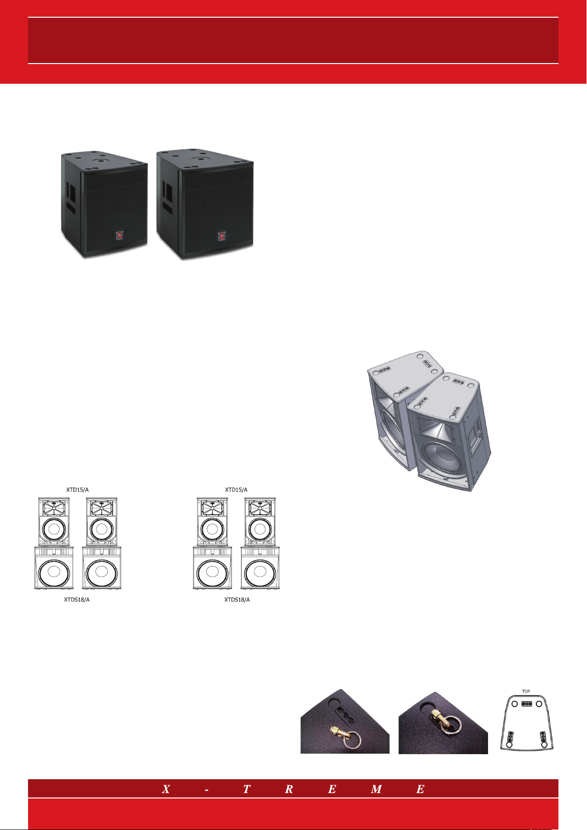
Fig. 8 XTDS15 and XTDS18 subwoofers
7. SYSTEM INSTALLATION
7.1 Ground stacked or suspended installation?
There are some arguments in favour of ground installation and some
which favour suspended; in both cases there are predominant rea-
sons for using one or the other, depending on practicality.
Excluding the possible logistical or visual problems of ground instal-
lation, which must be evaluated in each individual case, the positive
aspects of ground installation (stacking) are especially associated
with the main general coupling of low frequencies with the ground;
this makes the low part of the sound spectrum more efficient and, in
addition, it gains efficiency and response speed to the low transients.
This is also thanks to the fact that the speaker cabinets, which are
generally more physically constrained than the suspended ones, are
more stable and steady, and avoid turning part of the sound energy
into structure movement and losing it as a consequence. Another
point in favour of ground installation from the “spatial” and “psychoa-
coustic” perspectives, is the fact that the sound physically comes
from the points close to the stage, and therefore to the music scene.
Fig. 9 Stack installation of Deflector speakers
The choice of speaker suspension (flying), however, becomes com-
pulsory in all of those cases in which ground installation does not
provide the required sound coverage. When the medium-high fre-
quency transducers are not high enough compared to the listeners’
head-level, high frequencies will be poorer even at short distances,
due to the sound’s action of “friction” on the public (this being a
sound insulation element) and sound refraction phenomena, owing
to the vertical thermal gradient created by the public themselves.
Therefore, in general, ground installation is of little use to long dis-
tance coverage (the problem is reduced in the case of tilted slabs,
in which far away listeners find themselves at a slightly higher level
compared to those in the first few rows).
Additionally, for long distance coverage, guaranteeing sufficient SPL
(Sound Pressure Level) in the last few rows can lead to excessive SPL
in the first ones: in this case, suspension diminishes the SPL gap,
therefore distributing sound more evenly, as it reduces the differences
in distance from the system of close and long range listeners.
7.2 Angulations
Angulations must be managed carefully if more than one Deflector
line speaker is to be installed next to the stage. In fact, the high fre-
quencies emitted by speaker horns can cause negative interferences
with the others in certain points or spatial directions. One way of
checking this phenomenon is by tilting the speakers between them
to specific angles, which are calculated knowing the dispersion an-
gle of the sound beam emitted by the single horn; these angles are
used to determine both horizontal and vertical tilting. One particular
technique is to tilt the two speakers to an angle close to - or not too
much lower than - the horn’s dispersion half-angle: by doing this, if
the listener moves slightly away from the axis of the system made up
by the two coupled speakers, one of the two contributions becomes
more negligible than the other, which avoids harmful interference.
In the XTD12, XTD15 and XTD1015 models, an appropriate hori-
zontal inclination can be reached by making the countersinks of the
“short” parts of the cabinet sides fit together (as shown in figure 10).
Fig. 10 Installation with correct horizontal angulations
of a cluster of two XTD15 or similar models (XTD12 and XTD1015)
Conversely, by bringing the long sides of the speakers closer to-
gether, a narrower dispersion angle can be obtained, resulting in a
narrower coverage and a longer throw, but with a less harmonized
coverage in the nearby field. The choice, therefore, will be guided by
the shape and dimensions of the sound recording area.
7.3 Rigging
The XTD12, XTD15 and XTD1015 models are equipped with state-
of-the-art flying track hooks, which permit immediate suspension via
steel cables, without having to screw extra elements into the cabinet
(eye bolts, articulated joints, pins, etc.). The flying track is present
in three positions, both on the upper and the lower surfaces of the
chassis, allowing the speaker-structure union (or speaker-flying bar)
as well as the speaker-speaker connection.
Fig. 11 Flying track ring hook (XT-FTH) and its positioning
5/12
User’s manual
8. PASSIVE SPEAKERS:
GUIDELINES AND PRECAUTIONS
The Deflector Line comes in both passive and amplified versions.
The passive version contains crossover filters with equalization and
attenuation cells, designed so that transducer channels have a con-
sistent frequency response.
This makes it possible, in particular, to attain excellent sound quality
of the XTD88, XTD12 and XTD15 speakers, without using an exter-
nal processor: all plug and go!
It is obviously strictly essential to use a processor for the active
crossover function in the case of multi-amplification, e.g. with the
XTD1015 3-way bi-amplified speaker and with all the complete sub-
woofer systems. In the latter case, the delay function will also al-
low correct sound alignment between the subwoofer and the higher
modules. However, using the processor is useful in all cases in which
the need to protect the speaker is added to the sound quality, ex-
ploiting the power output to the maximum, which is really a cru-
cial topic in professional sound recording. In fact, it is important to
control the input tension of the amplifiers, so as not to damage the
passive components present in the speaker with signals that are too
powerful, or otherwise unsuitable for a sound transducer: the follow-
ing paragraph explains how and why.
Beforehand, in other words by operating the amplifier input audio
signal, it is clearly not possible to protect the speakers from harmful
phenomena coming from the amplifier itself.
If an amplifier malfunc-
tion generates continuous tension (DC) or at ultra-low frequencies,
this can be harmful to the transducers regardless of the input signal.
In the same way, high tension peaks, which are caused by switching
the amplifiers’ upstream devices on or off, may damage the transduc-
ers if the amplifiers are turned on. As a result, while turning on an
electro-acoustic system, it is important to switch on the amplifiers only
after power has been supplied to the mixer and the control electronics
and have stabilized; the opposite sequence must be followed to shut
down the system, switching off the power amplifiers first.
Therefore, it is recommended control and maintenance of the audio
installation and the correct on/off power sequence for the devices
present in the audio system.
8.1 Amplification and limitations
In general, too much power frequently causes damage to the trans-
ducer coil, due to the excessive temperature it produces (high RMS
power for long periods), while it only rarely breaks the mechanical part
of the cone (membrane or suspensions). In particular, frequencies low-
er than the reflex tuning frequency may cause excessive excursions
in the cone (which is impractical considering the almost non-existent
efficiency at these frequencies) with resulting damage. For this reason,
it is always advisable to use external processors, which protect the
woofer with their frequency cuts and limitations, optimizing efficiency.
However, the signal directed to the high frequency drivers in the Deflec-
tor line, as in all the other X-Treme models, is protected passively by
a special filament device. It is the user’s responsibility not to supply a
passive loudspeaker system with signals that harm transducers.
For a precise signal management X-Treme recommends using XTDP
processors.
The purpose of sizing the amplifiers and limiters cor-
rectly is to reach the maximum passive speaker capacity without
risking damage. In order to have the best performance, i.e. exploiting
the transducers to the maximum at the same time as the peaks in
the signal, a good practical rule is to have a double powered ampli-
fication channel (or over-sized, as we call it) compared to the RMS
power tolerated by the transducer. To protect the transducer coil, it
is necessary to use a limiter which prevents RMS power from being
overused for long periods.
This is the function of the limiters in the Deflector series amplified
models and the XTDP external processors.
Generally speaking, an amplifier whose power is lower than the
one tolerated by the transducer (the down-sized amplifier) does
not guarantee that damage will not be caused to the transduc-
ers, unless a limiter is used. In fact, even an under-sized amplifier,
in correspondence with higher input signals, can make the output
signal “square” - this means a higher level of power compared to
the nominal one of the amplifier and the presence of temporary
intervals characterized by continuous tensions, which are par-
ticularly harmful to the acoustic transducers. The X-Treme Digital
Technology Series class D amplifiers, recommended for amplify-
ing passive speakers, come with an internal limiter (anti clip) which
prevents the signal from squaring. Therefore, if under-sized, they are
a good guarantee against transducer breakages. However, for the
maximum dynamic expression to be reached, as explained above,
using over-sized amplifiers is recommended, limiting the input with
the XTDP processor limiter functions. If used with Digital Technology
Series amplifiers, the correct limiter tools and XTDP processor cuts
are included in the official presets set up for such processors by
X-Treme Audio. To calculate the limitation threshold if other amplifiers
are used, X-Treme provides a “Limiter Calculator” electronic sheet
with the processor.
8.2 Presets
For external amplification with XTDP processors, X-Treme has pro-
vided files with extension .dfa (Device Factory Settings) to be upload-
ed to XTDP processors, which contain the correct audio parameter
tools for each system configuration shown, in the different versions
with and without subwoofers. These presets can be downloaded
from the www.x-tremeaudio.com website, where the updated ver-
sion is always available. To be able to use these, it is necessary to
make the correct connections between the processor outputs and
the amplification channels: see the documentation provided with the
processor itself.
8.3 Connections between amplifiers and loudspeaker systems
The table sums up the cabling on the inside of the cabinet between
the NL4 Speakon connector and the transducers.
PIN 1- PIN 1+ PIN 2- PIN 2+
XTD88 Full Range
Negative
Full Range
Positive -- --
XTD12 Full Range
Negative
Full Range
Positive -- --
XTD15 Full Range
Negative
Full Range
Positive -- --
XTD1015 Low Freq
Negative
Low Freq
Positive
Mid-Hi Freq
Negative
Mid-Hi Freq
Positive
XTDS15 Subwoofer
Negative
Subwoofer
Positive -- --
XTDS18 Subwoofer
Negative
Subwoofer
Positive -- --
6/12

DEFLECTOR LINE
8.4 Power cables
It is essential to use power cables with the correct section. If the
cables are too long they will cause significant impedance, which can
reduce the audio signal quality and alter the Dumping Factor of the
amplifier-speaker coupling. The following table shows the suggested
sections based on the length of power cables for various transducer
blockages.
Maximum length
CSA duct 4 ohm 8 ohm
1.0 mm211 m 22 m
1.5 mm217 m 34 m
2.0 mm222 m 44 m
2.5 mm229 m 58 m
4.0 mm244 m 88 m
6.0 mm266 m 132 m
9. GUIDELINES FOR USING ACTIVE SPEAKERS
All active versions of the Deflector line contain class D amplifiers and
DSP (Digital Signal Processor) with a 24 Bit word code and sampling
frequency of 96 kHz.
The XTD88/A model has a built-in amplifier of 500 W (@8 Ohm) and
a DSP with 2 selectable presets, which can be chosen via a selector
switch on the back panel.
All of the top models, XTD12/A, XTD15/A and XTD1015/A, are bi-am-
plified with an 800 + 800 W (@8 Ohm) class D amplifier and a DSP with
4 selectable presets, which can be set using 2 switches on the back
panel. The same electronic equipment is present in active subwoofers,
whose double amplifier is used in “bridged-mono” function for a single
amplification channel of 1600 W in total (@16 Ohm).
The DSP of every single module has been programmed in the fac-
tory, where crossover cuts, delays, equalizers and limiters, depend-
ing on the frequency, have been set up on each preset, which can
be selected by the user. All of this aims to create the best sound
with maximum SPL expression, with the complete assurance that
the amplifier or the speaker itself will not be damaged.
The back panel has an XLR type balanced input with direct link to
the output, Neutrik PowerCon input for power supply and related
loop output, volume control and the two switches for preset selec-
tion. One LED signals the power status, and another one indicates
the in signal presence (with a green light) and indicates the limita-
tion threshold (with a red light). In order to reach the maximum SPL
without compromising the dynamic quality of the signal, the red light
must come on intermittently and not continuously.
Fig. 12 Details of the rear panel of XTD12/A, XTD15/A and XTD1015/A
9.1 Technical information
XTD88/A
Input connectors +4 dBu sens XLR, max input +10 dBu,
loop output
Front panel indicators LED: power, signal, limit
Input impedance 5.5 kOhm unbal.,11kOhm bal.
DSP processing 24bit/96kHz; 2 selectable preset
Output power rating 500 W @8 Ohm
AC power connector Neutrik PowerCon
AC voltage 115 or 230V ~ 40/60 Hz
XTD12/A, XTD15/A, XTD1015/A
Input connectors +4 dBu sens XLR, max input +10 dBu,
loop output
Front panel indicators LED: power, signal, limit
Input impedance 5.5 kOhm unbal.,11kOhm bal.
DSP processing 24bit/96kHz; 4 selectable preset
Output power rating (LF) 800 W @8 Ohm
Output power rating (HF) 800 W @8 Ohm
AC power connector Neutrik PowerCon
AC voltage 115 or 230V ~ 40/60 Hz
XTDS15/A, XTDS18/A
Input connectors +4 dBu sens XLR, max input +10 dBu,
loop output
Front panel indicators LED: power, signal, limit
Input impedance 5.5 kOhm unbal.,11kOhm bal.
DSP processing 24bit/96kHz; 4 selectable preset
Output power rating 1600 W @16 Ohm
AC power connector Neutrik PowerCon
AC voltage 115 or 230V ~ 40/60 Hz
9.2 Presets
The two switches on the back of the XTD12/A, XTD15/A and
XTD1015/A models make possible to select 4 presets: “linear”,
“music”, “mellow”, and “sub”. The first three correspond to dif-
ferent equalizations, which can prove to be more suitable for repro-
ducing sound support or amplifying “live” sources. The “sub” preset
corresponds to “music” equalization, with a more selective high pass
cut, suitable for coupling with the pertinent Deflector subwoofer.
To provide an example, the figure shows the frequency responses1 of
the four XTD15/A speaker presets.
Fig. 13 XTD15/A satellite presets
1 measured on the ground with reflective floor and microphone along the axis of 2 m
in virtually anechoic conditions (measurement of impulse response and separation of
reflections, the first obstacle at 4 m). Input signal – 20 dBu.
7/12
User’s manual
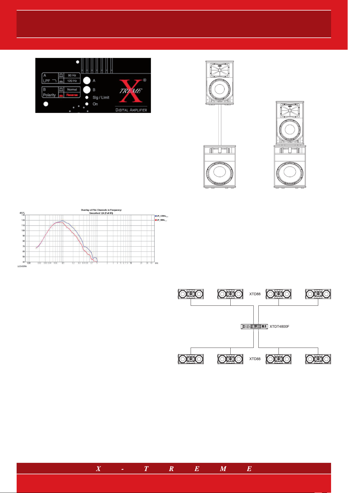
Fig. 14 Details of XTDS15/A and XTDS18/A rear panel
The two switches on amplified subwoofer modules XTDS15/A and
XTDS18/A make possible the following operations: two different low
pass cuts and polarity inversion.
The lowest frequency cut (90 Hz) is adapted correctly to the use
with the respective main modules in the Deflector line, which must
be set to “sub” mode by choosing the correct preset; the other cut
(120 Hz) can be useful if used with the respective Deflector Line main
modules, in order to create a boost wherever necessary in the 100
Hz zone, or to use the subwoofers with smaller main modules, which
are not extended so well at low frequencies. The figure shows the
subwoofer model XTDS18/A frequency response2 as an example,
with the two different low pass cuts available.
Fig. 15 Subwoofer XTDS18/A presets
2 measured on the ground with reflective floor and microphone along the axis of 2 m in
virtually anechoic conditions (measurement of impulse response and partial separation
of reflections, the first obstacle at 4 m). Input signal – 20 dBu.
In standard insulation conditions (with the main speakers resting on
the subwoofers, directly or with a stand holder), the polarity must be
rigorously set to direct mode, therefore with the switch turned off.
For this reason, the position with inverted polarity (switch down) is
marked in red on the panel in this particular case. Otherwise there
will be a pressure cancellation effect, that will lead the device to loose
efficiency in the crossover band (100 Hz zone). Polarity inversion can
only allow for a better subwoofer and upper module coupling only, if
the two cabinets are placed between them. “Better coupling” means
that in the crossover band (100 Hz zone) the system is able to supply
more sound power in the environment, which depends on the rela-
tive position between the subwoofers, upper modules and the walls
or large obstacles. Whether or not polarity inversion brings about this
improvement can be understood by listening, through direct meas-
urements or simply “by ear”.
Fig. 16 Standard configuration of
subwoofer-upper module coupling (direct polarity).
10. SYSTEM CONFIGURATIONS
The following are the standard Deflector range configurations. In
each case it is also possible to use the “halved” version, with just
one satellite and one subwoofer on each side (consequently halv-
ing the sound power supplied). The connections of two loudspeaker
systems to the same amplification channel should be in parallel. The
amplifier supply remains unchanged when going from one to two
speakers at each side, because halving the acoustic impedance
from 8 Ohm to 4 Ohm allows the amplifier to generate about twice
as much power, in other words its rated power.
Fig. 17 System configuration with XTD88
and XTDT amplifiers
8/12

User’s manual
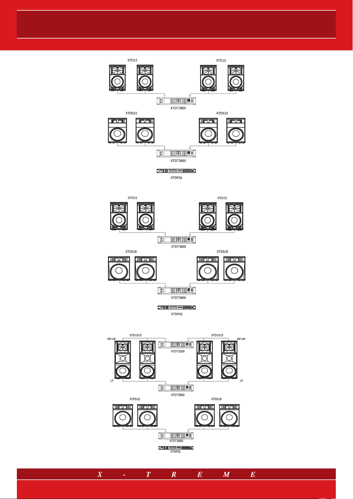
Fig. 21 Deflector 2-way type beta system configuration (with XTD12 and XTDS15, XTDT amplifiers and XTDP26 processor)
Fig. 22 System configuration with XTD15 and XTDS18, XTDT amplifiers and XTDP26 processor
Fig. 23 Deflector 3-way type beta system configuration (with XTD1015 and XTDS18, XTDT amplifiers and XTDP26 processor)
10/12
DEFLECTOR LINE
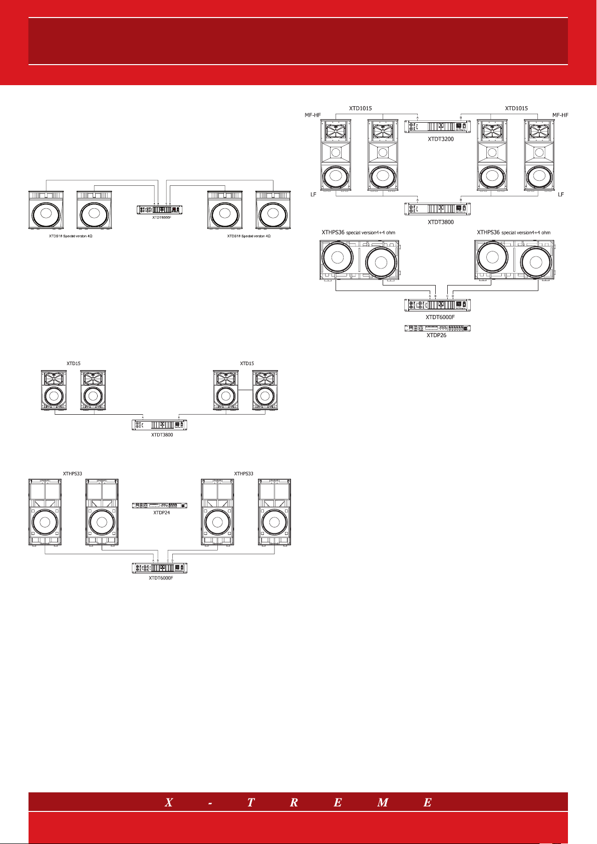
For a no-compromise dimensioning of the power supplied to the
subwoofers, X-Treme Audio also proposes the following special con-
figuration with transducers of 4 Ohm and amplification of 1500 W (@
4 Ohm) per channel, which are obtained using a XTDT6000F ampli-
fier. This configuration can replace the subwoofer section in all the
proposed configurations above.
Fig. 24 Special system configuration with 4 Ohm subwoofer
Here are two more configurations, both set up with the X-Treme “Big
punch” subwoofer in order to reach maximum performance at low
frequencies.
The coupling of two transducers and the increasing total cabinet vol-
ume give the system greater low frequency extension and higher
overall efficiency, for a more powerful and vivid listening experience.
Fig. 25 Deflector 2-way type gamma
system configuration
(with XTD15 and XTHPS33, XTDT amplifiers and XTDP24processor)
Fig. 26 Deflector 3-way type gamma
system configuration
(with XTD1015 and XTHPS36, XTDT amplifiers and XTDP26 processor)
11/12
12/12
Contacts
X-Treme Audio reserves the rights to change or modify products and specifications at any time without prior notice.
X-Treme and the corresponding symbols, images and registered trademarks are of exclusive property of Sound Corporation group. © 2010 Sound Corporation group. All rights reserved.
X-Treme Headquarters:
via Monti Urali, 33 - 42100 Reggio Emilia - Italy
tel. +39 0522 557735
fax +39 0522 391268
For general information: [email protected]
For commercial information: sales@x-tremeaudio.com
For technical support/information: [email protected]
www.x-tremeaudio.com
This manual suits for next models
11
Table of contents
Popular Subwoofer manuals by other brands

HELIX
HELIX DEEP BLUE 12 datasheet

Citronic
Citronic CX-1000BR user manual

Pioneer
Pioneer TS-W304R instruction manual

Roadmaster
Roadmaster 12" Subwoofer VSW120 instruction manual

Atlantic Technology
Atlantic Technology IW-28 SUB instruction manual

Magnat Audio
Magnat Audio II Series Owner's manual/warranty document


