manuals.online logo
Brands
  1. Home
  2. •
  3. Brands
  4. •
  5. QRP Labs
  6. •
  7. Transceiver
  8. •
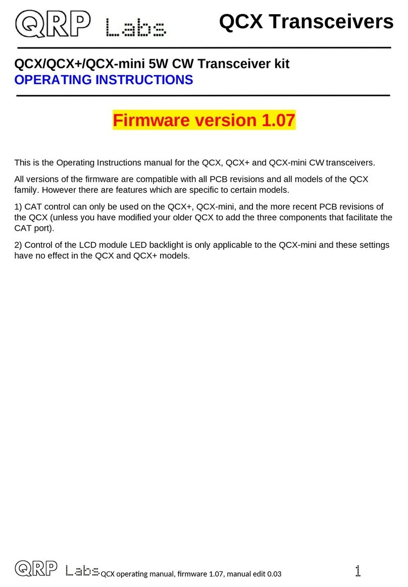
  9. QRP Labs QDX User instructions

QRP Labs QDX User instructions

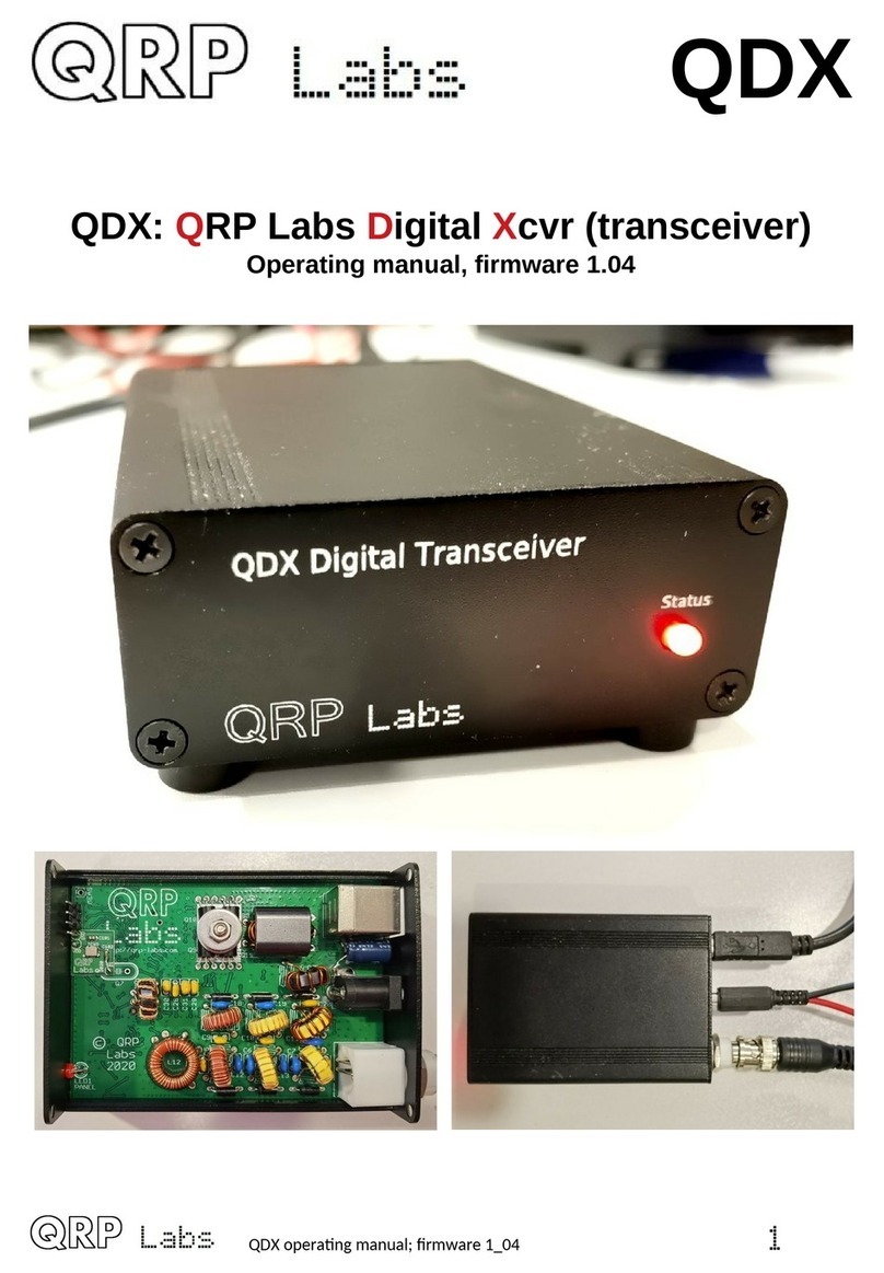
QDX
QDX: QRP Labs Digital Xcvr (transceiver)
Assembly, design and operating manual
 1

 
  
! "
#
$% # 
&$' $
(! 
'!)*+,(
- .*'
"!# ## )
/  )$
)0!1  (
/   2 *'
%)3
$
1!0### 
(#$'4 $
',#(
,# '
$  $
$5$
$67 $(
$5% 8 $'
$$5  9 0 %
$50 % #2
$(:5# 
$')0 #:# 2
$-  +
$"35;02 $
$3$: $-7#<565'
$+*  .-
$ .= -
$+:!%:#!0# 2(-
$$50 %#)0!1 ("
$>### '-
1 0<##-
(* ## -
(!+ -
(3  ## -$
(3?  ## -$
($+2 -
( 20#-"
((120#"
('# "
(-+*"
(")2"-
(1
(<#20
 2
(3?  
'!.
' #
'* #
'!0###
'$,#% 
'<0 ## $
- 
"  4 
1 Introduction
The QDX is a high performance, four-band 5W Digital modes transceiver with CAT control and
built-in SB sound card. QRP Labs presents QDX, a digital transceiver with a ratio of performance
to price not available until now.
•Four band 80, 40, 30 and 20m; 5 W from 9 – 10V supply
•Clean single signal output (zero residual carrier, zero unwanted sideband)
•Solid state PIN-diode switched Low Pass Filters and solid state Band Pass Filters
•Solid state transmit/receive switching
•High performance embedded-SDR SSB receiver using 110dB 24-bit stereo ADC chip
•Built-in SB sound card: 48ksps 24-bit stereo
•Built in SB Virtual COM port serial for CAT control
•Si5351A Synthesized local oscillator with better than 0.001Hz resolution and high precision
25MHz TCXO reference as standard
•Built-in signal generator
•Built-in suite of configuration and analysis tools
•Lifetime free firmware upgrades with QRP Labs Firmware pdate (QF ) bootloader for
easy firmware update on any OS with no extra software, or drivers, or programming
hardware
•All SMD components pre-installed by factory, only through-hole component soldering by the
kit constructor
•Receive current: 100mA; Transmit current 1.0 – 1.1A (9V supply, 5W output)
•Only three connectors: SB (audio and serial for CAT), Power and RF
•Optional smart aluminium extruded enclosure measuring just 89 x 63 x 25mm
No test equipment is required to build, align and operate this digi modes transceiver. There are no
alignment tasks.
We hope you enjoy building and operating this kit! Please read this manual carefully, and follow
the instructions step by step in the recommended order. Later in the manual the circuit design is
described in detail and we recommend reading and understanding this section too, to get the
maximum enjoyment and education from your new radio.
Typical performance measurements are shown in the measurements section. The operation
section will get you started with QDX and your WSJT-X or other digi modes software in minutes.
PLEASE READ THE BASIC ASSEMBLY AND USE INSTRUCTIONS IN
THIS MANUAL VERY CAREFULLY BEFORE APPLYING POWER TO
THE BOARD!
 3
IMPORTANT!
QDX produces 5 W power output from a supply voltage of 9V or a little over. At 12 V QDX could
be producing 8 W power output which is likely to cause over-heating and perhaps failure of the
BS170 final transistors.
Operation of QDX at more than 6W power output is NOT RECOMMENDED
If you wish to operate using a 12 V supply, you may use a two turn secondary winding on the
output transformer T1, so a 3:2 ratio instead of the 3:3 turns ratio documented in this manual.
Remember this when you come to the assembly step for preparing and installing the output
transformer T1. The “primary” is still 3 turns, with a tap half way at 1.5 turns. The secondary (no
tap) will now be only two turns.
The chart below shows the measured power output vs supply voltage for the standard 3:3 winding
(Red line); at 12 V supply the output power of around 8 W is too high and likely to cause over-
heating or failure of the power amplifier transistors. If you wish to use a supply of 12 - 13 V the 3:2
winding style is more suitable and will produce 4 – 5 W output for 12 – 13 V supply. The graph
shows 40m but other bands are very similar.
 4
2 Assembly
2 1 General guidelines
Assembly of this kit is quite straightforward, most components are SMD and have already been
pre-assembled by the PCB factory. The usual kit-building recommendations apply: work in a well-
lit area, with peace and quiet to concentrate. Some of the other semiconductors in the kit are
sensitive to static discharge Therefore, observe Electrostatic discharge (ESD) precautions.
And I say it again: FOLLOW THE INSTRUCTIONS!!
Don’t try to be a hero and do it without instructions!
A jeweler's loupe is really useful for inspecting small
components and soldered joints. You’ll need a fine-
tipped soldering iron too. It is good to get into the habit of
inspecting every joint with the magnifying glass or
jeweler's loupe (like this one I use), right after soldering.
This way you can easily identify any dry joints or solder
bridges, before they become a problem later on when
you are trying to test the project.
You could also take photos with a mobile phone, and use
the phone’s zoom features to view the board in detail.
Triple check every component value and location BEFORE soldering the component!
It is easy to put component leads into the wrong holes, so check, check and check again! It is
difficult to de-solder and replace components, so it is much better to get them correctly installed
the first time. In the event of a mistake, it is always best to detect and correct any errors as early
as possible (immediately after soldering the incorrect component). Again, a reminder: removing a
component and re-installing it later is often very difficult!
Please refer to the layout diagram and PCB tracks diagrams below, and follow the steps carefully.
Use of a good quality soldering iron and solder is highly recommended for best results!
The following diagrams show the PCB layout and track diagrams of the QDX.
Tracks shown in BL E are on the bottom layer. Tracks shown in RED are on the top layer. There
are only two layers (nothing is hidden in the middle). Not shown in this diagram are the extensive
ground-planes, on both sides of the board. Practically everything on both layers that isn’t a RED or
BL E track, is ground-plane! The two ground-planes are connected at frequent intervals (not more
than 0.1-inches) by vias.
NOTE: the capacitor lead spacing on the PCB is 0.1-inches (2.54 mm) and most of the capacitors
are sized appropriately for this. From time to time, due to availability constraints, we may have to
use capacitors with 0.2-inch lead spacing (5.08 mm); this is not a mistake, it is just due to
component availability. In this case simply use a pair of long-nosed pliers (etc) to straighten out
the wires and make them spaced for the 0.1-inch pads.
 5
 6
 7
 8
2 2 Parts list
Many components are SMD, pre-soldered to the PCB in the factory. Only through-hole
components need to be installed by the constructor. SMD components in the parts list are
identified in the Description column and by the text colour being purple.
Resistors
Qty Value Description Component numbers
3 0-ohms SMD R30, 31, 32
4 100-ohms SMD R22, 23, 24, 25
2 330-ohms SMD R2, 4
2 470-ohms SMD R28, 33
4 1K SMD R1, 6, 20, 21
1 1.5K SMD R34 (NOT INSTALLED)
12 10K SMD R3, 5, 10, 11, 12, 13, 14, 17, 18, 26, 27, 29
3 100K SMD R15, 16, 19
3 470K SMD R7, 8, 9
Capacitors (50V, Multi-layer Ceramic capacitors)
Qty Value Description Component numbers
1 22pF Label “220” C29
1 30pF Label “300” C31
2 47pF SMD C27, 32
2 56pF Label “56J” C10, 28
1 82pF Label “820” C11
1 100pF Label “101” C9
1 180pF Label “181” C20
1 220pF Label “221” C30
1 270pF Label “271” C7
2 390pF Label “391” C6, 19
2 470pF Label “471” C5, 14
2 820pF Label “821” C13, 18
1 1200pF Label “122” C12
3 10nF SMD C36, 44, 45
21 0.1uF SMD C15, 16, 17, 21, 22, 23, 24, 25, 26, 33, 35, 37, 39, 40,
41, 43, 46, 47, 49, 51, 53
11 2.2uF SMD C1, 2, 3, 4, 8, 34, 38, 42, 48, 50, 52
1 220uF 16V electrolytic Extra DC supply capacitor (see text)
 9
Semiconductors
Qty Description Component numbers
5 SMD: 1N4148 D7, 8, 9
6 1N4007 diode D1, 2, 3, 4, 5, 6
1 SMD: AMS1117-3.3 IC1
1 SMD: AMS1117-5.0 IC2
2 SMD: FST3253 IC3, 4
1 SMD: 74ACT08 IC5
1 SMD: 24C64 IC6
1 SMD: LM4562 IC7
1 STM32F401RBT6 IC8
1 AK5386 IC9
1 SMD: Si5351A 1
1 SMD: BSS84 MOSFET Q1
5 SMD: BSS123 MOSFET Q2, 3, 4, 5, 6
4 BS170: TO92 MOSFET Q8, 9, 10, 11
1 SMD: BC857 PNP T3
1 SMD: BC817 NPN T4
1 SMD: Red LED DIAG
1 3mm Red LED PANEL
Inductors
Qty Description Component numbers
6 SMD: 47uH L11, 13, 15, 16, 17, 18
4 47uH radial inductor L1, 5, 7, 9 (replace SMD inductors, see text)
1 T37-2 toroid (red), 2.40 uH (24t) L2
1 T37-2 toroid (red), 2.88 uH (26t) L6
1 T37-6 toroid (yel), 1.06 uH (18t) L3
1 T37-6 toroid (yel), 393 nH (11t) L4
1 T37-6 toroid (yel), 1.20 uH (20t) L8
1 T37-6 toroid (yel), 525 nH (13t) L10
1 T50-2 toroid – tapped, see text L12
1 FT37-43 10t L14
1 BN43-202 binocular, 3:3 T1
1 FT37-43 10t trifilar T2
 10
Miscellaneous
Qty Value Description
1 2.1 mm DC 2.1 x 5.5 barrel DC power connector
1 SB B SB type B connector
1 BNC RF connector
1 25 MHz TCXO module Replaces 25 MHz crystal – see text
1 25 MHz HC49/4H quartz crystal – NOT USED
1 PCB Main PCB, 86 c 59.5 mm
1 310 cm 0.33 mm diameter wire (AWG #28)
1 50 cm 0.60 mm diameter wire (AWG #22)
1 M3 12mm Steel 12mm long M3 screw
1 M3 Steel M3 nut
1 M3 12mm Steel 12mm diameter M3 washer
Enclosure (OPTIONAL)
Qty Value Description
2 Top, Bottom Extruded aluminium top and bottom cover
1 Front panel Laser etched, drilled for 3mm LED
1 Rear panel Laser etched, drilled for three connectors
8 M2.5 machine screw Screws to secure end panels
4 Rubber foot Self-adhesive rubber foot
 11
2 3 Inventory parts
 12
2 4 Install all the ceramic capacitors
Install all 16 through-hole capacitors in accordance with the following diagram. The procedure is
so easy that I have included all capacitors in a single assembly step rather than doing one
diagram for each capacitor value. Nevertheless be very careful to insert the correct value
capacitors in the correct places. Mistakes are hard to correct later.
In the diagram, the component label (capacitor body inscription) is written inside the capacitor
body which is coloured yellow. The actual value e.g. 220pF is written in red text next to the
capacitor. Note that the leads of the 56pF capacitor (“56J”) need to be bent to fit the 2.5mm holes.
Qty Value Description Component numbers
2 470pF Through-hole, label “471” C5, 14
2 390pF Through-hole, label “391” C6, 19
1 270pF Through-hole, label “271” C7
1 100pF Through-hole, label “101” C9
2 56pF Through-hole, label “56J” C10, 28
1 82pF Through-hole, label “820” C11
1 1200pF Through-hole, label “122” C12
2 820pF Through-hole, label “821” C13, 18
1 180pF Through-hole, label “181” C20
1 22pF Through-hole, label “220” C29
1 220pF Through-hole, label “221” C30
1 30pF Through-hole, label “300” C31
 13
2 5 Install 1N4007 diodes
Install the six 1N4007 diodes D1-D6.
Pay attention to the orientation of the diodes which is critically important. The diodes have a black
body and a white stripe. The white stripe end must be aligned with the white stripe on the image
on the PCB silkscreen. In the diagram below, all the white strip ends of the diodes are on the left
of each diode position.
So far, the assembly should
look like this →
 14
2 6 Install PA transistors
Install the transistors in the positions shown, with their flat faces flush against the PCB.
se the 12mm M3 bolt, washer and nut to firmly press the transistor faces against the PCB, as
shown.
Refer to the diagram and photographs below.
 15
2 7 Install QRP Labs QDX TCXO module
The QDX TCXO module is a small PCB containing the actual TCXO and two capacitors. It is to be
installed on the QDX PCB instead of the crystal marked “Q7”.
First use three pieces of wire, off-cuts from the capacitor leads soldered in step 3.2. Solder them in
the positions shown, soldering on the bottom side of the board (Photo, below left).
Next, slide the TCXO module onto the wires and lower it to sit flat on the main QDX PCB. Solder
the wires carefully and quickly – the TCXO PCB is only a single sided board so the pads will not
withstand a lot of heat or abuse – then carefully cut off the excess wire. The result is as shown
(photo, below right).
 16
2 8 Assemble and install transformer T1
Transformer 1 is wound on the BN43-202 binocular ferrite former, using the thick 0.6mm (AWG
#22) wire. This wire is also used for L14 so do not use all of it on the transformer. \
The transformer has two windings, both 3 turns. The three-turn primary winding has a center-tap.
In the nomenclature of binocular cored transformers, “1 turn” means the wire passes through both
sets of holes, ending up back at the end where it started.
Assembly of this transformer is best done in steps as follows. Please read all the steps before
commencing the assembly:
Step 1: Carefully unwrap the thick 0.6mm (AWG #22) wire, and straighten it ensuring there are no
kinks.
Step 2: Pass the wire through both holes, starting at the top left, as shown. This is the first turn of
the 3-turn primary winding.
Step 3: Now pass the wire through the top hole of the binocular core, back from left to right. This is
the next half-turn of the primary winding, bringing the number of turns so far to 1.5; now we must
make the center tap.
 17
Step 4: Now pass the wire back through the bottom hole of the binocular core, from right to left;
but do not pull it tight. Leave a small loop as shown in the photograph. This will be soldered into
the center-tap pad on the PCB.
Step 5: Wind the wire through both the top hole of the binocular core and the bottom hole, pulling
it a little tight as normal; this forms the final turn of the 3-turn primary winding. You end up with the
wire coming out of the bottom left hole as shown; cut it to about 1cm protrusion.
Step 6: Squeeze together the center-tap to try to avoid subsequent confusion.
Step 7: Start the 3-turn secondary winding by pushing the wire from right to left through the bottom
hole of the binocular core, then from left to right through the top hole. This is the first turn.
Step 8: Push the wires through both holes two
more times to create the second turn: right to left
through the bottom hole, then left to right through
the top hole. Now we have three turns on the
secondary. Cut the wire leaving about 1cm spare.
 18
Step 9: Bend all the wires to point downward in
the position they will need to be, to fit through the
holes in the PCB.
Step 10: Now cut the center-tap loop; hopefully,
as mine are in this photograph, these two wires
formed by cutting the loop are LONGER than the
two ends of the 3-turn secondary, so that you
cannot mix anything up.
Step 11: Insert the wires into the holes on the
PCB. The two wires (of the cut loop) that belong
to the center-tap of the 3-turn primary, which are
the longer wires, are inserted into the middle hole
on the right-hand side; this hole is larger than the others and is big enough for both wires to fit in.
Step 12: Now we need to get the enamel off the wire. sually on thinner wire, I hold the soldering
iron to the wire until the enamel burns off. But that doesn’t work so well on thicker wire such as
this. So my technique here is to scrape the enamel off, at least partially, using wire cutters. The
correct pressure needs to be applied to the wire cutters, so as NOT to actually cut the wire. I hold
the wire cutter as close to the PCB as possible, then gently but firmly pull the cutter away from the
PCB, scratching off the enamel. Turn the cutter to a different angle and scrape again, 2 or 3 times.
It is not necessary to remove ALL the enamel, if you get a few good scrapes on, enough enamel
will be removed that the soldering iron heat will burn off the rest of the enamel and a good joint will
be achieved. Do this for the 4 winding ends first, leave the two center-tap for later, to make it
easier.
Step 13: Cut each of the four wire-endings, leaving about 2mm or less, sticking up from the PCB.
 19
Step 14: Solder the four wire endings. At each pad, hold the soldering iron firmly, apply plenty of
solder, and wait for about 10 seconds. This will ensure a good connection, and any remaining
enamel will be burned away.
Step 15: Finally repeat the procedure with the two center-tap wires that came through the large
center hole. Scrape them, cut them to 2mm, and solder them. Apply plenty of solder and hold the
soldering iron tip to the joint for maybe 15 seconds, to really be sure of a good joint and burning
away any remaining enamel.
Step 16: Check that none of the wires protrude more than 2mm from the surface of the PCB, since
if you are using the optional aluminium enclosure, there are only a few mm clearance.
Step 17: Verify good connections for all five soldered joints of T1 using a DMM set to resistance or
continuity mode. My cheap DMM hasn’t got a continuity mode and I’m using the 2000-ohm
resistance mode; in this mode when there is continuity, the reading on mine shows 001 (not zero-
ohms; this is just a DMM thing, of no significance).
 20

Other manuals for QDX

2

Other QRP Labs Transceiver manuals

QRP Labs QMX User manual

QRP Labs

QRP Labs QMX User manual

QRP Labs QDX User manual

QRP Labs

QRP Labs QDX User manual

QRP Labs QCX 5W CW User manual

QRP Labs

QRP Labs QCX 5W CW User manual

QRP Labs QDX User manual

QRP Labs

QRP Labs QDX User manual

QRP Labs QCX-mini CW User manual

QRP Labs

QRP Labs QCX-mini CW User manual

QRP Labs QCX-mini User manual

QRP Labs

QRP Labs QCX-mini User manual

QRP Labs QCX Operating instructions

QRP Labs

QRP Labs QCX Operating instructions

QRP Labs QMX User manual

QRP Labs

QRP Labs QMX User manual

QRP Labs QCX User manual

QRP Labs

QRP Labs QCX User manual

Popular Transceiver manuals by other brands

Albrecht AE 540 user manual

Albrecht

Albrecht AE 540 user manual

Kenwood TS-940S instruction manual

Kenwood

Kenwood TS-940S instruction manual

Quicksilver 2M 70CM user manual

Quicksilver

Quicksilver 2M 70CM user manual

NavWorx ADS600-B Installation and user manual

NavWorx

NavWorx ADS600-B Installation and user manual

Kenwood NEXEDGE NX-200S instruction manual

Kenwood

Kenwood NEXEDGE NX-200S instruction manual

Russound BTC-2 manual

Russound

Russound BTC-2 manual

ADI AT-201 user manual

ADI

ADI AT-201 user manual

Yaesu FT DX 9000 CONTEST -  2 brochure

Yaesu

Yaesu FT DX 9000 CONTEST - 2 brochure

Alinco DR-620 Service manual

Alinco

Alinco DR-620 Service manual

Sommerkamp FT DX-500 manual

Sommerkamp

Sommerkamp FT DX-500 manual

Albrecht Tectalk Pro XL quick start guide

Albrecht

Albrecht Tectalk Pro XL quick start guide

Yaesu FT-70DR operating manual

Yaesu

Yaesu FT-70DR operating manual

LuxCom OMT-8B operating instructions

LuxCom

LuxCom OMT-8B operating instructions

Kenwood TK-630H Service manual

Kenwood

Kenwood TK-630H Service manual

Kenwood TR-7400A operating manual

Kenwood

Kenwood TR-7400A operating manual

Amateur FTM-400DR 144 Product review

Amateur

Amateur FTM-400DR 144 Product review

HP ProCurve Gigabit-SX installation guide

HP

HP ProCurve Gigabit-SX installation guide

National Instruments PXIe-5646R Getting started guide

National Instruments

National Instruments PXIe-5646R Getting started guide

manuals.online logo
manuals.online logoBrands
  • About & Mission
  • Contact us
  • Privacy Policy
  • Terms and Conditions

Copyright 2025 Manuals.Online. All Rights Reserved.