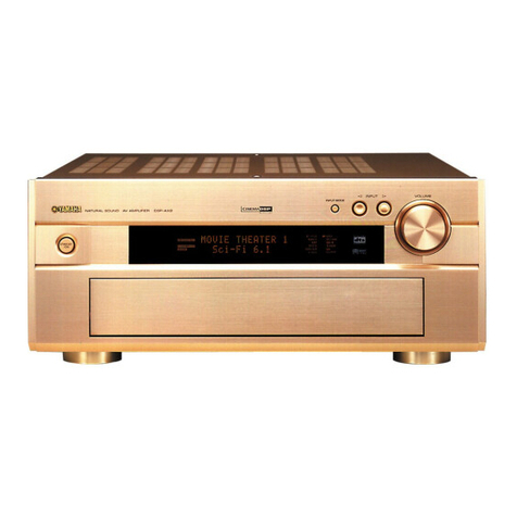
Yamaha DSP-AX1/RX-V1 User manual

DSP-AX1/RX-V1
DSP-AX1/RX-V1
AV AMPLIFIER/AV RECEIVER
100698
■ CONTENTS
TO SERVICE PERSONNEL ........................................... 1
FRONT PANELS ............................................................. 2
REAR PANELS ........................................................... 3~4
SPECIFICATIONS ....................................................... 5~8
INTERNAL VIEW ............................................................ 9
DISASSEMBLY PROCEDURES .............................. 9~10
SELF DIAGNOSIS FUNCTION............................... 11~32
AMP ADJUSTMENTS ................................................... 33
TUNER ADJUSTMENTS ........................................ 34~37
IC DATA .................................................................. 38~53
PRINTED CIRCUIT BOARD ................................... 54~83
BLOCK DIAGRAM .................................................. 84~88
PIN CONNECTION DIAGRAM ..................................... 89
SCHEMATIC DIAGRAM ....................................... 90~101
PARTS LIST ........................................................ 102~135
REMOTE CONTROL TRANSMITTER................ 136~141
This manual has been provided for the use of authorized YAMAHA Retailers and their service personnel.
It has been assumed that basic service procedures inherent to the industry, and more specifically YAMAHA Products, are already
known and understood by the users, and have therefore not been restated.
WARNING: Failure to follow appropriate service and safety procedures when servicing this product may result in personal
injury, destruction of expensive components, and failure of the product to perform as specified. For these
reasons, we advise all YAMAHA product owners that any service required should be performed by an
authorized YAMAHA Retailer or the appointed service representative.
IMPORTANT: The presentation or sale of this manual to any individual or firm does not constitute authorization, certification
or recognition of any applicable technical capabilities, or establish a principle-agent relationship of any
form.
The data provided is believed to be accurate and applicable to the unit(s) indicated on the cover. The research, engineering, and
service departments of YAMAHA are continually striving to improve YAMAHA products. Modifications are, therefore,
inevitable and specifications are subject to change without notice or obligation to retrofit. Should any discrepancy appear to exist,
please contact the distributor's Service Division.
WARNING: Static discharges can destroy expensive components. Discharge any static electricity your body may have
accumulated by grounding yourself to the ground buss in the unit (heavy gauge black wires connect to this
buss).
IMPORTANT: Turn the unit OFF during disassembly and part replacement. Recheck all work before you apply power to the
unit.
IMPORTANT NOTICE
DSP-AX1/RX-V1
SERVICE MANUAL

DSP-AX1/RX-V1
DSP-AX1/RX-V1
■ TO SERVICE PERSONNEL
1. Critical Components Information.
Components having special characteristics are marked Z
and must be replaced with parts having specifications equal
to those originally installed.
2. Leakage Current Measurement (For 120V Models Only).
When service has been completed, it is imperative to verify
that all exposed conductive surfaces are properly insulated
from supply circuits.
●Meter impedance should be equivalent to 1500 ohm shunted
by 0.15µF.
●Leakage current must not exceed 0.5mA.
AC LEAKAGE
TESTER OR
EQUIVALENT
EQUIPMENT
UNDER TEST
INSULATING
TABLE
WALL
OUTLET
1
WARNING: CHEMICAL
CONTENT NOTICE!
The solder used in the production of this product
contains LEAD. In addition, other electrical/
electronic and/or plastic (where applicable)
components may also contain traces of chemicals
found by the California Health and Welfare
Agency (and possibly other entities) to cause
cancer and/or birth defects or other reproductive
harm.
DO NOT PLACE SOLDER, ELECTRICAL/
ELECTRONIC OR PLASTIC COMPONENTS IN
YOUR MOUTH FOR ANY REASON
WHATSOEVER!
Avoid prolonged, unprotected contact between
solder and your skin! When soldering, do not
inhale solder fumes or expose eyes to solder/flux
vapor!
If you come in contact with solder or components
located inside the enclosure of this product, wash
your hands before handling food.
IMPEDANCE SELECTOR
WARNING
Do not change the IMPEDANCE SELECTOR
switch setting while the power to this unit is
on, otherwise this unit may be damaged.
●Be sure to test for leakage with the AC plug in both
polarities.
“CAUTION”
“F751 : FOR CONTINUED PROTECTION AGAINST RISK OF FIRE, REPLACE ONLY WITH SAME TYPE 12A, 250V FUSE.”
CAUTION
F751 : REPLACE WITH SAME TYPE 12A, 250V FUSE.
ATTENTION
F751 : UTILISER UN FUSIBLE DE RECHANGE DE MEME TYPE DE 12A, 250V.
AV

DSP-AX1/RX-V1
DSP-AX1/RX-V1
2
▼ DSP-AX1
▼ RX-V1
■FRONT PANELS

DSP-AX1/RX-V1
DSP-AX1/RX-V1
3
▼ DSP-AX1 R, T models
■REAR PANELS
CCIB
▼ DSP-AX1 B model
▼ DSP-AX1 G model
*

DSP-AX1/RX-V1
DSP-AX1/RX-V1
4
▼ RX-V1 U model
▼ RX-V1 C model
▼ RX-V1 A model

DSP-AX1/RX-V1
DSP-AX1/RX-V1
5
■ AUDIO SECTION
Minimum RMS Output Power per Channel
MAIN, 20Hz to 20kHz, 0.015% THD, 8Ω. . . .110W+110W
CENTER, 20Hz to 20kHz, 0.015% THD, 8Ω. . . . . . 110W
REAR, 20Hz to 20kHz, 0.015% THD, 8Ω. . .110W+110W
REAR CENTER,
20Hz to 20kHz, 0.015% THD, 8Ω. . . . . . . . . . . . . . 110W
FRONT, 1kHz, 0.05% THD, 8Ω. . . . . . . . . . . . .35W+35W
Maximum Power per Channel (R, T models only)
MAIN, 1kHz, EIAJ, 10% THD, 8Ω. . . . . . . . .150W+150W
CENTER, 1kHz, EIAJ, 10% THD, 8Ω. . . . . . . . . . . 150W
REAR, 1kHz, EIAJ, 10% THD, 8Ω. . . . . . . . .150W+150W
REAR CENTER, 1kHz, EIAJ, 10% THD, 8Ω. . . . . . 150W
FRONT, 1kHz, EIAJ, 10% THD, 8Ω. . . . . . . . . .45W+45W
Dynamic Power per Channel (U, C, R, T models only)
MAIN, 8/6/4/2Ω. . . . . . . . . . . . . . . . . . . 150/180/240/340W
Dynamic Headroom (U, C, R, T models only)
8Ω. . . . . . . . . . . . . . . . . . . . . . . . . . . . . . . . . . . . . . 1.3dB
DIN Standard Output Power per Channel (B, G models only)
MAIN, 1kHz, 0.7% THD, 4Ω. . . . . . . . . . . . . .180W+180W
CENTER, 1kHz, 0.7% THD, 4Ω. . . . . . . . . . . . . . . . 180W
REAR, 1kHz, 0.7% THD, 4Ω. . . . . . . . . . . . .180W+180W
REAR CENTER, 1kHz, 0.7% THD, 4Ω. . . . .180W+180W
FRONT, 1kHz, 0.7% THD, 4Ω. . . . . . . . . . . . . .60W+60W
IEC Power (B, G models only)
MAIN, 1kHz, 0.015% THD, 8Ω. . . . . . . . . . . . . . . . . 120W
Power Band Width
MAIN, 0.04% THD, 55W/8Ω. . . . . . . . . . . . 10Hz to 50kHz
Damping Factor
MAIN/CENTER, 20Hz to 20kHz, 8Ω. . . . . . . 200 or more
Input Sensitivity/Impedance
PHONO MM . . . . . . . . . . . . . . . . . . . . . . . . . . 2.5mV/47kΩ
CD, etc . . . . . . . . . . . . . . . . . . . . . . . . . . . . . 150mV/47kΩ
MAIN IN . . . . . . . . . . . . . . . . . . . . . . . . . . . . . . . . . 1V/47kΩ
Maximum Input Signal Level
PHONO MM, 1kHz, 0.05% THD, (Effect on) . . . . . 100mV
CD, etc, (Effect on) . . . . . . . . . . . . . . . . . . . . . . . . . . . 2.3V
Output Level/Impedance
REC OUT . . . . . . . . . . . . . . . . . . . . . . . . . . . 150mV/600Ω
PRE OUT (MAIN, etc) . . . . . . . . . . . . . . . . . . . . . 1V/1.2kΩ
SUB WOOFER (EFFECT OFF, MAIN SP : SMALL)
SPLIT . . . . . . . . . . . . . . . . . . . . . . . . . . . . . . . . . . . .
2.0V/1.2kΩ
MONO . . . . . . . . . . . . . . . . . . . . . . . . . . . . . . . . . . .
4.0V/1.2kΩ
Maximum Voltage Output (20Hz to 20kHz, 1% THD)
PRE OUT (MAIN L/R) . . . . . . . . . . . . . . . . . . . . . . . . . . . 3V
Headphone Jack Rated Output/Impedance
CD, etc, (40mV, 8Ω) . . . . . . . . . . . . . . . . . . . 150mV/100Ω
Frequency Response (10Hz to 100kHz)
CD, etc, MAIN L/R . . . . . . . . . . . . . . . . . . . . . . . +0/-3.0dB
RIAA Equalization Deviation (20Hz to 20kHz)
PHONO MM . . . . . . . . . . . . . . . . . . . . . . . . . . . . . 0±0.5dB
Tone Control Characteristics
BASS : Boost/cut . . . . . . . . . . . . . . . . . . . ±10dB (50Hz)
Turnover Frequency . . . . . . . . . . . . . . . . 350Hz
TREBLE : Boost/cut . . . . . . . . . . . . . . . . . . ±10dB (20kHz)
Turnover Frequency . . . . . . . . . . . . . . . 3.5kHz
Center Graphic Equalizer
Frequency . . . . . . . . . . . . 100/300/1k/3k/10kHz
Boost/cut . . . . . . . . . . . . . . . . . . . . . . . . . . ±6dB
Q . . . . . . . . . . . . . . . . . . . . . . . . . . . . . . . . . 0.7
Bass Extension . . . . . . . . . . . . . . . . . . . . . . . . . . +6dB (60Hz)
Filter Characteristics
SUB WOOFER OUT : L.P.F. . . . . . . fc = 90Hz, 24dB/oct.
■SPECIFICATIONS
■VIDEO SECTION
Video Signal Type
U, C models . . . . . . . . . . . . . . . . . . . . . . . . . . . . . . . NTSC
A, B.G models . . . . . . . . . . . . . . . . . . . . . . . . . . . . . . . .PAL
R, T models . . . . . . . . . . . . . . . . . . . . . . . . . . . . NTSC/PAL
Composite Video Signal Level . . . . . . . . . . . . . . 1Vp-p/75Ω
S-Video Signal Level
Y . . . . . . . . . . . . . . . . . . . . . . . . . . . . . . . . . . . . 1Vp-p/75Ω
C . . . . . . . . . . . . . . . . . . . . . . . . . . . . . . . . . 0.286Vp-p/75Ω
Component Signal Level
Y . . . . . . . . . . . . . . . . . . . . . . . . . . . . . . . . . . . . 1Vp-p/75Ω
Cb/Cr . . . . . . . . . . . . . . . . . . . . . . . . . . . . . . . . . . 0.7V/75Ω
Video Maximum Input Level . . . . . . . . . . . . . . . . . . . 1.5Vp-p
Video Signal-to-Noise Ratio . . . . . . . . . . . . . . . . . . . . . 50dB
Monitor Output Frequency Response
Composite Video Signal . . . . . . . . . . . . 5Hz~10MHz, –3dB
S-Video Signal . . . . . . . . . . . . . . . . . . . . 5Hz~10MHz, –3dB
Component Signal . . . . . . . . . . . . . . . . . DC~20MHz, –3dB
Cinema Equalizer
HIgh Frequency . . . . . . . . . . . . . . . .1kHz to 12.7kHz
Boost/cut . . . . . . . . . . . . . . . . . . . -9dB to +6dB
PEQ Frequency . . . . . . . . . . . . . . . .1kHz to 12.7kHz
Boost/cut . . . . . . . . . . . . . . . . . . . -9dB to +6dB
Q . . . . . . . . . . . . . . . . . . . . . . . . . . . . . . . . 1.85
Total Harmonic Distortion (20Hz to 20kHz)
PHONO MM to REC OUT (1V) . . . . . . . . . . . . . . . . 0.01%
CD, etc, to PRE OUT MAIN L/R (1V) . . . . . . . . . . 0.005%
MAIN IN to L/C/R SP OUT (55W/8Ω) . . . . . . . . . . 0.005%
Signal-to-Noise Ratio (IHF-A-Network)
PHONO MM, Input Shorted 5mV (Effect off) . . . . . . . 86dB
CD, etc, Input Shorted (Effect off) . . . . . . . . . . . . . . . 96dB
Residual Noise (IHF-A-Network)
MAIN, SP OUT . . . . . . . . . . . . . . . . . . . . . . . . . . . . . 150µV
Channel Separation (Vol. –30dB, Effect off)
PHONO MM, Input Shorted, 1kHz/10kHz . . . . 70dB/60dB
CD, etc, Input 5.1kΩShorted, 1kHz/10kHz . . . 70dB/60dB
Muting . . . . . . . . . . . . . . . . . . . . . . . . . . . . . . . . . . . . . . . . –∞

DSP-AX1/RX-V1
DSP-AX1/RX-V1
6
■ FM SECTION (RX-V1 only)
Tuning Range
U, C models . . . . . . . . . . . . . . . . . . . . . . .87.5 to 107.9MHz
A models . . . . . . . . . . . . . . . . . . . . . . .87.50 to 108.00MHz
50dB Quieting Sensitivity (IHF, 75 Ω)
U, C models only
Mono (1kHz, 100% Mod.) . . . . . . . . . . . . 1.6µV (15.3dBf)
Stereo (1kHz, 100% Mod.) . . . . . . . . . . . . 23µV (38.5dBf)
Usable Sensitivity (DIN, 75 Ω)
A model only
Mono (S/N 26dB) . . . . . . . . . . . . . . . . . . . . . . . . . . 0.9µV
Stereo (S/N 46dB) . . . . . . . . . . . . . . . . . . . . . . . . . . . 28µV
Alternate Channel Selectivity (±400Hz)
U, C models . . . . . . . . . . . . . . . . . . . . . . . . . . . . . . . . . 75dB
Selectivity (two signals, 40kHz Dev.) (±300Hz)
A model . . . . . . . . . . . . . . . . . . . . . . . . . . . . . . . . . . . . 55dB
Signal-to-Noise Ratio
U, C models
Mono/Stereo (IHF) . . . . . . . . . . . . . . . . . . . . . . . 81/75dB
A model
Mono/Stereo (DIN-weighted, 40kHz Dev.) . . . . . 75/69dB
Harmonic Distortion
Mono/Stereo (1kHz) . . . . . . . . . . . . . . . . . . . . . . . 0.1/0.2%
Stereo Separation
1kHz . . . . . . . . . . . . . . . . . . . . . . . . . . . . . . . . . . . . . . . 48dB
Frequency Response
20Hz to 15kHz . . . . . . . . . . . . . . . . . . . . . . . . . . . . 0±1.0dB
Output Level
U, C models
FM 100% mod. 1kHz . . . . . . . . . . . . . . . . . . . . . . 550mV
A models
FM 40kHz Dev. 1kHz . . . . . . . . . . . . . . . . . . . . . . 550mV
Antenna Input . . . . . . . . . . . . . . . . . . . . . . . 75 Ωunbalanced
■AM SECTION (RX-V1 only)
Tuning Range
U, C models . . . . . . . . . . . . . . . . . . . . . . . .530 to 1,710kHz
A model . . . . . . . . . . . . . . . . . . . . . . . . . . .531 to 1,611kHz
Usable Sensitivity . . . . . . . . . . . . . . . . . . . . . . . . . . 300µV/m
Output Level
AM 30% mod. 1kHz . . . . . . . . . . . . . . . . . . . . . . . . 150mV
Signal-to-Noise Ratio . . . . . . . . . . . . . . . . . . . . . . . . . . 52dB
Antenna . . . . . . . . . . . . . . . . . . . . . . . . . . . . . . . Loop antenna
■GENERAL
Power Supply
U, C models . . . . . . . . . . . . . . . . . . . . . . . AC 120V, 60Hz
A model . . . . . . . . . . . . . . . . . . . . . . . . . . . AC 240V, 50Hz
B, G models . . . . . . . . . . . . . . . . . . . . . . . AC 230V, 50Hz
R, T models . . . . . . . . . . . AC 110/120/220/240V, 50/60Hz
Power Consumption
U model . . . . . . . . . . . . . . . . . . . . . . . . . . . . . . . . . . . 550W
C model . . . . . . . . . . . . . . . . . . . . . . . . . . . . . 550W/700VA
A, R, T models . . . . . . . . . . . . . . . . . . . . . . . . . . . . . 550W
Maximum Power Consumption (R, T models only) . . 770W
AC Outlets
U, R, T, G models, Switched x 3 . . . . . 100W max (Total)
C model, Switched x 3 . . . . . 100W max/1.0A max (Total)
A, B models, Switched x 1 . . . . . . . . . . . . . . . . 100W max
Dimensions (W x H x D) . . . . . . . . . . . 471 x 211.5 x 473mm
(18-9/16”x 8-5/16”x 18-5/8”)
Weight . . . . . . . . . . . . . . . . . . . . . . . . . .28.0 kg (61 lbs 11oz)
Finish
RX-V1 . . . . . . . . . . . . . . . . . . . . . . . Gold color/Black color
DSP-AX1 . . . . . . . . . . . . . . . . . . . . Gold color/Black color
Accessories
RX-V1 only . . . . . . . . . . . . . . . . . . . AM loop antenna x 1
Indoor FM antenna x 1
DSP-AX1/RX-V1 . . . . . . . Remote Control Transmitter x 1
Battery (size "AA", "R06") x 3
* Specifications subject to change without notice.
U . . . . . . . . . . USA model
C . . . . . .Canadian model
A . . . . . Australian model
B . . . . . . . . British model
G . . . . . European model
R . . . . . . . General model
T . . . . . . . . . China model
● DIMENSIONS
471 (18-9/16")
21
(13/16") 190.5 (7-1/2")
211.5 (8–5/16")
22.5
(7/8") 21.5
(7/8")
429 (16-7/8")
473 (18–5/8")
Units : mm (inch)
Manufactured under license from Dolby Laboratories.
"Dolby", "AC-3", "Pro Logic", and the double-D symbol V
are trademarks of Dolby Laboratories. © 1992-1997 Dolby
Laboratories. All rights reserved.
Manufactured under license from Digital Theater Systems,
Inc. US Pat. No. 5,451,942 and other world-wide patents
issued and pending. "DTS", "DTS Digital Surround", are
trademarks of Digital Theater Systems, Inc. copyright
1996 Digital Theater Systems, inc. All rights reserved.

DSP-AX1/RX-V1
DSP-AX1/RX-V1
● SET MENU TABLE
No. SET MENU PRESET VALUE SETTING RANGES
1. SPEAKER SET
1A CENTER SPEAKER LARGE LARGE/SMALL/NONE
1B MAIN SPEAKER LARGE LARGE/SMALL
1C REAR L/R SPEAKER LARGE LARGE/SMALL/NONE
1D REAR CT SPEAKER LARGE LARGE/SMALL/NONE
1E LFE/BASS OUT BOTH SUBWOOFER/MAIN/BOTH
1F FRONT EFCT SPEAKER YES YES/NONE
1G MAIN LEVEL NORMAL NORMAL/–10dB
2. LOW FREQ. TEST TONE : OFF ON/OFF
OUTPUT : MAIN L/R L/C/R/RS/RC/LS/SW/FRONT
FREQUENCY : 88Hz 35 —250Hz
3. DOLBY DIGITAL SET
3A LFE LEVEL SPEAKER : 0dB –20dB —0dB
HEAD PHONE : 0dB –20dB —0dB
3B DYNAMIC RANGE SPEAKER : MAX MAX/STD/MIN
HEAD PHONE : MAX MAX/STD/MIN
4. DTS SET
4A LFE LEVEL SPEAKER : 0dB –10dB —+10dB
HEAD PHONE : 0dB –10dB —+10dB
5. SPEAKER DELAY TIME CENTER : 0ms 0ms —5ms
REAR CENTER : 3ms 0ms —30ms
6. AUDIO DELAY 0ms 0ms —99ms
7. CENTER GRAPHIC EQ. EACH ch : 0dB 100Hz —10kHz, –6dB —+6dB
8. REAR CENTER GRAPHIC EQ. EACH ch : 0dB 100Hz —10kHz, –6dB —+6dB
9. CINEMA EQ. ALL “OFF”
L, C, R/FRONT EFCT//REAR L,R/REAR CT ON/OFF
9A L, C, R EQ. HIGH 12.7kHz, –3dB PEG 12.7kHz, –4dB HIGH, PGE : 1kHz —12.7kHz
9B FRONT EFCT EQ. HIGH 12.7kHz, 0dB PEG 8kHz, –3dB GAIN : –9dB —+6dB
9C REAR L/R EQ. HIGH 12.7kHz, 0dB PEG 8kHz, –3dB
9D REAR CENTER EQ. HIGH 12.7kHz, 0dB PEG 8kHz, –3dB
10. HP TONE CTRL BASS : 0dB –6dB —+3dB
TREBLE : 0dB –6dB —+3dB
11. PARAMETER INITIALIZE OFF PROGRAM 1 —12
12. 6.1/ES AUTO ON ON/OFF
13. MEMORY GUARD OFF ON/OFF
14. COMPONENT VIDEO INPUT [A] : DVD
DVD, LD, D-TV, CBL/SAT, VCR1, VCR2, VCR3, V-AUX
[B] : D-TV
DVD, LD, D-TV, CBL/SAT, VCR1, VCR2, VCR3, V-AUX
[C] : CBL/SAT
DVD, LD, D-TV, CBL/SAT, VCR1, VCR2, VCR3, V-AUX
15. INPUT MODE D-TV : AUTO AUTO/LAST
CBL/SAT : AUTO AUTO/LAST
VCR1 : AUTO AUTO/LAST
16. INPUT RENAME LD(Currently selected input)
17. DIMMER 0 –4 —0
18. ZONE2 SET ZONE2 OUT : FIX FIX/VAR
S : S video signal
V : Composite video signal
O : YES
X:NO
—: NO CARE
Caution: Superimposing function is not usable for component signals.
● SUPERIMPOSING
Input LD, etc. Output Superimposing
Terminal Signal Monitor connection
S O O O (On screen)
VO —X
SO X X
VO —O (On screen)
S O O O (On screen)
VX —X
SO X X
VX —O (Blue back)
SX —X
VO —X (On screen)
SX —O (Blue back)
VX —O (Blue back)
7

DSP-AX1/RX-V1
DSP-AX1/RX-V1
Sub-program
Name
[ SP MODE ]
Europe Hall A
Europe Hall B
Europe Hall C
U.S.A. Hall D
Europe Hall E
Live Concert
Tokyo
Freiburg
Royaumont
Village Gate
VillageVanguard
The Bottom Line
Roxy Theatre
Warehouse Loft
Arena
Disco
Party
Game/Amusement
Pop/Rock
DJ
Classical/Opera
Pavilion
Mono Movie
Variety/Sports
Spectacle
Sci-Fi
Adventure
General
Normal
Enhanced
(P.)INIT.DLY
ms 30
30
30
35
30
45
40
95
69
21
26
30
15
15
15
26
15
45
21
23
28
23
49
10
13
16
15
15
(P.)ROOM
SIZE 1.0
1.0
1.0
1.0
1.0
1.0
1.0
1.0
1.0
1.0
1.0
1.0
1.0
1.0
1.0
1.0
1.0
1.0
1.0
1.0
1.0
1.0
(P.)LIVENESS
5
5
5
5
5
5
3
3
3
3
5
5
5
5
7
5
5
5
2
S.DELAY
(2ch) ms
25
30
30
30
30
23
20
20
20
20
20
S.DELAY
(DD/dts) ms
10
5
5
5
5
5
15
15
15
5
5
5
7
8
8
12
12
12
5
5
5
5
8
8
15
15
15
15
5
5
S.INIT.DLY
(DD/dts) ms
31
31
31
20
12
32
2
12
23
19
S.INIT.DLY
(DD+EX/dts+ES) ms
31
31
31
20
12
32
2
12
23
19
S.ROOM SIZE
(2ch)
1.0
1.0
1.0
1.0
1.0
1.0
1.0
1.0
1.0
1.0
S.ROOM SIZE
(DD/dts)
1.0
1.0
1.0
1.0
1.0
1.0
1.0
1.0
1.0
1.0
S.ROOM SIZE
(DD+EX/dts+ES)
1.0
1.0
1.0
1.0
1.0
1.0
1.0
1.0
1.0
1.0
S.LIVENESS
(2ch)
4
S.LIVENESS
(DD/dts)
4
S.LIVENESS
(DD+EX/dts+ES)
4
RC.INIT.DLY
ms
15
15
15
15
15
15
15
15
15
15
RC.ROOM
SIZE
1.0
1.0
1.0
1.0
1.0
1.0
1.0
1.0
1.0
1.0
RC.LIVENESS
5
REV.TIME
s
2.5
4.0
4.0
1.6
2.0
2.0
2.7
2.5
2.5
2.2
2.5
2.5
1.6
REV.DELAY
ms
122
130
120
100
160
120
120
140
130
120
142
160
100
REV.LEVEL
%
56
55
52
7
6
8
4
4
10
1
4
2
4
EFCT TRIM
db 0
0
0
0
0
0
0
0
0
0
0
0
0
0
0
0
0
0
0
0
0
0
0
0
0
0
0
0
Sub-program
Name
[ HP MODE ]
Europe Hall A
Europe Hall B
Europe Hall C
U.S.A. Hall D
Europe Hall E
Live Concert
Tokyo
Freiburg
Royaumont
Village Gate
VillageVanguard
The Bottom Line
Roxy Theatre
Warehouse Loft
Arena
Disco
Party
Game/Amusement
Pop/Rock
DJ
Classical/Opera
Pavilion
Mono Movie
Variety/Sports
Spectacle
Sci-Fi
Adventure
General
Normal
Enhanced
(P.)INIT.DLY
ms 30
32
30
35
30
45
40
95
69
21
26
30
15
15
28
26
15
45
21
23
28
23
45
10
13
21
16
15
(P.)ROOM
SIZE 1.0
1.0
1.0
1.0
1.0
1.0
1.0
1.0
1.0
1.0
1.0
1.0
1.0
1.0
1.0
1.0
1.0
1.0
1.0
1.0
1.0
1.0
(P.)LIVENESS
5
5
5
5
5
5
3
3
3
3
5
5
5
5
7
5
5
5
2
S.DELAY
(2ch) ms
25
30
30
30
30
23
20
20
20
20
20
S.DELAY
(DD/dts) ms
10
5
5
5
5
5
15
15
15
5
5
5
7
8
8
12
12
12
5
5
5
5
8
8
8
8
8
15
5
5
S.INIT.DLY
(DD/dts) ms
31
30
18
20
12
32
16
32
23
19
S.INIT.DLY
(DD+EX/dts+ES) ms
31
30
18
20
12
32
16
12
23
19
S.ROOM SIZE
(2ch)
1.0
1.0
1.0
1.0
1.0
1.0
1.0
1.0
1.0
1.0
S.ROOM SIZE
(DD/dts)
1.0
1.0
1.0
1.0
1.0
1.0
1.0
1.0
1.0
1.0
S.ROOM SIZE
(DD+EX/dts+ES)
1.0
1.0
1.0
1.0
1.0
1.0
1.0
1.0
1.0
1.0
S.LIVENESS
(2ch)
4
S.LIVENESS
(DD/dts)
3
S.LIVENESS
(DD+EX/dts+ES)
3
RC.INIT.DLY
ms
15
15
15
15
15
15
15
15
15
15
RC.ROOM
SIZE
1.0
1.0
1.0
1.0
1.0
1.0
1.0
1.0
1.0
1.0
RC.LIVENESS
5
REV.TIME
s
2.5
4.0
4.0
1.6
2.0
2.0
2.7
2.5
2.5
2.2
2.5
2.5
1.6
REV.DELAY
ms
122
117
120
100
160
120
120
140
110
120
142
160
100
REV.LEVEL
%
56
55
52
7
6
8
4
4
10
2
4
2
4
EFCT TRIM
db
●
PARAMETER TABLE
8

DSP-AX1/RX-V1
DSP-AX1/RX-V1
■INTERNAL VIEW
qPOWER TRANSFORMER
wSUB TRANS P. C. B. (1)
eMAIN P. C. B. (4)
rVIDEO P. C. B. (4)
tVIDEO P. C. B. (1)
ySUB TRANS P. C. B. (5)
uSUB TRANS P. C. B. (3)
iVIDEO P. C. B. (2)
oVIDEO P. C. B. (3)
!0 DSP P. C. B. (1)
!1 MAIN P. C. B. (2)
!2 SUB TRANS P. C. B. (4)
!3 DSP P. C. B. (2)
!4 VIDEO P. C. B. (5)
!5 SUB TRANS P. C. B. (2)
!6 MAIN P. C. B. (3)
!7 MAIN P. C. B. (1)
!8 VIDEO P. C. B. (9)
!9 FUNCTION P. C. B. (1)
q u
!2 !3 !8!4 !6 !7
ow
!1 !5 !9
te r y i !0
■DISASSEMBLY PROCEDURES (Remove parts in the order as numbered.)
1. Removal of Top Cover
a. Remove 8 screws ( q) and then slide the Side Panel
to remove it in Fig. 1.
b. Remove 2 screws ( w) and 2 screws ( e) and then
remove the Top Cover in Fig. 1.
2. Removal of Bottom Cover
a. Remove 12 screws ( r) and then remove the Bottom
Cover in Fig. 1.
3. Removal of Front Panel
a. Remove 2 knobs in Fig. 1.
b. Remove 4 screws ( t) and then slide the Panel/Side
forward to remove it in Fig. 1.
c. Remove 4 screws ( y) and then remove the Front
Panel in Fig. 1.
Fig. 1
9
q
q
w
e
r
r
r
r
t
t
Bottom Cover
Front Panel
Top Cover
Side Panel
Side Panel
q
q
y
y
Panel/Side
Panel/Side

DSP-AX1/RX-V1
DSP-AX1/RX-V1
Note :
1.When the rear panel has been removed, the ground
wire of the input/output pin jack becomes loose.
Connect it to the chassis by using a lead wire.
5. Removal of Main P.C.B. (2)
a. Remove 2 screws ( o) and remove the left Plate
Side in Fig. 3.
a. Remove 6 screws ( !0 ) and then remove the left Side
Frame in Fig. 3.
6. Removal of Main P.C.B. (3)
a. Remove 4 screws ( !1 ) and remove the center Upper
Frame in Fig. 4.
b. Remove 6 screws ( !2 ) and then take up the Sub
Chassis in Fig. 4.
Fig. 2
Fig. 3 Fig. 4
4. Removal of DSP P.C.B. (1)
a. Remove 2 screws ( u) and remove the right Plate
Side in Fig. 2.
b. Remove 15 screws ( i) and remove the right Upper
Frame in Fig. 2.
10
i
i
i
i
i
Upper Frame (right)
DSP (1)
!0
!0
!0
!0
Side Frame (L) MAIN (2)
!2
!2
MAIN (3)
u
Plate Side
(R)
o
Plate Side (L)
!2!2
!2
!1
!1
!1
Upper Frame
(center)

DSP-AX1/RX-V1
DSP-AX1/RX-V1
■SELF DIAGNOSIS FUNCTION
This product has a built-in self diagnosis function (DIAG) to facilitate inspection, measurement and determination of a faulty
item, if any. There are 14 DIAG menu items each of which has sub-menu items.
Listed in the table below are menu items and sub-menu items.
DIAG menu
DSP THROUGH
DECODER THROUGH
RAM THROUGH
PRO LOGIC
BYPASS
SPEAKERS SET
DISPLAY CHECK
MANUAL TEST
RS-232C
PRESET
FAN/AD
IF STATUS (0 –18)
Sub-menu
1. ANALOG BYPASS
2. DSP 0dB
3. DSP FULL BIT
1. YSS918/908
2. DSP FULL BIT
1. 2ch/MULTI
2. DSP FULL BIT
1. YSS918
2. YSS908
3. EFFECT OFF
1. DECODER
2. DSP
1. MAIN:SMALL 0dB
2. MAIN:LARGE -10
3. CENTER:NONE
4. LFE/BASS:MAIN
5. FRONT MIX:5ch
6. CENTER:SMALL
7. REAR:SMALL
1. EFFECT OFF (initial screen)
2. DISPLAY OFF
3. DISPLAY ALL
4. DISPLAY DIMMER (50%)
5. CHECKED PATTERN
1. ALL
2. MAIN L
3. CENTER
4. MAIN R
5. REAR R
6. REAR C
7. REAR L
8. FRONT L
9. FRONT R
10. LFE
1. TX DATA
2. HARD FLOW
1. INHIBIT (memory initialization inhibited)
2. RESERVED (memory initialized)
1. FAN HISTORY
2. KY0, KY1(PANEL KEY)
3. MTR, THM, PRD, PRV
1. SCPU
2. VER
3. SUM
4. CHS1
5. CHS2
6. CHS3
7. CHS4
8. CHS5
9. BSI1
10. BSI2
Remote control code (key)
7A---90 (PRG 9)
7A---91 (PRG 10)
7A---92 (PRG 11)
7A---93 (PRG 12)
7A---10
(TUNER PRESET +)
7A---11
(TUNER PRESET -)
7A---12
(TUNER A/B/C/D/E)
7A---9C (SET DOWN)
7A---9D (SET UP)
7A---9E (SET INC)
7A---9F (SET DEC)
---------
7A---88 (PRG 1)
7A---89 (PRG 2)
7A---8A (PRG 3)
7A---8B (PRG 4)
7A---8C (PRG 5)
7A---8D (PRG 6)
7A---8E (PRG 7)
7A---8E (PRG 8)
---------
---------
---------
---------
7A---00 (TAPE PLAY)
7A---01 (TAPE RW)
7A---02 (TAPE FW)
7A---03 (TAPE STOP)
7A---04 (TAPE PAUSE)
7A---05 (TAPE MUTE)
7A---06 (TAPE A/B)
7A---07 (TAPE DIR A)
7A---08 (CD PLAY)
7A---09 (CD STOP)
---------
---------
---------
---------
---------
---------
7A---56 (EFFECT)
---------
---------
---------
---------
---------
---------
---------
---------
---------
---------
No.
1
2
3
4
5
6
7
8
9
10
11
12
11

DSP-AX1/RX-V1
DSP-AX1/RX-V1
No.
12
13
14
DIAG menu
IF STATUS
DSP RAM CHECK
SUM/VER/PORT
Sub-menu
11. BSI3
12. BSI4
13. BSID
14. DIR5
15. Y918
16. Y908
17. DSP6
18. RAM1
19. RAM2
#1, #2 (DSP RAM check)
1. M, S (main/sub checksum)
2. M, S (main/sub version)
3. PORT (setting confirmation of function setting port)
4. REC-OUT (confirmation of REC OUT port)
Remote control code (key)
---------
---------
---------
---------
---------
---------
---------
---------
---------
---------
---------
---------
---------
---------
●Starting DIAG
For DSP-AX1:
Press the “POWER”(STANDBY/ON) key of the main unit while pressing the “SET MENU+”key and the “NEXT”key
located in the sealing panel of the main unit, and DIAG will be activated.
For RX-V1:
Press the “POWER”(STANDBY/ON) key of the main unit while pressing the “PROGRAM w”key and the “EFFECT”
key located in the sealing panel of the main unit, and DIAG will be activated.
●Starting DIAG in the protection cancel mode
If the power supply, amplifier protection function is activated and hinders the trouble diagnosis, cancel the protec-
tion function as described below, and it will be possible to enter the DIAG mode. (The protection function other than
the excess current detect function will be cancelled.)
For DSP-AX1:
Press the “POWER”(STANDBY/ON) key while pressing the “SET MENU+”key and the “NEXT”key. At this time,
keep pressing the “SET MENU+”key and the “NEXT”for 3 seconds or longer.
For RX-V1:
Press the “POWER”(STANDBY/ON) key while pressing the “PROGRAM w”key and the “EFFECT”key. At this
time, keep pressing the “PROGRAM w”key and the “EFFECT”key for 3 seconds or longer.
In this mode, “V”in the FL display of the main unit flashes.
CAUTION!
Using this product with the protection function cancelled may cause damage to itself. Use special care for this point
when using this mode.
●Canceling DIAG
Turn off the power by pressing the “POWER”(STANDBY/ON) key of the main unit or the “STANDBY”key of the
remote control unit.
CAUTION: When canceling this function, check that DIAG menu No.10 PRESET (memory initialization inhibited/
reserved) has been set. (To keep the user memory, be sure to select “INHIBIT”(initialization inhibited) from the
No.10 PRESET menu before canceling the DIAG function.)
12

DSP-AX1/RX-V1
DSP-AX1/RX-V1
1.DSP THR 8.MAN TST
2.DECODE THR 9.RS232C
3.RAM THR 10.PRESET
4.PRO LOGIC 11.AD DATA
5.DECODE BYP 12.STATUS
6.SP SET 13.DSP RAM
7.E.OFF DIS 14.SUM VER
DIAGNOSTIC MENU
●Display at the start of DIAG
The diagnostic menu appears on the monitor screen. (It remains on display until it is canceled.)
On the FL display of the main unit, an opening message (including the version and the history of
protection function) appears for a few seconds followed by the diagnostic menu display of 1 DSP
THROUGH: ANALOG BYPS.
Version of the main/sub mi-
croprocessor (1 alphabet)
Opening message
Checksum of the main
microprocessor
NO PROTECT X X
M:XXXX S:XXXX
Checksum of the sub
microprocessor
DIAG menu display
1. DSP THROUGH
ANALOG BYPS
When there is no history
of protection function (*1)
(*1) If the history of the protection function has been recorded, the type of the protection function and
the voltage value recorded last are displayed.
Checksum (4 figures consisting of alphabets and numbers)
The checksum is obtained by adding 4M bits per 1 octo of the entire program code and expressing the result as a
4-figure hexadecimal data. (0xff is added for the area where no code has been entered and for the area other than
ROM code.)
13

DSP-AX1/RX-V1
DSP-AX1/RX-V1
In the case where the protection function works after DIAG has been started and the power is turned off ;
When the protection function (*2) works, the history of the protection function appears on display and the power
turns off. Repair the faulty parts according to the displayed history.
(*2) When an excess current or any other faulty condition is found with the power source, DC, etc., the protection
function forces the power to turn off.
I PROTECTION display
(When the power is turned on without an abnormality corrected, the protec-
tion function works the moment the power relay is turned on to shut off the
power supply.)
Cause: There is an abnormal current flow to the power amplifier.
Supplementary information: If I PROTECTION function has worked after
SP relay ON, a warning message “CHECK SP WIRES”appears the next
time the power is turned on. This indicates that some trouble exists after
the SP terminal, such as a short-circuit of the speaker cable.
PS PRT display
(When the power is turned on without an abnormality corrected, the
protection function works about 1 second later to shut off the power supply.
Display may not be provided, if there is an abnormality with the power
supply for the display.)
Cause: There is an abnormality in the power supply section (voltage).
Supplementary information: As the power from following sources is
detected, it is possible to determine where an abnormality exists.
Transformer secondary winding
VI X 2(CB704), YE x 2(CB482)
U, C only : GY x 2(CB481)
Stabilizing power source
±12, ±5V, +5D1, +5D2, +3.3, VP
DC PRT display
(When the power is turned on without an abnormality corrected, the protec-
tion function works about 3 seconds later to shut off the power supply.)
Cause: A DC output from the power amplifier is detected in the bad
channel.
TMP PRT display
(When the power is turned on without an abnormality corrected, the protec-
tion function works about 3 seconds later to shut off the power supply.)
Cause: The temperature of the heat sinks in the power amplifier is
detected. When the temperature rises and an abnormality is detected, the
power turns off.
I PROTECT X X
M:XXXX S:XXXX
PS PRT :000 X X
M:XXXX S:XXXX
DC PRT :000 X X
M:XXXX S:XXXX
TMP PRT:000 X X
M:XXXX S:XXXX
●History of protection function
When the protection function has worked, its history is stored in memory with a backup. Even when no abnormality is noted while
the unit is being serviced, an abnormality which has occurred previously can be defined as long as the backup data has been
stored.
The protection history is cleared when DIAG is canceled by selecting “RESERVED”(memory initialization) from the setting items
of the DIAG menu No.10 PRESET or when the backup data is erased.
Besides the above possible causes, the cause may exist in the disconnected connector or around CPU.
PS PRT, DC PRT and TMP PRT displays include the abnormal A/D value in % (voltage value obtained by consid-
ering 5V as 100%). Concerning this value, refer to DIAG menu No.11 FAN/AD described on page 28.
14

DSP-AX1/RX-V1
DSP-AX1/RX-V1
●Operation procedure of DIAG menu and SUB-MENU
There are No.1 to No.14 MENU items and some SUB-MENU items as well.
DIAG menu selection
DSP-AX1 Main unit: PROGRAM w(forward)/q(reverse) key
RX-V1 Main unit: PRESET TUNING + (forward)/-(reverse) key
SUB-MENU selection
DSP-AX1 Main unit: SET MENU + (forward)/-(reverse) key
RX-V1 Main unit: PROGRAM w(forward)/q(reverse) key
Remote control unit: Only the remote control key in the Menu List can directly call a sub menu.
●Functions during DIAG being set
In addition to the DIAG menu, functions as listed below are available.
•Input selection (including ZONE2), 6CH input
•REC OUT switching
•ZONE2 input, volume
•Front/Center/Rear/Sub-woofer level adjustment
•Muting
•Speaker A/B
•Power on/off operation
•Master volume
It is possible to set to the following volume values using the remote control unit
only during DIAG being set.
•Functions related to the tuner and the set menu are not available.
•It is possible to confirm Menu No.12 IF STATUS while keeping the signal process (operation status)
of each DIAG menu by using the INPUT MODE key of the main unit.
●Initial settings used to start DIAG function
Following initial settings are used when starting the DIAG function.
When the DIAG function is canceled, the settings before starting DIAG will be restored.
•Input, ZONE2 input: LD (6CH INPUT OFF)
•Master volume: -40dB
•ZONE2 volume: -6dB
•Front/Center/Rear/Sub-woofer level: 0dB
•Audio mute: OFF
•Speaker A/B: ON
Volume value (dB)
0
-21
-35
MUTE
Remove control code (key)
7A---E0 (PAGE A)
7A---E1 (PAGE B)
7A---E2 (PAGE C)
7A---E3 (PAGE D)
15

DSP-AX1/RX-V1
DSP-AX1/RX-V1
1. DSP THROUGH
There are 3 sub menu items (ANALOG BYPS, DSP 0dB, FULL BIT).
Details of DIAG menu
In each menu, “SPEAKERS”is always set to “LARGE”, D-RANGE to “MAX”, LFE LEVEL to 0dB (-10dB when
DOLBY DIGITAL is used) and CENTER DELAY to 0ms unless otherwise specified.
AC3D2av outputs signals using 2ch though. (L/F)
•DSP6#1outputs the L/R input signals to C/LFE(SD611),RLef/RRef (SD613), FL/FR (SD614),
RC (SD615, L only).
•DSP6#2 outputs the output signals from DSP6#1 to C/RC (SD621), RL/RR (SD623), FL/FR
(SD622), SWL/SWR (SD624).
Note: (SDxxx) represents a terminal name of DSP6#1 and DSP6#2.
ANALOG BYPS [Remote control code: 7A—90(PRG 9)]
•The input mode is fixed to use the analog (A/D) system.
•The L/R signal is output through the analog bypass without using the DSP section.
•C/RC, RL/RR, FL/FR, SWL/SWR signals are output using L/R through via DSP.
1. DSP THROUGH
ANALOG BYPS
AC3D2av
YSS918
PCM THR
DSP6#2YSS910
A/D
AK5383
ANALOG
SWL
SWR
FILTER
DF1704
D/A
PCM1704
D/A
PCM1704
RL
RR
FILTER
DF1704
D/A
PCM1704
D/A
PCM1704
FL
FR
FILTER
DF1704
D/A
PCM1704
D/A
PCM1704
C
RC
FILTER
DF1704
D/A
PCM1704
D/A
PCM1704
L
R
DSP6#1YSS910
L/R
C/LFE
LFE
RLef/RRef
FL/FR
RC/ZERO
RC FL/FR
RL/RR
SWL/SWR
C/RC
IC3
IC6
IC7 IC8
IC4
1. DSP THROUGH
DSP 0dB
1. DSP THROUGH
FULL BIT
16
RLef : RL EFFECT
RRef : RR EFFECT
ZERO : Digital 0
CD ANALOG IN : –20dBV, Both ch
VOLUME : MAX
PRE OUT
MAIN L (1kHz) : –3.7dBV
MAIN R (1kHz) : –3.7dBV
CENTER (1kHz) : –3.2dBV
REAR CENTER (1kHz) : –3.4dBV
FRONT L (1kHz) : –3.5dBV
FRONT R (1kHz) : –3.4dBV
REAR L (1kHz) : –3.4dBV
REAR R (1kHz) : –3.3dBV
SW L (50Hz) : –3.3dBV
SW R (50Hz) : –3.3dBV
SW MONO (50Hz) : + 2.7dBV
Reference

DSP-AX1/RX-V1
DSP-AX1/RX-V1
DSP 0dB [Remote control code: 7A—91 (PRG 10)]
The input signal is automatically identified and switched in the priority order of dts > DOLBY DIGITAL > PCM
AUDIO >Analog (A/D) according to the signal detection.
The L/R, C/LFE, FL/FR, RL/RR, RC signals are output through DSP.
(In the case of 2-ch source)
•AC3D2av outputs signals using 2ch though. (L/R)
•DSP6#1 outputs the L/R input signals to L/R (SD610), C/LFE (SD611), RLef/RRef (SD613), FL/FR (SD614), RC
(SD615, L only).
•DSP6#2 outputs the output signals of DSP6#1 to L/R (SD620), C/RC (SD621), RL/RR (SD623), FL/FR (SD622),
SWL/SWR (SD624).
(In the case of multi-ch source)
•AC3D2av outputs signals using DOLBY DIGITAL/dts decode operation.
•DSP6#1 outputs the L/R input signals to L/R (SD610), RC (SD615, Lonly), C/LFE to C/LFE (SD611),
LSt/RSt to RLdr/RRdr (SD612), FL/FR (SD614) respectively.
•DSP6#2 outputs the output signals of DSP6#1 to L/R (SD620), C/RC (SD621), RL/RR (SD623), FL/
FR (SD622), SWL/SWR (SD624).
FULL BIT [Remote control code: 7A—92 (PRG11)]
The head margin is unused and the digital data is output in full bit.
The same applies as “DSP 0dB”except that the digital data is output in full bit at D/A.
17
RLdr : RL DIRECT
RRdr : RR DIRECT
DIR5
YSD917
AC3D2av
YSS918
PCM THR
DSP6#2YSS910
A/D
AK5383
DIGITAL
ANALOG
SWL
SWR
FILTER
DF1704
D/A
PCM1704
D/A
PCM1704
RL
RR
FILTER
DF1704
D/A
PCM1704
D/A
PCM1704
FL
FR
FILTER
DF1704
D/A
PCM1704
D/A
PCM1704
C
RC
FILTER
DF1704
D/A
PCM1704
D/A
PCM1704
L
R
FILTER
DF1704
D/A
PCM1704
D/A
PCM1704
DSP6#1YSS910
L/R
L/R
FL/FR
RC
LFE
RL/RR
SWL/SWR
C/RC
L/R
C/LFE
RLef/RRef
FL/FR
RC/ZERO
IC3
IC6
IC7 IC8
IC2
IC4
IC57
CD ANALOG IN : –20dBV, Both ch
VOLUME : MAX
PRE OUT
MAIN L (1kHz) : –3.5dBV
MAIN R (1kHz) : –3.5dBV
CENTER (1kHz) : –3.2dBV
REAR CENTER (1kHz) : –3.4dBV
FRONT L (1kHz) : –3.5dBV
FRONT R (1kHz) : –3.4dBV
REAR L (1kHz) : –3.4dBV
REAR R (1kHz) : –3.4dBV
SW L (50Hz) : –3.4dBV
SW R (50Hz) : –3.4dBV
SW MONO (50Hz) : + 2.7dBV
Reference
DIR5
YSD917
AC3D2av
YSS918
DD/dts
DECODE
DSP6#2YSS910
A/D
AK5383
DIGITAL
ANALOG
SWL
SWR
FILTER
DF1704
D/A
PCM1704
D/A
PCM1704
RL
RR
FILTER
DF1704
D/A
PCM1704
D/A
PCM1704
FL
FR
FILTER
DF1704
D/A
PCM1704
D/A
PCM1704
C
RC
FILTER
DF1704
D/A
PCM1704
D/A
PCM1704
L
R
FILTER
DF1704
D/A
PCM1704
D/A
PCM1704
DSP6#1YSS910
L/R
C/LFE
LSt/RSt
L/R
C/LFE
RLdr/RRdr
FL/FR
RC/ZERO
FL/FR
RL/RR
SWL/SWR
C/RC
L/R
RC
LFE
IC3
IC6
IC7 IC8
IC2
IC4
IC57
CD DIGITAL IN : 1kHz, –20dBV
VOLUME : MAX
PRE OUT
MAIN L : + 4.2dBV
MAIN R : + 4.2dBV
CENTER : + 4.5dBV
REAR CENTER : + 4.2dBV
FRONT L : + 4.2dBV
FRONT R : + 4.3dBV
REAR L : + 4.3dBV
REAR R : + 4.3dBV
Reference
CD ANALOG IN : –30dBV, Both ch
VOLUME : MAX
PRE OUT
MAIN L (1kHz) : –7.5dBV
MAIN R (1kHz) : –7.5dBV
CENTER (1kHz) : –7.2dBV
REAR CENTER (1kHz) : –7.5dBV
FRONT L (1kHz) : –7.5dBV
FRONT R (1kHz) : –7.5dBV
REAR L (1kHz) : –1.4dBV
REAR R (1kHz) : –1.4dBV
SW L (50Hz) : + 7.5dBV
SW R (50Hz) : + 7.5dBV
SW MONO (50Hz) : + 13.5dBV
Reference

DSP-AX1/RX-V1
DSP-AX1/RX-V1
2. DECODER THR.
The input signal is automatically identified and switched in the priority order of dts > DOLBY DIGITAL
> PCMAUDIO >Analog (A/D). There are two sub-menu items (YSS918/908, FULL BIT). This menu is
used to check the signal passage of the decoder LSI (YSS918, YSS908).
2. DECODER THR.
YSS918 908
2. DECODER THR.
FULL BIT
YSS918/908 [Remote control code: 7A—93 (PRG12)]
(In the case of 2-ch source)
•AC3D2av outputs L/R input signals from L/R (SDA200, Lt/Rt (SDA21) and C/LFE (SDA22).
•AC3D2av outputs the Lt/Rt output signals of AC3D2av from LS/RS (SDA10).
•DSP6#1 outputs the L/R input signals to L/R (SD610) and RC (SD615, L only), C/LFE (SD611) input
signals to C/LFE (SD611), Lt/Rt input signals to FL/FR (SD614) and LS/RS input signals to RLdr/
RRdr (SD612) respectively.
•DSP6#2 outputs the output signals of DSP6#1 to L/R (SD620), C/RC (SD621), RL/RR (SD623), FL/
FR (SD622) and SWL/SWR (SD624).
Note: (SDAxx) represents the terminal name of AC3Dav and AC3D2av.
(SDxxx) represents the terminal name of DSP6#1 and DSP6#2.
(In the case of multi-ch source)
•AC3D2av outputs dts or DOLBY DIGITAL encoded input signals from Lt/Rt (SDA21) without decod-
ing.
•AC3Dav processes Lt/Rt output signals of AC3D2av by dts or DOLBY DIGITAL decoding and out-
puts them to LS/RS (SDA10) and RC (SDA12, L only) through 3/0 down-mixing.
•DSP6#1 outputs the LS/RS input signals to RLdr/RRdr (SD612) and the RC (L only) input signals to
RC (SD615, L only).
•DSP6#2 outputs the output signals of DSP6#1 to RC (SD621, R only) and RL/RR (SD623).
18
DIR5
YSD917
AC3D2av
YSS918
PCM THR
DSP6#2YSS910
AC3Dav
YSS908
DD/dts
DECODE
A/D
AK5383
DIGITAL
ANALOG
SWL
SWR
FILTER
DF1704
D/A
PCM1704
D/A
PCM1704
RL
RR
FILTER
DF1704
D/A
PCM1704
D/A
PCM1704
FL
FR
FILTER
DF1704
D/A
PCM1704
D/A
PCM1704
C
RC
FILTER
DF1704
D/A
PCM1704
D/A
PCM1704
L
R
FILTER
DF1704
D/A
PCM1704
D/A
PCM1704
DSP6#1YSS910
L/R
C/LFE
Lt/Rt
Lt/Rt
LS/RS
L/R
C/LFE
RLdr/RRdr
FL/FR
RC/ZERO
FL/FR
RL/RR
SWL/SWR
C/RC
L/R
RC
LFE
IC3
IC6
IC7 IC8
IC2
IC5
IC4
IC57
CD ANALOG IN : –20dBV, Both ch
VOLUME : MAX
PRE OUT
MAIN L (1kHz) : –3.5dBV
MAIN R (1kHz) : –3.4dBV
CENTER (1kHz) : –3.2dBV
REAR CENTER (1kHz) : –3.4dBV
FRONT L (1kHz) : –3.5dBV
FRONT R (1kHz) : –3.4dBV
REAR L (1kHz) : –3.4dBV
REAR R (1kHz) : –3.3dBV
SW L (50Hz) : –3.3dBV
SW R (50Hz) : –3.3dBV
SW MONO (50Hz) : + 2.7dBV
Reference
DIR5
YSD917
AC3D2av
YSS918
PCM THR
DSP6#2YSS910
AC3Dav
YSS908
DD/dts
DECODE
A/D
AK5383
DIGITAL
ANALOG RL
RR
FILTER
DF1704
D/A
PCM1704
D/A
PCM1704
RC
FILTER
DF1704
D/A
PCM1704
DSP6#1YSS910
Lt/Rt
Lt/Rt
LS/RS
RC/ZERO
RLdr/RRdr RC
RC/ZERO
RL/RR
RC
IC3
IC6
IC7 IC8
IC2
IC5
IC4
CD DIGITAL IN : 1kHz, –20dBV
VOLUME : MAX
PRE OUT
MAIN L : + 4.5dBV
MAIN R : + 4.6dBV
CENTER : + 4.9dBV
REAR CENTER : + 4.6dBV
FRONT L : + 4.6dBV
FRONT R : + 4.6dBV
REAR L : + 4.7dBV
REAR R : + 4.7dBV
Reference

DSP-AX1/RX-V1
DSP-AX1/RX-V1
3. RAM THROUGH
2ch MULTI
3. RAM THROUGH
FULL BIT
FULL BIT [Remote control code: 7A—10 (TUNER PRESET +)]
The head margin is unused and the digital data is output in full bit.
The same applies as YSS918/908 except that the digital data is output in full bit at D/A.
3. RAM THROUGH
The input data is automatically identified and switched in the priority order of dts > DOLBY DIGITAL >
PCM AUDIO > Analog (A/D) according to the signal detection.
The main L/R uses the analog through method when analog signals are input and the DSP through
method when digital signals are input.
There are two sub-menu items (2ch/MULTI, FULL BIT).
2ch/MULTI [Remote control code: 7A—11 (TUNER PRESET -)]
(In the case of 2-ch source)
•AC3D2av outputs signals using 2ch though. (L/R)
•DSP6#1 outputs the L/R input signals to L/R (SD610), C/LFE (SD611) and RC (SD615, Lonly). Also,
it outputs L/2 + R/2 to RLef/RRef (SD613) and FL/FR (SD614) through the external RAM.
•DSP6#2 outputs the output signals of DSP6#1 to L/R (SD620), RL/RR (SD623), FL/FR (SD622),
SWL/SWR (SD624).Also, it outputs C/RC to C/RC (SD621) through the external RAM.
19
CD ANALOG IN : –30dBV, Both ch
VOLUME : MAX
PRE OUT
MAIN L (1kHz) : –7.5dBV
MAIN R (1kHz) : –7.5dBV
CENTER (1kHz) : –7.2dBV
REAR CENTER (1kHz) : –7.5dBV
FRONT L (1kHz) : –7.5dBV
FRONT R (1kHz) : –7.4dBV
REAR L (1kHz) : –1.4dBV
REAR R (1kHz) : –1.3dBV
SW L (50Hz) : + 7.6dBV
SW R (50Hz) : + 7.5dBV
SW MONO (50Hz) : + 13.7dBV
Reference
DIR5
YSD917
AC3D2av
YSS918
PCM THR
DSP6#2YSS910
A/D
AK5383
4M DRAM
DIGITAL
ANALOG
4M DRAM
SWL
SWR
FILTER
DF1704
D/A
PCM1704
D/A
PCM1704
RL
RR
FILTER
DF1704
D/A
PCM1704
D/A
PCM1704
FL
FR
FILTER
DF1704
D/A
PCM1704
D/A
PCM1704
C
RC
FILTER
DF1704
D/A
PCM1704
D/A
PCM1704
L
R
FILTER
DF1704
D/A
PCM1704
D/A
PCM1704
DSP6#1YSS910
L/R
L/R
C/LFE
LFE
C/RC
RLef/RRef
FL/FR
L/2
+
R/2 RC/ZERO
FL/FR
RL/RR
SWL/SWR
C/RC
L/R
IC3
IC6
IC7 IC8
IC2
IC33
IC34 IC35
IC4
IC57
CD ANALOG IN : –20dBV, Both ch
VOLUME : MAX
PRE OUT
MAIN L (1kHz) : –3.5dBV
MAIN R (1kHz) : –3.4dBV
CENTER (1kHz) : –3.2dBV
REAR CENTER (1kHz) : –3.4dBV
FRONT L (1kHz) : –3.4dBV
FRONT R (1kHz) : –3.4dBV
REAR L (1kHz) : –3.4dBV
REAR R (1kHz) : –3.3dBV
SW L (50Hz) : –3.3dBV
SW R (50Hz) : –3.3dBV
SW MONO (50Hz) : + 2.7dBV
Reference
Other manuals for DSP-AX1/RX-V1
1
Table of contents
Other Yamaha Amplifier manuals

Yamaha
Yamaha B-2 User manual

Yamaha
Yamaha DSP-AX1/RX-V1 User manual

Yamaha
Yamaha A-520 User manual

Yamaha
Yamaha DSP-A2 User manual

Yamaha
Yamaha TX4n User manual

Yamaha
Yamaha AX-596 User manual

Yamaha
Yamaha XP5000 User manual

Yamaha
Yamaha AX-492, AX-592, AX-892 User manual

Yamaha
Yamaha PC1602 User manual

Yamaha
Yamaha THR30II Wireless User manual

Yamaha
Yamaha A-1 User manual

Yamaha
Yamaha RX-V2500 User manual

Yamaha
Yamaha BBT 500H User manual

Yamaha
Yamaha RX-V3300 User manual

Yamaha
Yamaha AVX-700 User manual

Yamaha
Yamaha CX-830RS User manual

Yamaha
Yamaha B-2x User manual

Yamaha
Yamaha P2180 User manual

Yamaha
Yamaha AX-397 User manual

Yamaha
Yamaha MX-A5200 Instruction manual