manuals.online logo
Brands
  1. Home
  2. •
  3. Brands
  4. •
  5. Channel Vision
  6. •
  7. Amplifier
  8. •
  9. Channel Vision A0360 User manual

Channel Vision A0360 User manual

A0360
100W Flush Mount Audio Amplifier
with Bluetooth, Cat5 Audio and Tos-Link
Digital Input Source
18
The A0360 Table-Top Amplifier can be used with Channel Vision’s CAT5
audio hubs to provide a powerful 100 Watt Amplifier, 50Watts per channel in
the listening zone with an output for a powered sub-woofer.
Features:
100 Watt integrated class D amplifier
Optical Tos-Link Local audio input from a TV or music system
Cat-5 input for use with Channel Vision’s CAT5 audio systems
Volume Control & source selection using A0125 keypad
IR Remote receiver built in
Integrated IR Repeating
Cascade multiple amplifiers together with individual control or
at the same time
CAUTION
RISK OF ELECTRIC SHOCK
DO NOT OPEN !
IMPORTANT SAFETY INSTRUCTIONS
1. Read these instructions.
2. Keep these instructions for future reference.
3. Heed all warnings.
4. Follow all instructions.
5. Do not use this device near water.
6. Clean only with a dry cloth.
7. Do not block any ventilation openings. Install in accordance with these
instructions.
8. Do not install near any heat sources such as radiators, heat registers,
stoves, or other apparatus that produce heat.
9. This apparatus must not be exposed to dripping or splashing water and
no objects filled with liquids, such as vases, shall be placed on the
apparatus.
10. Protect the power cord from being walked on or pinched particularly at
plugs, convenience receptacles, and the point where they exit from the
apparatus.
11. Unplug this apparatus during lightning storms or when unused for long
periods of time.
12.
Warning: To reduce the risk of electric shock, do not remove the cover (or
back), no user serviceable parts inside, refer servicing to qualified service
personnel.
IR Receiver EYE
IR Extension 3.5mm
Link Button
Optical Audio input
Power input front or back
24VDC, 2.5Amp
8 ohm
Speaker Output
CAT5 Input
Connect the
output of your
Cat5 Output
Can also be used as keypad input
Rear Power Access Green connector located under top circuit board.
16AWG recommended. 24VDC 2.5Amp
A0501, A0502, or A0505 ... Remote control. Contains IR
codes for controlling the Amplified Wireless Audio Receiver
as well as many other Channel Vision audio products.
A0125 keypad controller ... IR repeating keypad.
A0125 contains the IR codes to operate the volume controls
in the P-2014 or P-2044 Matrix. You may also use a 3.5mm
IR receiver on the faceplate. When using the faceplate IR
receiver, you will need to use the A0505 remote control
which contains the IR codes to control the A0360. IR codes
can be downloaded from www.channelvision.com, or
learned from an A0505 remote control.
IR Volume can be learned from your existing TV remote
3.5mm IR-receiver
The
Pwr Mute
Vid 1
Vid 2
Vid 3
Vid 4
Vol
+
Vol
-
TM
CHANN EL VISION
S
O
U
R
C
E
ZONE
POWER
MUTE
VOL
1
2
3
4
MODEL
A0501
POWER
Accessories & Complementary Products (sold separately)
In-wall, In-ceiling Speakers, and Free Standing
Speakers... Channel Vision offers a full line of premium
speakers. These speakers are perfect for whole-house music
or home theater applications.
Accessories (In the Box)
24VDC, 2.5 Amp Power Supply
4ea. Self Tapping Screws
Speaker Terminal
Connector
Teach the amplifier your Tv’s volume commands
Remote Control Learning
1. Remove Power to the A0360
2. Push and keep holding “link button” while you plug in the power.
*Do not release the link button until the IR codes are completely
programmed.
3. Point your remote control at the A0360 faceplate IR Receiver
and press the buttons for volume up, volume down, and mute
on the tv remote.
**Only use 1 quick press momentarily push of each button or it will
fail learning
4. Release the link button
Volume Level Setup
1. Press link button for 10 seconds to change volume control mode
(do not connect Bluetooth until volume level is complete).
Mode 1: all sources have same volume level. (this will be set as default
after qc)
Mode 2: each audio source has individual volume level settings.
Example: Bluetooth Amp volume level is set to maximum, Volume is
controlled by the smart phone volume controls. Tos-link input is
set to variable volume by changing the Amp volume.
Reset Volume and Bluetooth
1. Push link button for 20 seconds to reset all volume levels and
reset bluetooth.
Test the volume control with your tv remote and be amazed.
Link to A0360 when Security is ON
1. Press “link button” for pairing bluetooth while security is on to
connect the Bluetooth on your phone to the A0360 receiver
and listen to your favorite jams.
*2-Gang box decorator plate is a standard size sold separately
Using the A0360 Behind a TV or as a Stand Alone System
The A0360 can be mounted behind a wall-mounted TV to power in-wall speakers.
By connecting the audio outputs from the TV to the Optical input of the A0360, the
TV’s audio signal will be amplified to the in-wall speakers. If the TV has variable
audio outputs, the sound level will simply be controlled by the TV’s volume
buttons. If the TV only offers a fixed audio output, A0360 volume level can be
adjusted by connecting an IR receiver on the front faceplate or using a compatible
remote such as model A0505. The A0360 can be cascaded to multiple rooms and
controlled in each room or all at once.
Variable
Optical input
from the TV
The TV volume control determines
the volume of the speakers
Front Left Front Right
Integrated IR repeating
allows TV remote to
control TV from here
Power supply front or back
A0360
8 ohm
Speaker
Output
CAT5 Input Connect
the output of your
CAT5 audio hub here
Cat5 Output
Extend to multiple
amplifiers in multiple
zones
Rear Power Access Green connector located under top
circuit board. 16AWG recommended. 24VDC 2.5Amp
IR Sensor
Remote
IR-receiver
Bluetooth
Link Button
Optical Input
The A0360 is an in-wall 100W amplifier with 3 inputs:
Bluetooth 4.2, Optical Audio, and Cat5 Audio. It has a 100W
(50W per channel) Class D Stereo Amplifier. Its audio priority
levels are Bluetooth, Optical, and Cat5. Complete with both
front and back power access.
Front Power
Access
L R
- + - +
IR extender
Left Right
PRO
CHANN E L
TM
VISIO N
Active Active
Active
Active
Link
In
Link
Out
Zone 1
Zone 2
Zone 3
Zone 4
Source 1 Source 2 Source 3 Source 4
Common IR
Source 4 IR
Source 3 IR
Source 2 IRSource 1 IR
IR Data
Power
TM
CHANN EL VISIO N
Model P-2044
(Optional)
IR emitters
P-2044
A0327
CD player Sat Radio
Line level inputs
IR emitters
A0301
A0360 with a Multi-Room Audio Hub - Alternate Setup
The A0360 can accept the signal from Channel Vision’s CAT5 Audio Hubs,
such as the P-2044/P-2014. A0125 keypad can be wired to the CAT5 input
along with other input modules to accommodate more CAT5 Audio wiring
distribution with an amplifier located inside of the room/zone while sources
play in a remote room and throughout the home & controlled remotely.
A0125
(Rear)
Wiring Key
G - GreenWhite & OrangeWhite
RT - Orange (solid)
LT - Green (solid)
Note: Local input module
such as A0301
can be installed inline w/
the A0125 & P-2044 to
control Source Select,
Volume, & IR flashers on
the P-2044 source.
Power supply
18VDC Power supply
A0360
Using the A0360 with a CAT5 Audio Hub
The A0360 can accept the signal from one Channel Vision’s CAT5 Audio Hubs,
such as the P-2044. Audio and IR signals are transmitted through the CAT5
cable, while power is connected directly to the back of the A0360.
Power supply
Left Right
PRO
CHANN E L
TM
VISIO N
Active Active
Active
Active
Link
In
Link
Out
Zone 1
Zone 2
Zone 3
Zone 4
Source 1 Source 2 Source 3 Source 4
Common IR
Source 4 IR
Source 3 IR
Source 2 IRSource 1 IR
IR Data
Power
TM
CHA NN EL VISIO N
Model P-2044
(Optional)
IR emitters
P-2044
A0327
CD player Sat Radio
Line level inputs
IR emitters
A0301
CD player
Left Right
PRO
CHANN E L
TM
VISIO N
Active Active
Active
Active
Link
In
Link
Out
Zone 1
Zone 2
Zone 3
Zone 4
Source 1 Source 2 Source 3 Source 4
Common IR
Source 4 IR
Source 3 IR
Source 2 IRSource 1 IR
IR Data
Power
TM
CHANN EL VISIO N
Model P-2044
(Optional)
IR emitters
P-2044
A0327
CD player Sat Radio
Line level inputs
IR emitters
A0301
A0360 with a Multi-Room Audio Hub - Alternate Setup
The A0360 can accept the signal from Channel Vision’s CAT5 Audio Hubs,
such as the P-2044/P-2014. A0125 keypad can be wired to the CAT5 input
along with other input modules to accommodate more CAT5 Audio wiring
distribution with an amplifier located inside of the room/zone while sources
play in a remote room and throughout the home & controlled remotely.
A0125
(Rear)
Wiring Key
G - GreenWhite & OrangeWhite
RT - Orange (solid)
LT - Green (solid)
Note: Local input module
such as A0301
can be installed inline w/
the A0125 & P-2044 to
control Source Select,
Volume, & IR flashers on
the P-2044 source.
Power supply
18VDC Power supply
A0360
Using the A0360 with a CAT5 Audio Hub
The A0360 can accept the signal from one Channel Vision’s CAT5 Audio Hubs,
such as the P-2044. Audio and IR signals are transmitted through the CAT5
cable, while power is connected directly to the back of the A0360.
Power supply
Left Right
PRO
CHANN E L
TM
VISIO N
Active Active
Active
Active
Link
In
Link
Out
Zone 1
Zone 2
Zone 3
Zone 4
Source 1 Source 2 Source 3 Source 4
Common IR
Source 4 IR
Source 3 IR
Source 2 IRSource 1 IR
IR Data
Power
TM
CHA NN EL VISIO N
Model P-2044
(Optional)
IR emitters
P-2044
A0327
CD player Sat Radio
Line level inputs
IR emitters
A0301
CD player
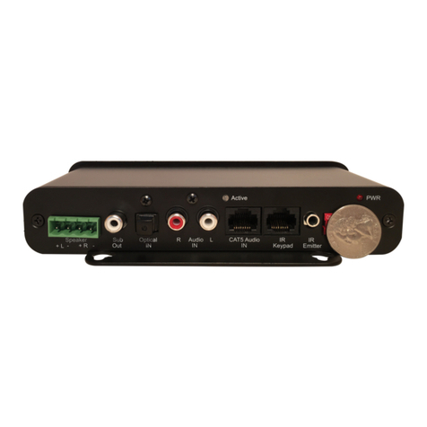
LED Indications:
PWR LED: LED ON indicates Power to the amplifier is ON
Active LED: Red indicates no audio input - Amplifier is in standby.
Green indicates audio input is present.
Volume Control works only when this LED is green.
Specifications:
Power input: 24VDC, 2.5 amp, earth ground negative, 3 plug
UL approved transformer
Audio Output: 100 Watts/ 50 Watts x2
OHMS 8 ohms @ <1% THD
Frequency Response: 20-20kHz (+/-3dB)
Signal to Noise Ratio: >85dB
Subwoofer output frequency 20-80 Hz
Input Sensitivity: 50 mV RMS
Operating temperature: -8 ~ +130º C
Specifications subject to change without notice
Stripping and Connecting CAT5 Wire
Blade
CAT5
1. Place the CAT5 between the blade and the first notch of the J-110 tool.
CAT5 cable should be stripped with a proper stripping tool, such as Channel
Vision’s J-110 tool.
Slight
pressure
Rotate
1 turn only
2. Rotate the tool only once. Multiple
turns could damage the inner wires.
3. Inspect the inner wires for damage.
If any wires are cut start over at step 1.
Check for damage
Green/White - Left channel ground
Green - Left channel
Orange/White - Right channel ground
Blue - Signal
Blue/White
Orange - Right channel
Brown/White - Ground
Brown - 24V DC for A0125 power
TIA-568A RJ-45 Modular Plug for Audio Input Connector
Side view:
Top view:
A0127 or A0129 keypad
A4623
Rear
Pin 7: Ground
Pin 8: +VDC
Pin 4: IR signal
Pin 8: +VDC
Pin 7: Ground
Pin 4: IR signal
N.C.
Pin 8: +VDC
Pin 7: Ground
Pin 4: IR signal
Green/White
Green
Orange/White
Pin 4 Blue - IR Signal
Blue/White
Orange -
Pin 7 Brown/White - Ground
Pin 8 Brown - 12VDC
TIA-568A RJ-45 Modular Plug for IR Keypad or IR-2400 Input Connector
Side view:
Top view:
500-412 Rev. G
www.channelvisi o n . c o m
!This equipment generates, uses and can radiate radio frequency energy
and, if not installed and used in accordance with the instructions, may
cause harmful interference to radio communications. However, there is no
guarantee that interference will not occur in a particular installation. If this
equipment does cause harmful interference to radio or television
reception, which can be determined by turning the equipment off and on,
the user is encouraged to try to correct the interference by one or more of
the following measures
Reorient or relocate the receiving antenna.
Increase the separation between the equipment and receiver.
Connect the equipment into an outlet on a circuit different from that to
which the receiver is connected. Consult the dealer or an experienced
radio/TV technician for help. Modifications not expressly approved by the
manufacturer could void the user's authority to operated the equipment
under FCC rules.
FOR HOME OR OFFICE USE
Channel Vision A0360
Tested To Comply
With FCC Standards
In the unlikely event you require the 1 year warranty service, Channel Vision Technology will
repair or replace any defect in material or workmanship which occurs during normal use of this
product with new or rebuilt parts, free of charge in the USA, for one year from the date of
original purchase.
Please refer to our complete warranty details at http://www.channelvision.com/warranty/
Note: This equipment has been tested and found to comply with the limits
for a Class B digital device, pursuant to part 15 of the FCC Rules. These
limits are designed to provide reasonable protection against harmful
interference in a residential installation.
714/424-6500 [email protected]

Other manuals for A0360

1

Other Channel Vision Amplifier manuals

Channel Vision A-BUS AB-202 User manual

Channel Vision

Channel Vision A-BUS AB-202 User manual

Channel Vision Audio/Video Distribution Amplifier VDA-12 User manual

Channel Vision

Channel Vision Audio/Video Distribution Amplifier VDA-12 User manual

Channel Vision A0362 User manual

Channel Vision

Channel Vision A0362 User manual

Channel Vision C-0310 User manual

Channel Vision

Channel Vision C-0310 User manual

Channel Vision CVT-38BID User manual

Channel Vision

Channel Vision CVT-38BID User manual

Channel Vision Central C-0315 User manual
Channel Vision

Channel Vision Central C-0315 User manual

Channel Vision A500 User manual

Channel Vision

Channel Vision A500 User manual

Channel Vision A0240 User manual

Channel Vision

Channel Vision A0240 User manual

Channel Vision C-0314 User manual

Channel Vision

Channel Vision C-0314 User manual

Channel Vision A0360 User manual

Channel Vision

Channel Vision A0360 User manual

Channel Vision CVT-10 PIA User manual

Channel Vision

Channel Vision CVT-10 PIA User manual

Channel Vision ARIA A0361 User manual

Channel Vision

Channel Vision ARIA A0361 User manual

Channel Vision CVT-15PIA Manual

Channel Vision

Channel Vision CVT-15PIA Manual

Channel Vision CVT-15WB User manual

Channel Vision

Channel Vision CVT-15WB User manual

Channel Vision Aria A1260 User manual

Channel Vision

Channel Vision Aria A1260 User manual

Channel Vision A0240 User manual

Channel Vision

Channel Vision A0240 User manual
Channel Vision Aria A0350 User manual

Channel Vision

Channel Vision Aria A0350 User manual
Channel Vision A0240 User manual

Channel Vision

Channel Vision A0240 User manual

Channel Vision A0240 User manual

Channel Vision

Channel Vision A0240 User manual

Channel Vision A0240 User manual

Channel Vision

Channel Vision A0240 User manual

Channel Vision ARIA A4623 User manual

Channel Vision

Channel Vision ARIA A4623 User manual

Channel Vision VDA-12 User manual

Channel Vision

Channel Vision VDA-12 User manual

Channel Vision P-2014 User manual

Channel Vision

Channel Vision P-2014 User manual

Channel Vision Aria A0350 User manual

Channel Vision

Channel Vision Aria A0350 User manual

Popular Amplifier manuals by other brands

zBoost YXC-40K Installation overview

zBoost

zBoost YXC-40K Installation overview

cahors CAP5510 instructions

cahors

cahors CAP5510 instructions

Williams Sound DL102 Quick setup

Williams Sound

Williams Sound DL102 Quick setup

JBL BP600.1 Service manual

JBL

JBL BP600.1 Service manual

Channel Plus CHANNELPLUS MDS-6 owner's manual

Channel Plus

Channel Plus CHANNELPLUS MDS-6 owner's manual

ICON NeoAmp owner's manual

ICON

ICON NeoAmp owner's manual

AVM OVATION PH 8.3 operating instructions

AVM

AVM OVATION PH 8.3 operating instructions

ISC 9T97A250 user manual

ISC

ISC 9T97A250 user manual

DaytonAudio DTA-PRO user manual

DaytonAudio

DaytonAudio DTA-PRO user manual

Paul C. Buff Vagabond II quick start guide

Paul C. Buff

Paul C. Buff Vagabond II quick start guide

Marshall Amplification 1974X quick start guide

Marshall Amplification

Marshall Amplification 1974X quick start guide

Harman Kardon HK6800 Technical manual

Harman Kardon

Harman Kardon HK6800 Technical manual

Prolude Amplification D750 The Little Brick user manual

Prolude Amplification

Prolude Amplification D750 The Little Brick user manual

Behringer V-AMPIRE LX110 user manual

Behringer

Behringer V-AMPIRE LX110 user manual

Martin Roland MA-3800HD Operation manual

Martin Roland

Martin Roland MA-3800HD Operation manual

THÖRESS Full Function Integrated "Super"... instruction manual

THÖRESS

THÖRESS Full Function Integrated "Super"... instruction manual

Fosi Audio M03 user manual

Fosi Audio

Fosi Audio M03 user manual

JBL VMA160 Operation manual

JBL

JBL VMA160 Operation manual

manuals.online logo
manuals.online logoBrands
  • About & Mission
  • Contact us
  • Privacy Policy
  • Terms and Conditions

Copyright 2025 Manuals.Online. All Rights Reserved.