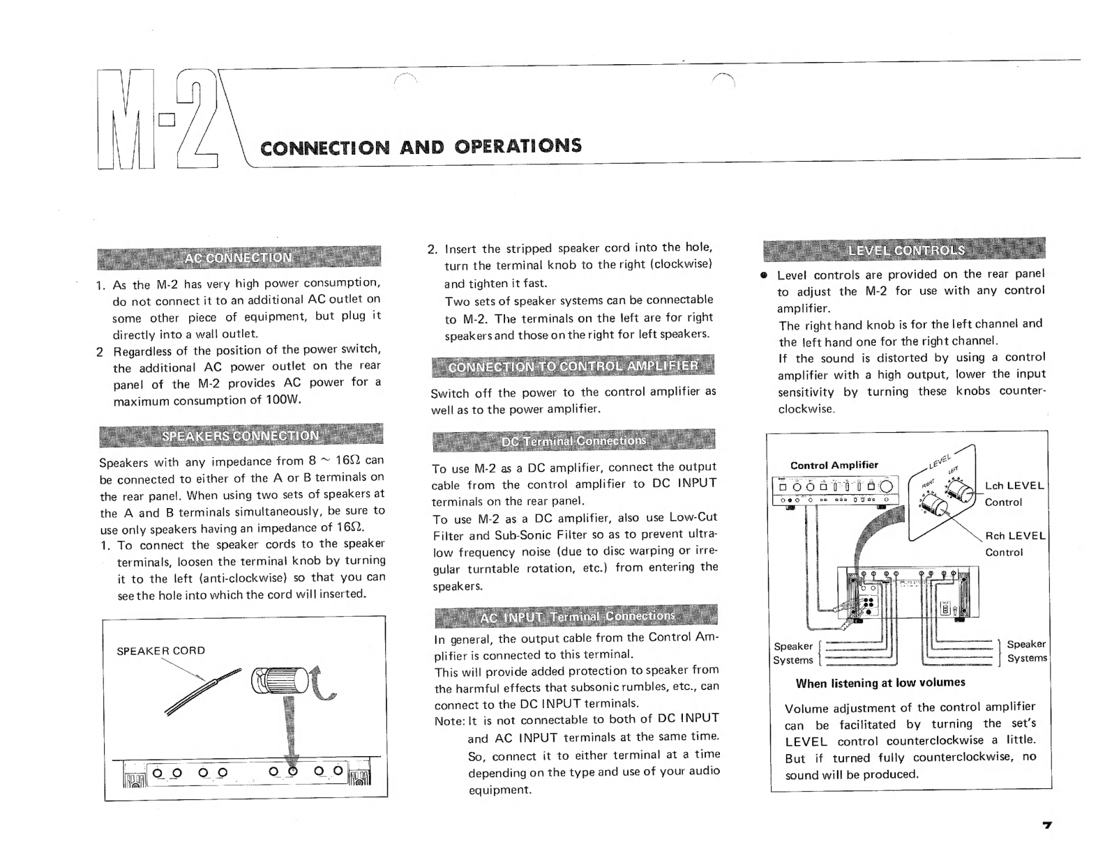
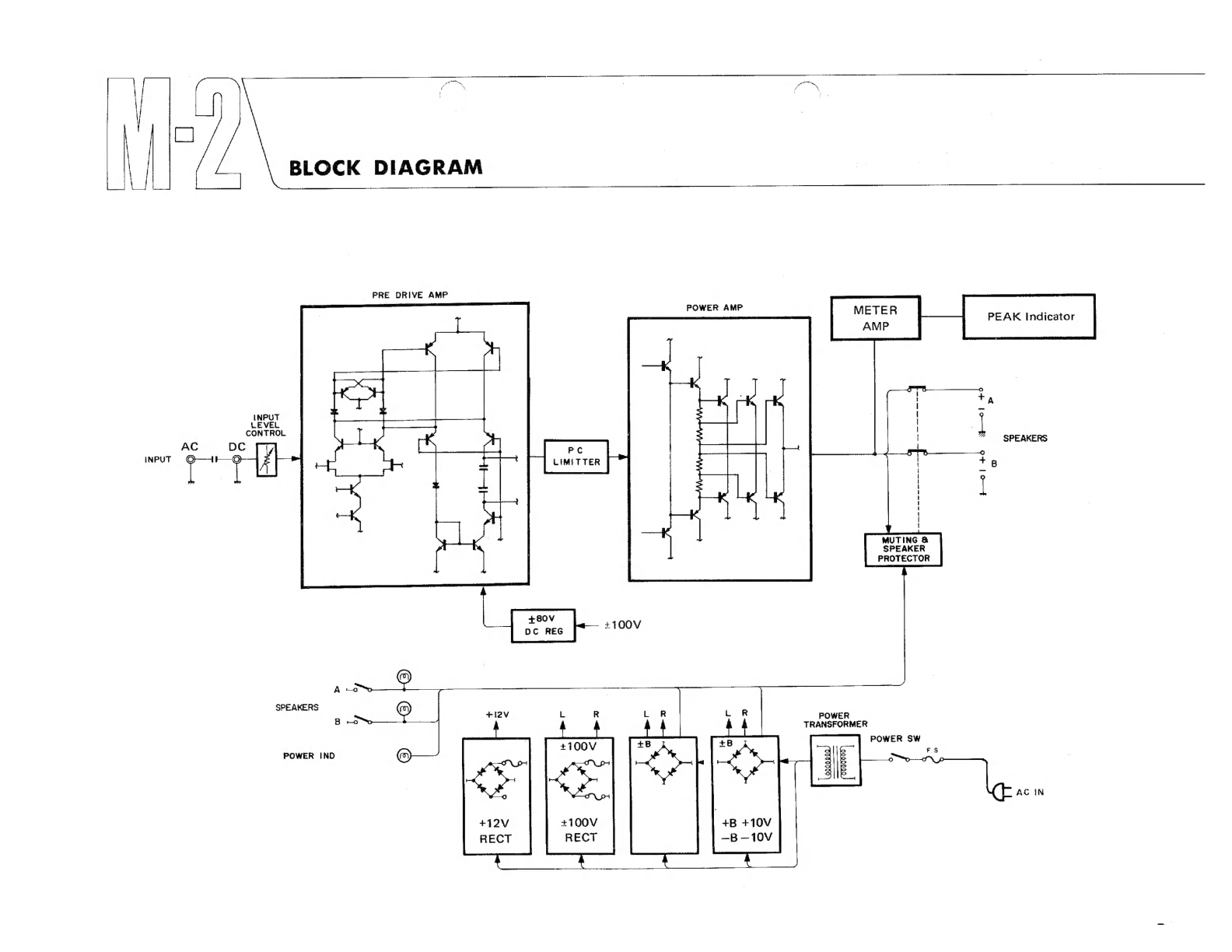
Yamaha M-2 User manual

Pg
ti
H
6
DDE:
রে
a
-
at; x
E
or
188
א
8
us
DDOZ
002
DA
2
>
RG
mor
]8
8
₪
8 ₪
8
8
8
8
E)
=
Hi.
RA
Ea

Thank
you
very
much
for
purchasing
the
YAMAHA
Stereo
Power
Amplifier
M-2
Developed
CONTENTS
by
applying
the
best
of
YAMAHA’s
superior
electronic
technology,
the
M-2
is
a
DC
stereo
power
amplifier
that
achieves
an
extremely
high
level
of
performance.
OR
>
The
output
stage,
which
uses
pure
complementary
OCL
and
triple
push-pull
circuitry,
Caution:
Read.
This
Before
Operating
produces
the
rated
output
of
240W
+
240W
without
any
strain
on
the
large-capacity
power
Your
M2...
RE
3
supply
section,
ee
ÍConnection
Diagram.
EO
4
Before
first
operating
your
M-2,
please
read
this
Owner's
Manual
carefully,
in
order
to
0011...
[Front
Panel
and
GT
`
6
realize
the
potential
of
the
unit
and
to
keep
it
in
best
condition
for
many
years
of
trouble-
^ ^
[Connection
and
Operation
.|...........
7
free
use.
Specifications
|...
.................
8
Block
Diagram
s
er
rU
Or
Ci
EC
EO
Eg
9
Schematic
Diagram
|
.................
10
Troubleshooting
|..........
eren
11
€
The
voltage
amplifying
stage
employs
a
cascade-
€
Two
extremely
large
22,000
uF
capacitors,
two
connected
differential
two-stage
circuit
separate
constant-voltage
power
supplies
for
the
throughout.
The
use
of
a
Dual
FET
input
and
a
cascode
bootstrap
circuit
in
the
first
stage
and
a
cas-
cade-connection,
current
mirror
and
push-pull
output
in
the
pre-drive
stage
ensures
a
high
degree
of
stability,
low
distortion
and
im-
proved
high-frequency
characteristics.
In
the
driver
and
the
power
amplifier
a
three-
stage
emitter
follower
is
pure
complementary
OCL
SEPP
circuitry
using
high-ft
transistors.
This
accounts
for
wide
bandwidth,
high
output
and low
distortion.
voltage
amplifying
stage,
and
the
use
of
a
pure
copper
plate
earth
line
for
ultra-low
impedance
guarantee
greatly
reduced
intermodulation
dis-
tortion,
improved
separation
and
absolutely
stable
operation.
Other
Features
Except
for
the
chemical
capacitors
in
the
power
supply
section,
mylar
and
styrol
capacitors
are
employed
throughout.
Layout
of
parts,
wiring,
earth
line
as
well
as
many
other
aspects
have
been
given
due
con-
sideration.
The
basic
design
ensures
high
reliability,
while
the
ultimate
aim
has
been
the
improvement
of
the
overall
audio
characteristics.
IMPORTANT!
Please
record
the
serial
number
of
your
unit
in
the
space
below
Model
Name
M-2
Serial
No.
The
serial
number
is
located
on
the
rear
of
the
chassis.
Retain
this
Owner's
Manual
in
a
safe
place
for
future
reference.

PLACE
OF
INSTALLATION
Do
not
use
the
set
in
€
locations
exposed
to
direct
sunshine,
such
as
near
windows
®
locations
of
high
temperatures,
such
as
near
heaters
€
locations
of
extremely
low
temperatures
©
humid
or
dusty
locations
e
Since
the
M-2
is
quite
heavy
[20.9
kgl
it
should
be
placed
on
a
firm
base.
'
WATER
DAMAGE
If
with
water,
immediately
disconnect
the
power
plug
and
contact
your
YAMAHA
service
store.
Be
careful
not
to
place
any
container
that
holds
liguid
near
the
ampli-
fier.
PROPER
VENTILATION
Never
cover
the
ventilation
holes
on
top
of
the
amplifier
with
any
object.
If
proper
ventilation
is
not
ensured,
the
internal
tem-
perature
of
the
set
will
rise
unduly,
which
will
cause
improper
operation
and
lead
to
damage.
,
CAREFUL
HANDLING
Avoid
using
strong
force
when
operating
any
of
the
switches
and
controls.
|
UNAUTHORIZED
OPENING
an
Never
open
the
case
of
the
amplifier
or
touch
any
of
the
parts
inside,
as
there
is
serious
danger
of
electric
shock.
If,
by
accident,
some
foreign
matter
has
been
dropped
inside
the
set,
immediately
disconnect
the
power
plug
and
contact
your
YAMAHA
service
store.
`
ADDITIONAL
AC
POWER
OUTLET
The
additional
AC
power
outlet
on
the
rear
panel
of
the
set
is
UNSWITCHED
(not
linked
with
the
power
switch)
and
has
a
maximum
capacity
of
100W.
Before
con-
necting
another
piece
of
equipment
to
this
outlet,
check
its
power
consumption
to
ensure
it
does
not
exceed
this
limit.
MOVING
THE
SET
Before
moving
the
amplifier,
be
sure
to
dis-
connect
the
power
plug
as
well
as
all
other
connection
cords.
POWER
CORD
When
disconnecting
the
power
cord,
always
hold
the
plug
itself
and
do
not
pull
the
cord.
When
the
set
is
not
to
be
used
for
a
long
period
of
time,
it
is
recommended
to
dis-
connect
the
power
cord.
PLAYING
RECORDS
Be
sure
to
turn
down
the
volume
on
the
contro!
amplifier
before
lifting
or
lowering
the
tone
arm
when
playing
records.
Other-
wise
the
transient
noise
may
cause
damage
to
the
speakers.
MAKING
CONNECTIONS
Always
switch
off
the
power
before
connect-
ing
or
disconnecting
the
input
cables.
CLEANING
Avoid
wiping
the
case
with
liquids
such
as
benzine
or
thinner,
and
do
not
use
insecti-
cide
sprays
or
the
like
near
the
set.
Always
use
a
soft,
dry
cloth
to
wipe
the
set.
—
BEFORE
REQUESTING
SERVICE
Before
calling
in
a
service
technician,
please
check
the
TROUBLESHOOTING
chart
in
the
last
section
of
this
manual
to
be
sure
there
is
no
misoperation.
OWNER’S
MANUAL
Please
keep
this
Owner’s
Manual
for
future
reference.

RIGHT
Speakers
CONNECTION
DIAGRAM
Ground
cord
Control
Amplifier
Gb
YAMAHA
eS
אתה
ג
PREVENT
FIRE
CH
SHOCK
৮5289)
DD
AOT
EXPOSE
THIS
o
AC
QUTLETS
120
5آانالا
SOWATTS
ALLAR
TO
RAIN
OR
MOISTURE
E
:
60145
CAUTION:
OG
NOT
REMOVE
THESE
SCREWS.
SCC
DDT”OV
CAUTION
HAN
AM
ATSU.
JAPAN
ATTENTION:
NE.
PAS
ENLLVER
LES
VIS
LIFE
LES
INSTRUCTIONS.
AU-
DESSOUS
DE
LAPPASEIL
—
TARE
גו
Pit
AEC
UT,
2
Ux
TOME
vci
Ae
MAR
Jiu)
AAR
TOTAL
m
2১:
If
DC
voltage
is
contained
in
the
output
of
a
control
amplifier
connected
to
the
DC
INPUT
terminals,
the
protect
circuit
operates,
ACRE
8
8
/SPEA«ER
৬৯6
e
১০
SPEAKER
SPEAKER
WARNING-TO
PREVENT
FIRE
OR
SHOCK
HAZARI
NOT
EXPOSE
THIS
APPLIANCE
TO
RAIN
OR
MOI.
CAUTION-DO
NOT
REMOVE
THESE
SCREWS.
SEE

e
Canadian
Model
DEE
EE
LEFT
Speakers

FRONT
PANEL
AND
CONTROLS
9
NATURAL
5
SIEREQ
POWER
p^
₪5
P
ER
GO
POWER“
switch)
When
this
button
is
depressed,
power
to
the
unit
will
be
switched
on
and
the
switch
will
light
up.
When
depressed
again,
power
is
turned
off.
₪
Due
to
the
action
of
the
muting
relay,
no
sound
will
be
heard
for
several
seconds
after
switching
on
the
power.
This
prevents
any
transient
switching
noises
from
reaching
the
speakers.
W
Be
sure
to
turn
down
the
VOLUME
control
on
the
control
amplifier
to
minimum
before
turning
on
the
POWER
switch
to
guard
the
speakers
against
any
sudden
loud
program
sounds
produced
after
the
muting
relay
time.
am
mm
enne
DU
HN
1
SPEAKER
PEAK
OUTPUT
LEVEL
O
SPEAKERSI(A
and
B)
These
two
push-button
switches
govern
the
two
speaker
terminals
A
and
B.
When
depressed,
the
speaker
set
connected
to
the
respective
terminal
will
be
connected
and
the
switch
will
light
up.
Depressing
the
switch
again
will
disconnect
the
speakers.
When
using
both
terminals
at
the
same
time,
refer
to
"Speaker
Connections"
(p.
7)
regarding
speaker
impedance.
The
SPEAKER
switches
should
be
turned
off
when
changing
the
connection
of
the
speaker
cords,
and
they
can
be
used
in
other
cases,
such
as
changing
program
sources
etc.,
as
well.
D.
ווווווווווווווווון..
הפשה
400
৩”
101000010000000000,
0
@
PEAK
OUTPUT
LEVEL
(PEAK
and
OVERLOAD
INDICATOR)
These
peak
indicators
provide
visual
indication
of
the
left
and
right
output
levels.
They
cover
a
range
of
0.002W
to
400W
(89)
(—50dB
to
3dB).
Note:
Also
that
the
meters
are
calibrated
accu-
rately
for
output
power
into
standard
2
speakers,
but
that
corrections
must
be
applied
if
speakers
with
different
imped-
ance
are
used.
Clipping
(at
about
2%
THD)
is
indicated
for
the
left
and
right
outputs
separately
by
the
OVER-
LOAD
indicators.
When
these
light
up,
turn
down
the
input
level
by
using
the
LEVEL
controls
on
the
rear
panel.

CONNECTION
AND
|
AC
CONNECTIC
1.
As
the
M-2
has
very
high
power
consumption,
do
not
connect
it
to
an
additional
AC
outlet
on
some
other
piece
of
equipment,
but
plug
it
directly
into
a
wall
outlet.
2
Regardless
of
the
position
of
the
power
switch,
the
additional
AC
power
outlet
on
the
rear
panel
of
the
M-2
provides
AC
power
for
a
maximum
consumption
of
100W.
8
5
=
S
0
t
7]
6
H
Speakers
with
any
impedance
from
8
~
1682
can
be
connected
to
either
of
the
A
or
B
terminals
on
the
rear
panel.
When
using
two
sets
of
speakers
at
the
A
and
B
terminals
simultaneously,
be
sure
to
use
only
speakers
having
an
impedance
of
4.
1.
To
connect
the
speaker
cords
to
the
speaker
terminals,
loosen
the
terminal
knob
by
turning
it
to
the
left
(anti-clockwise)
so
that
you
can
see
the
hole
into
which
the
cord
will
inserted.
SPEAKER
CORD
ho
OPERATIONS
2.
Insert
the
stripped
speaker
cord
into
the
hole,
turn
the
terminal
knob
to
the
right
(clockwise)
and
tighten
it
fast.
Two
sets
of
speaker
systems
can
be
connectable
to
M-2.
The
terminals
on
the
left
are
for
right
speakers
and
those
on
the
right
for
left
speakers.
'
CONNECTION
TO
CONTROL
AMPLIFIER
Switch
off
the
power
to
the
control
amplifier
as
well
as
to
the
power
amplifier.
To
use
M-2
as
a
DC
amplifier,
connect
the
output
cable
from
the
control
amplifier
to
DC
INPUT
terminals
on
the
rear
panel.
To
use
M-2
as
a
DC
amplifier,
also
use
Low-Cut
Filter
and
Sub-Sonic
Filter
so
as
to
prevent
ultra-
low
frequency
noise
(due
to
disc
warping
or
irre-
gular
turntable
rotation,
etc.)
from
entering
the
speakers.
In
general,
the
output
cable
from
the
Control
Am-
plifier
is
connected
to
this
terminal.
This
will
provide
added
protection
to
speaker
from
the
harmful
effects
that
subsonic
rumbles,
etc.,
can
connect
to
the
DC
INPUT
terminals.
Note:
It
is
not
connectable
to
both
of
DC
INPUT
and
AC
INPUT
terminals
at
the
same
time.
So,
connect
it
to
either
terminal
at
a
time
depending
on
the
type
and
use
of
your
audio
equipment.
כ
8
€
Level
controls
are
provided
on
the
rear
panel
to
adjust
the
M-2
for
use
with
any
control
amplifier.
The
right
hand
knob
is
for
the
left
channel
and
the
left
hand
one
for
the
right
channel.
If
the
sound
is
distorted
by
using
a
contro!
amplifier
with
a
high
output,
lower
the
input
sensitivity
by
turning
these
knobs
counter-
clockwise.
Control
Amplifier
80
66
ם
o
o
০
EU
ean
0
0০5
D
Lch
LEVEL
Control
Rch
LEVEL
Control
Speaker
|
(|
7)
Speaker
Speaker
is
Systems
When
listening
at
low
volumes
Volume
adjustment
of
the
control
amplifier
can
be
facilitated
by
turning
the
set's
LEVEL
control
counterclockwise
a
little.
But
if
turned
fully
counterclockwise,
no
sound
will
be
produced.

SPECIFICATIONS
Rated
Output
Power.
|
|
240W
+
240W
(82,
20Hz~
30kHz
0.005%
T.H.D)
11
01727
1
90172
|
(80,
120W,
0.0196
T.H.D)
-
Input
Sensitivity/
Impedance
০
775
החדהה
שש
-
নে
E
Kênanga
-
||
DC
Input
|
00018111110
—
שש
רה
7
המשר
শিট
|
100072
:
-—0.7:0.5dB
-
Reina
Rw
—
der
T
eee
——
কে
—
Harmonic
Distortion
||
ו
PARANI
اذل«
০০৯৭
Less
than
0.004%
(1
O0kHz,
120W)
1B,
50Hz:7kHz=4:1,
BOW)
Channel
Separation
(LR,
R
>
L)
I
HYR
2১১
AYAM
A
AAN
A
শিপ
টিপি
লীনা?
Peak
Indicator
ווה
indicator
Point
;
UN
GE
Ae
eg
Malak
ag
YY,
Indicator
Level
EE
IHE
ELE
un
sam
DË
meer,
Rated
Power
Consumption
=
ee
-—
————
..
Canadian
Medel
1800
vA
וו
AC
AC
Outlet
—
.
Di
mensions
—
—
—
^
I
EE
LS
Weight
DEENEN
Y
TAU
a
rn
Specifications
subject
to
change
without
notice.

BLOCK
DIAGRAM
PRE
DRIVE
AMP
CONTROL
AC
DC
INPUT
וו
Hol
+
yO)
+
POWER
AMP
METER
PEAK
Indicator
AMP
A
*
SPEAKERS
MM
T
1
₪
MUTING
8
SPEAKER
PROTECTOR
POWER
TRANSFORMER
POWER
SW
E
1
FS
:
|
AC
IN
SPEAKERS
POWER
IND
+B
+10V
—B
—10V

DON
HRA
A
fiser
‘in
rut
2}
ac
ec
le
d
:
HR
(eb
rt
910১
DDR
ne
taas
WIéCHp
258
EH
ICA
m-
EE
ae
1052
₪
5
At
©
UU
88507)
28:18
?וז
Sp
ES
3
11858),
meet:
my
(22083
El
A
17105
KSC
i 1
|
:
|
j
וו
tni
ו
5
3
Leck
dE
t.
11
5
5
“
2
SC
1
gos
i
rs
"e
;
רו
HOLE
ww
^
CD
EI
cu
1
:
1
1
Eines
ww
m
Tie
5
1
78619531815
WN?
?
Y
,
FS
|
m
dd
:
dà
4
-
,
1৯531]
repo"
Uta
TEM
mE
25097457505)
pake
LT)
d
2
1
ys
WIL
2.001001,
|
PA
53১৮
=
e
{>
RESISTOS
d
dk
4
j
|
RESI
-a
dian
Since
mist
ee
উড
ema
"METRLUED.
OEÍBAFÍON
RESISTOR
8
ששם
|
META
এ
18084
=
"KI
TD
,
امام
انم
يلا
SEI
vi
ABD
A
aM
O
f
5
=
AD
—
Wm.
"er
ei
[08
a
8
n
:
₪
WD
w
CAPACITOR
`
0
>
Oe
\
PLS
St
"tu
৯5১
Ge
a 5
(18627
FEMASES
|
ES
up
5
וזב
KO
WAEK|
או
E
à
:
3
1১:
4
i
|
"o
|
5215132116
g :
;
; |
"
a
|
SCHEMATIC
DIAGRAM
|
ב
canem
,
וו
וו
רו
רו
hene
Mr
acne
+
HER
OT
2557
E
KEC
50.0
0043-1
4
Mat
aa

TROUBLESHOOTING
০০৮৪০
ו
ge
NM
pepe
J————Ó
i
Symptom
Cause
Een,
Ap.
sê
inan
AN
GB
EE
|
Power
wiil
not
turn
on
although
POWER
switch
is
ON.
;
Power
cord
plug
is
not
firmly
inserted
into
AC
outlet.
Power
does
not
turn
on
when
power
plug
is
inserted
into
AC
outlet.
Contact
an
audio
serviceman
at
your
nearest
YAMAHA
EE
No
sound
produced
from
the
right
and
left
speakers,
or
|
|
Insufficient
connection
between
control
amplifier
and
Check
and
confirm
connection,
or
operation.
|
either
the
right,
or
left
speaker,
|
power
amplifier,
or
between
power
amplifier
and
speak-
|
|
|
ers.
|
|
|
|
a
a,
:
EE
ובנ
geen
e
aa
|
ae
م
יוו
০১০৯৭
eg
| |
|
BALANCE
control
of
the
control
amplifier
has
deviated
|
Properly
re-adjust
BALANCE
control
of
control
ampli-
|
|
either
to
the
right,
or
left
side.
|
fier.
|
|
M
——
MÀ
M
M
m
M
—
M
M
—
ا
TV
RUE
SE
EYN
Em
5
e
|
|
LEVEL
control
turned
down
too
much
(Turned
too
far
|
Turn
LEVEL
control
clockwise.
|
|
counterclockwise}.
|
|
Beete
EE
ant
tenn
—
1
|
||
|
Sounds
suddenly
cease
during
PLAY.
Speaker's
protective
circuit
is
working
because
a
DC
po-
When
the
potential
of
the
power
DN
becomes
zero,
|
|
tential
more
than
+
1V
has
generated
at
the
speaker's
|
the
relay
will
be
actuated,
causing
the
circuit
to
be
|
|
output
terminal,
|
connected.
N
|
|
Turn
off
the
POWER
switch
of
the
power
amplifier,
|
|
Wait
a
little
while
and
turn
it
on
again.
|
23000000000
—
Ls
2
NN
NEF
|
baen
alit
inside
the
circuit.
Contact
an
audio
serviceman
at
your
nearest
YAMAHA
|
|
dealer.
p
s
NES
"—
MEM
MEMO
100000000102121
0530
TEN
el
ורוו
יוור
ור
Y
للد
|
Unnatural
reproduced
sounds
with
poor
bass
and
unstable
The
phases
(+
and
—}
of
the
power
amplifier
not
match-
After
matching
the
phases
properly,
re-connect.
|
|
stereo
image.
ing
those
of
the
speakers.
|
|
rrr
[M
Eu
a
EEN
SE
|
Sufficient
volume
not
obtained
when
VOLUME
control
Input
LEVEL
control
is
turned
counterclockwise.
Adjust
to
proper
volume
by
turning
input
LEVEL
=
|
of
control
amplifier
is
turned
up.
;
trol
clockwise,
|
i
[prre
| |
|
=
;
Loud
humming
generated
during
program
audition.
Insufficient
contact
af
pin
plug.
Re-insert
pin
E
in
firm
manner.
H
;
HD
Sha
E
בב
تك
SCE
SEE
PN
E
ו
لج
Sateen
a
a
AE
E
E
N
p
PM
২০০
5
|
Earth
line
of
8
not
connected
to
GND
terminal
টা,
earth
line
to
GND
terminal
of
control
দা
Vier.
of
control
amplifier.

SINCE
1887
NIPPON
GAKKI
CO.,
LTD.
HAMAMATSU,
JAPAN
Other manuals for M-2
3
Table of contents
Other Yamaha Amplifier manuals

Yamaha
Yamaha MA2120 User manual

Yamaha
Yamaha T4n User manual

Yamaha
Yamaha MX-D1 - Amplifier User manual

Yamaha
Yamaha MX-55 User manual

Yamaha
Yamaha P2040 User manual

Yamaha
Yamaha M-70 User manual

Yamaha
Yamaha C-45 User manual

Yamaha
Yamaha P2160 User manual

Yamaha
Yamaha M-40 User manual

Yamaha
Yamaha Portatone PSR A1000 User manual

Yamaha
Yamaha AX-397 User manual

Yamaha
Yamaha KA-30 User manual

Yamaha
Yamaha DSP-E800 User manual

Yamaha
Yamaha A-S2000 - Amplifier User manual

Yamaha
Yamaha MA2030 User manual

Yamaha
Yamaha MX-800 User manual

Yamaha
Yamaha MX-70 User manual

Yamaha
Yamaha A-S2100 User manual

Yamaha
Yamaha MA2030 User manual

Yamaha
Yamaha XMV8130-D User manual