Octave V 110 SE User manual

V110SE
Owner's Manual
English

3
INTRODUCTION
Congratulations and thank you for choosing OCTAVE
V 110 SE
You are now the owner of one of the world's most innovative and reliable amplifiers. Look
after it, and it will provide you many years of listening pleasure.
You often hear people claim that tube amplifier design has not progressed for years. The
operating principles of tubes have indeed been documented extensively and are well
known to amplifier designers. Of course, the same can be said for transistor amplifiers.
However, advances in both technologies are still possible thanks to the development of
innovative and improved components, our greater appreciation of the fundamental
principles and, of course, deeper and more advanced insights into the interaction of
amplifier and loudspeaker. With tube amplifiers in particular, a general reluctance to
depart from the classic circuit designs has not done the technology any favors. Although
today's loudspeakers and source equipment provide better performance than ever before,
they also present greater demands on amplifiers. Modern sound reproduction equipment
delivers a level of performance at a price that simply would not have been possible 20 or
even 10 years ago.
These advances have been achieved through the application of the latest technological
developments as they become available and affordable. OCTAVE has specialized in tube
amplification for the past 30 years, during which time we have developed a number of
innovative technologies that have earned us a reputation as one of the leaders in the
field.
Here's wishing you many happy hours of musical pleasure!
Andreas Hofmann

4

5
CONTENTS
Page
Introduction ................................................................................................. 3
1 Description of the V 110 SE ......................................................................... 7
2 Safety instructions ....................................................................................... 8
2.1 Before you begin .......................................................................................... 8
2.2 Placement .................................................................................................... 9
2.3 Warranty ....................................................................................................... 9
3 Getting started .............................................................................................. 10
3.1 Unpacking, package contents ...................................................................... 10
3.2 Removing the grille ...................................................................................... 10
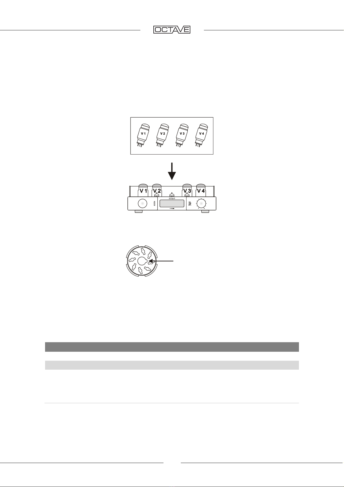
3.3 Installing the power tubes ............................................................................ 11
3.4 Switching on for the first time: the soft-start feature .................................... 11
3.5 Checking the tubes (BIAS) ........................................................................... 12
3.6 Connecting other components ..................................................................... 12
3.7 Connection options: overview ...................................................................... 13
4 Front panel controls ..................................................................................... 14
5 Rear panel connections ............................................................................... 16
6 Advanced functions and connection options ................................................ 18
6.1 Power Selector, alternative output tubes ..................................................... 18
6.2 Changing the damping factor ....................................................................... 19
6.2. Protection ..................................................................................................... 20
6.3 Soft-Start ...................................................................................................... 20
6.4 Ecomode ...................................................................................................... 22
6.5 Front Channel ............................................................................................. 22
6.6 Pre-Out regulated ........................................................................................ 22
6.6.1 Using with an active subwoofer ................................................................... 22
6.6.2 Using in bi-amped systems .......................................................................... 22
7 Tubes ........................................................................................................... 23
7.1 Removing the grille (see 3.2) ....................................................................... 23
7.2 Tube layout .................................................................................................. 23
7.3 BIAS Measurement System ......................................................................... 24
7.4 Replacing the tubes ..................................................................................... 26
7.5 Running in the tubes .................................................................................... 26
7.6 Tube Service Life ......................................................................................... 26
8 Remote Control ............................................................................................ 27
9 Optional Phono - MC/MM ............................................................................. 27
10 Using Black Box or Super Black Box ........................................................... 28
10.1 The Black Box option ................................................................................... 28
10.2 The Super Black Box option ........................................................................ 29
11 Troubleshooting ........................................................................................... 30
11.1 Faults caused by external issues ................................................................. 30
11.2 Faults caused by tubes ................................................................................ 32
12 Specifications and Dimensions .................................................................... 34
13 Frequently Asked Questions (FAQ) ............................................................. 38

6

7
1. DESCRIPTION OF THE V 110 SE
Following the phenomenal international success of the flagship Octave V 80 SE integrated
amplifier, it was logical for the company to utilize the Octave Dynamic Technologies (ODT) in the
further development of the popular V 110 model. The ODT concepts were first realized in the
Jubilee Mono SE, and subsequently incorporated into the MRE 220 mono power amplifier. The
performance of the MRE 220 benefited tremendously from the new technologies, which Octave
next implemented into its integrated amplifier range by also featuring ODT in the new V 80 SE.
Now, the next most powerful integrated amplifier of the Octave model range benefits from the many
years of experience and continuous development as the V 110 model goes into its second stage of
evolution. After all, the V 110 SE not only comes with the new Octave Dynamic Technology (ODT),
but it also offers even the unique opportunity of a "damping factor tuning". (See chap. 6.2.)
ODT Electronic
Essentially, looking to the technical aspects of ODT it is all about very high dynamic output power.
Therefore the newly developed KT 120 or KT 150 power tubes are featured in these models.
Together with the revised power supply and new output transformers we practically achieve a
doubling of peak output power compared to conventional push-pull amplifiers. The driver stage,
which drives the output tubes while also monitoring them, is completely updated and comes a huge
step closer to the ideal of the push-pull principle. The much-misunderstood negative feedback does
its job extremely well without having any influence on the acoustic side. The new amplifier
generation impresses with extreme linearity, significantly increased stability and downright
negligible noise and hum. Therefore all the ODT equipped Octave models are even more
independent from the selected loudspeaker and always exhibit - unaffected by the load - the same
high performance level. The precise tonal balance is maintained even at extreme levels.
Special features of the V 110 SE
Power Pre Selector for alternate output tubes
The V 110 SE is a member of the family of amplifiers, based on the power tube KT 120. A switch
on the rear panel allows switching between different types of tubes, to ensure the operation in their
optimum sonic performance and working conditions.
Damping Factor Tuning
The new V 110 SE is the first model in the Octave range which offers another feature: the
capability to optimally mate the amplifier to any loudspeaker regardless of its design principle. The
damping factor of the V 110 SE can be set to three levels (LOW, MED and HIGH), allowing the
amp to thus achieve a more precise adjustment to the electrical load of the speaker than ever
before possible. This itself is unique in the world and, as always with Octave, simple to accomplish
Thanks to a specially developed circuit design for this application the different settings can be
easily realized by exchanging the input tube. Tubes with a different gain are used. The enormous
range of usable feedback makes this "amplification / attenuation factor" Tuning possible. Octave
supplies the V 110 SE with two additional input tubes to enable this fine tuning

8
2. SAFETY INSTRUCTIONS
2.1. Before you begin
Before using the V 110 SE for the first time, remove the grille and install the power tubes! (See
Section 3.2 „Removing the grille"). Replace the grille before switching the V 110 SE on.
Operating the amplifier without its protective grille is dangerous and not recommended.
In case of emergency: unplug the unit from the wall outlet
Never use an amplifier that is damaged or faulty. Make sure that no one can use it until it has been
repaired by a qualified service technician. Ensure that there is easy access to the IEC socket and
power cord.
Do not open the case
There are dangerously high voltages and hot tubes inside this equipment. To avoid a burn or the
risk of electric shock, never allow anyone except qualified personnel to open the case.
Servicing and maintenance
For reasons of safety, please ensure that any servicing, repairs or other modifications to OCTAVE
equipment are carried out only by a qualified technician. Always get an engineer to replace blown
fuses with ones of the same type and rating. If your amplifier requires servicing, please ship or take
your equipment directly to OCTAVE or to one of our authorized service centers.
Modifications to OCTAVE equipment
Use "audio grade" fuses and other power cables at your own risk. The use of such devices will void
the warranty. This also applies to the use contact fluids on the tube sockets.
Explanation of the warning symbols:
The lightning flash with arrowhead symbol within an equilateral triangle is
intended to alert the user to the presence of un-insulated, 'dangerous
voltages' within the product's enclosure that may be sufficient to constitute
a risk of electric shock to persons
The exclamation point within an equilateral triangle is intended to alert the
user to important operating and maintenance instructions
Before connecting up
Make sure that the voltage of your amplifier matches your electricity supply voltage.
Grounding
This amplifier is a protection class I device (with an earth conductor). To avoid the risk of electric
shock in the event of a fault, the unit must be grounded. To do this, use the power cable supplied
with the amplifier.

9
2. SAFETY INSTRUCTIONS
2.2. Placement
1. Location
OCTAVE equipment is designed strictly for use in a dry domestic environment. Do not use it in the
open air or in damp environments!
Never place plants or liquid-filled containers on your OCTAVE equipment. Take care to avoid
dropping objects or spilling liquids into the case. Should this happen, remove the mains plug
immediately and have your amplifier checked by a qualified service technician.
Condensation may form if the amplifier is taken from a cold environment into a warm one. If you do
this, wait until the amplifier has reached room temperature and is dry before switching it on.
Avoid installing the unit close to sources of heat such as radiators or anywhere that may be in
direct sunlight.
Do not operate the unit near flammable materials, gases or vapors. Avoid areas where there may
be heavy accumulations of dust or where the unit may be subject to mechanical vibration.
Place your OCTAVE amplifier on a stable, level surface.
2. Grille
Never operate the amplifier without the protective grille in place.
3. Ventilation
Make sure that your amplifier has an adequate flow of air around it. If you intend to install your
equipment into a cupboard or on a wall shelf unit, ensure that there is at least a ten centimeter (4
inch) gap between the ventilation slots and the walls all around the amplifier. The rear panel of
cupboards should have ventilation holes to prevent heat build-up. Do not rest the equipment on a
soft surface such as carpet or foam sheeting.
2.3. Warranty
OCTAVE can only guarantee the safety, reliability and performance of this unit if modifications and
repairs are carried out by specialized personnel and when the amplifier is operated in accordance
with the instructions contained in this manual.

10
3. GETTING STARTED
3.1. Unpack and check the contents of the box.
Scope of delivery
V 110 SE
1 set power tubes with tube layout diagram
2 pc driver tubes for modifying the damping factor
Power cord (3-core cable with 3-pin plug)
Remote control
2 screwdrivers: 1 x 2 mm flat-bladed screwdriver for adjusting the bias
1 x 2,5 mm Allen key for removing the cover
Owner's manual with warranty card
Cloth and gloves
3.2. Removing the grille
Procedure
For your own safety, make sure that the amplifier is not connected to power outlet
Completely remove the 4 hexagonal screws using the Allan key supplied. There are 2
screws on each side
Carefully pull the grille upward to remove

11
3. GETTING STARTED
3.3. Installing the power tubes
The power tubes are in a separate box in the tube compartment
Insert the power tubes into their sockets as shown on the tube layout. Ensure that you correctly
locate the anti-rotation lug on each of the tubes.
Anti-rotation recess
on the tube socket
3.4. Switching on for the first time – the Soft-Start feature
The V 110 SE is equipped with a multi-stage Soft-Start-Turn-On protection circuit which extends
component as well as tube life considerably by protecting against stress caused by typical high
inrush currents during switch on.
Procedure
Check that the Ecomode switch on the rear panel is in the "Eco off" position
Connect the V 110 SE to the mains. (On new units, this switch is set to "off" at the factory)
Switch on the V 110 SE using the amplifier’s mains power on/off switch.
Some LEDs will illuminate, depending on the position of the input rotary switch.
In any case the Power LED (indicates that the unit is switched on) and the Soft-Start LED
will be lit. The Soft-Start LED will extinguish a minute later once the unit has booted up.
The V 110 SE is now ready for work.

12
3. GETTING STARTED
3.5. Checking the power tubes – setting the BIAS
Turn the mode selector knob clockwise to position 6 = BIAS. The input LEDs will extinguish.
Five LEDs will now illuminate: The power LED and the 4 BIAS LEDs in the center of the display,
one for each power tube. If the amplifier is still cold, the LEDs will initially illuminate "yellow".
Please wait five to ten minutes.
Please don't turn the BIAS regulators until the Soft-Start-LED is extinguished.
(Because the tubes are still cold you would adjust the wrong BIAS)
After an additional 5 to 10 minutes, the BIAS control LEDs will change from yellow to green. This
indicates the correct bias and the unit is ready. If you notice any irregularity in the display please
refer to chapter 7.3.
3.6. Connecting other components to the V 110 SE
Procedure
Be sure to switch off the V 110 SE again!
Connect the other components in your system to the appropriate sockets on the rear of the
V 110 SE. (See chapter 5 "Rear panel connections". See also chapter 3.7. "Connection
options: overview")
Check that the switch positions on the front and rear of the amplifier are in their
recommended settings.
Switch on the V 110 SE using the on/off switch and wait until the Soft-Start LED
extinguishes. Now you can play music

13
3. GETTING STARTED
3.7. Connection options: overview

14
4. CONTROLS – the front panel
Legend
Power switch 0 = off; 1 = on. Power LED and Soft-Start LED illuminate. The Soft-Start
LED extinguishes after the start-up period of 50 seconds.
Input selector This is used to select the desired input signal. A blue LED indicates the
selected input on the display.
Pos 1: CD 1 RCA line level input for CD, SACD and similar
Pos 2: Tuner RCA line level input for tuner, etc.
Pos 3: Aux 1 RCA line level input for video, etc
Pos 4: Aux 2 RCA line level input for video, etc.
Pos 5: CD 2 XLR line level input for CD, SACD or similar
Pos 6: The electronic BIAS measurement system is
activated (see chap. 7.3).
Pos 7: Front Ch. Multichannel input. In this mode, the V 110 SE
functions as a two-channel power amplifier. The
volume control is bypassed. (See chap. 6.6)
The record output is switched off in this position
LED indicators Indicating the active input
Bias adjustment BIAS regulators and corresponding LED array for each power tube

15
4. CONTROLS – the front panel
Legend
BIAS adjustment BIAS regulators and corresponding LED array for each power tube
Remote control receiver To ensure optimum operation of the IR remote control, do not cover
this window
Status indicators Power Indicates that the unit is switched on.
Protection Red LED lights up when the electronic protection
system has switched off the amplifier in response to
an amplifier fault (see chapter 6.3.).
Soft-start Lights up during the soft-start process immediately
after switch-on. This LED extinguishes after about 1
minute when soft-start has been completed (see
chapter 6.4.).
Front Ch. Illuminates when multichannel-bypass function is
selected (see chapter 6.6.).
Volume control Remote controlled motorized potentiometer

16
6. CONNECTIONS – the rear panel
Legend
Ecomode
Eco off: Ecomode automatic is off.
Eco on: Ecomode automatic is on.
Amp off: The power stage of the amplifier is
off. (see chapter 6.5.).
CD 1 CD line level input, RCA
Tuner Tuner line level input, RCA
AUX 2 RCA line level input for Video etc. or MM/MC input with Phono option
AUX 1 RCA line level input for Video, etc
Tape Rec Record output for tape or DAT
GND Ground connector for Turntable.
Front Channel Input for the front channel of a multichannel receiver / DVD player
(see chapter 6.6).
Pre Out Regulated preamp output for active subwoofer, etc. (see chapter 6.7.).
CD 2 CD line level input, XLR with Pin configuration for XLR connectors
Power Selector Sliding switch to adjust the output power of the V 110 SE.
(see chapter 6.1)
E
como
d
e
Eco
o
ff
Eco
o
n
Am
p
o
ff

17
6. CONNECTIONS – the rear panel
Legend
CD 2 Pin configuration for XLR connectors (CD line level input,
XLR
Loudspeaker outputs Speaker connection terminals.
Red = positive terminal, Black = negative terminal.
The speaker negative terminal is connected to ground
(Super) Black Box
connection
The (Super) Black Box is an outboard power supply
capacitance upgrade for the power amplifier section (see
chapter 10).
You should switch off the V 110 SE using the power switch
before connecting and disconnecting the Black Box!
AC supply socket IEC socket with integrated fuse holder.
The fuse is located in a pullout compartment underneath
the socket. You can open the fuse compartment after
removing the mains plug.
Fuse For 230/240V: 4A slow-blow H (5 x 20 mm).
For 115/240V: 6.3A slow-blow H (5 x 20 mm).
For 100V: 6.3 A slow-blow H (5 x 20 mm).
Model identification plate Model and serial number

18
6. ADVANCED FUNCTIONS
6.1. Power Selector, alternative output tubes
Position „HIGH“: KT120
Position „LOW“: KT88, 6550, KT90, KT100 (EL34 with Restrictions)
The Power Selector allows adjusting the V 110 SE in accordance to the output tubes. Position
HIGH is reserved for the standard KT 120 tubes. In the HIGH Position the V 110 SE is able to
deliver up to 2 x 110 W RMS Output Power. The slightly weaker tubes type KT 88 or 6550 can be
used in the position LOW. In this position the maximum output power is limited to 2 x 70 W to avoid
overloading these tubes. The rather rare tubes of type KT 90 and KT 100 can be used also in the
LOW position.
The EL 34 can be used in the LOW Position in cases of speakers with impedance higher than 4
ohms.
Tubes of Type 6L6, KT 66, 5881, EL 519 and EL 156 are not suitable for the V 110
SE.
Before switching the Power Selector turn OFF the mains push button switch
After switching from power LOW to HIGH and vice versa the BIAS should be corrected in case of
using the same output tubes. Normally there is only a slight correction necessary.
When using different tubes the BIAS has to adjust according to chapter 7.3

19
6. ADVANCED FUNCTIONS
6.2. Changing the damping factor
The V 110 SE is the first model in the Octave range that provides another tool, to match the ampli-
fier with any speaker regardless of the construction principle .The V 110 SE allows to change the
damping factor in three settings (LOW, MED and HIGH), and thus achieve an even more sensitive
adjustment to the electrical load (speaker). This is unique in the world and, as always with Octave,
easy to implement. Thanks to a specially developed circuit design the different settings can be
easily realized by exchanging the input tube. Tubes with a different gain factor are used. The
enormous range of usable feedback makes this "amplification / damping factor"-tuning possible.
The amplifiers comes with two additional tubes.
The universal version "MED" is inserted at the factory. This is already sufficient for modern loud-
speaker concepts with great midrange speakers (popular example are the models of the B & W
800 series), whose impedance increases by design in the midrange. The "HIGH" version has ad-
vantages for electrostatic speaker, such as Martin Logan, which usually drop to a very low imped-
ance in the mid-high frequency range. A higher damping factor counteracts the typical level roll off
in this frequency range. The driver tube for the damping factor "LOW" is a useful option for high ef-
ficiency concepts such as Broadband or Horn systems. These speakers yield with amplifiers having
a normal or high damping factor over controlled and then often sound harsh and discordant.
Driver tube no. 5 Level Damping factor For loudspeakers
ECC 81 (12 AT 7) MED 7,2 Normal dynamic speakers
(factory setting)
ECC 82 (12 AU 7) LOW 5 Speakers with high efficiency, and
full-range speakers
ECC 83 (12 AX 7) HIGH 10 Speakers with large impedance fluc-
tuations
The value of the damping factor refers to an average speaker impedance of 8 ohms.
The tubes must be replaced in the amplifiers mains OFF mode, and thus offer a fast,
simple and practical matching of amplifier and speakers.

20
6. ADVANCED FUNCTIONS
6.3. Protection
The V 110 SE features a comprehensive electronic monitoring and protection system. This system
will automatically switch off the V 110 SE if case of a fault occurring in the power section.
The protection system has been designed to keep the unit safe from the consequences of
overloads of any kind and to protect the output tubes from current surges.
The red “Protection” LED lights up in [No. 6, chapter 4] to indicate that the protection system has
tripped.
The amplifier will not play music once the protection system has tripped and you will
not be able to check or adjust the BIAS setting.
The BIAS LEDs will show "yellow" for each of the four output tubes.
If a Black Box or a Super Black Box is connected to the V 110 SE, the front panel (operate) LED of
the Black Box / Super Black Box will go out. If the Super Black Box is connected, tripping the
protection system will automatically activate the discharge circuit of the (Super) Black Box (see
chapter 10).
The following conditions can cause the protection system to trip:
- Overdriving the V 110 SE to excessive levels or with excessive levels of low frequency.
- A speaker cable short circuit while the speakers are being driven at high listening levels.
- A fault in one or more of the output tubes.
- A fault in one of the preamp tubes which overloads the affected channel.
Once the protection system has cut in, the only way you can turn the V 110 SE back on is to turn
the on/off switch off and then on again. Allow the unit two minutes to cool down before switching it
back on. If possible, identify and eliminate the cause of the problem (see chapter 11
"Troubleshooting").
If it is not clear what has caused the protection system to trip, we recommend that you check the
BIAS before attempting to use the amplifier again. Tube faults can often result in widely varying
BIAS settings. When these settings exceed a particular value they can cause the protection system
to trip.
6.4. Soft-Start
The V 110 SE input and output tube heaters as well as its high-voltage rails are logic controlled to
ensure that the conduction of the output tubes as well as input stage voltages are constantly
monitored and controlled by the Power Management system to protect the vital internal parts
(tubes, rectifier, electrolytic caps, switches, etc.) against excessive turn-on current. This increases
the lifetime not only of the tubes, but also the caps, while all power related components derive
benefit through this system.
The Soft-Start is always activated within the first 60 seconds after the unit is switched on. During
this time you cannot listen. The Soft-Start delay is indicated with the Soft-Start-LED.
During the Soft-Start-phase, adjusting the BIAS is not possible.

21
6. ADVANCED FUNCTIONS
6.5. Ecomode
The Ecomode serves to reduce heat and unnecessary power consumption when the unit is
switched on but not in use. After 9 minutes without receiving signal, the V 110 SE Ecomode is
activated, turning down the power. In this “sleep” mode, the V 110 SE draws less than 20 W Idle
current. Therefore the running unit produces no heat, because the heater voltage and the high
voltage for the power amplifier section are switched off. When the music signal is once again
sensed by the V 110 SE, the Ecomode circuit will turn the unit back on, with a warm-up/start-up
delay of approximately 35 seconds before the unit will operate.
The Ecomode also serves to increase the lifetime of the tubes, while having an added benefit of
improved safety allowing the V 110 SE owner a level of security against any problems when
leaving the unit powered on. The Ecomode is a safety and energy-saving feature that automatically
switches off the amplifier's tube circuitry during breaks of more than 9 minutes.
Ecomode reduces the overall power consumption of the amplifier to under 20W, compared with
140W in normal operation. When detecting a signal, the V 110 SE reactivates automatically and is
ready for use again within 30 seconds.
Rear panel switch settings
Eco off: The Ecomode electronic is off, the amplifier is on.
Eco on: The Ecomode electronic is activated. Ecomode is signal-actuated; after a 9-minute
silence, Ecomode switches in automatically. The soft-start LED [6] indicates that
the Ecomode was turning down the unit. As soon as the Ecomode circuit detects
the presence of an input signal (from the CD player, for example) it will
automatically power the V 110 SE up. The process takes approximately 30
seconds, after which time the soft-start LED will extinguish to show that the V 110
SE is ready for use.
Note:
If you switch on the V 110 SE with Ecomode active, it will go through the start
procedure. If it fails to detect a music signal, it will shut down after 10 minutes.
As well as saving electricity, Ecomode has a number of other advantages:
- Extended tube life
- Reduced heating of the whole unit
- Increased passive safety if the unit is left on by mistake
Ecomode is not the same as standby, however, because certain sections of the
amplifier remain on.
Important!
You cannot adjust the BIAS in Ecomode once the amplifier has powered
down! Powered down during Ecomode is indicated by the soft-start-LED.
Amp off: The power section of the amplifier is off.
This setting is recommended if only the input section is in use. For example, this
would make sense by using the V 110 SE as a distributor for a signal for an
external headphone amplifier perhaps. Record-Out and regulated Pre-Out is active.
The signal is not activating the Ecomode to turn on the power section.
E
como
d
e
Eco
o
ff
Eco
o
n
Amp
o
ff
Table of contents
Other Octave Amplifier manuals

Octave
Octave Phono EQ.2 User manual

Octave
Octave Super Black Box User manual

Octave
Octave V 16 Single Ended User manual

Octave
Octave Phono Module User manual

Octave
Octave Black Box User manual

Octave
Octave HP 700 User manual

Octave
Octave V 50 MKII User manual

Octave
Octave V 80 SE User manual

Octave
Octave JUBILEE 300 B User manual

Octave
Octave RE 320 User manual

Octave
Octave V 70 Class A User manual

Octave
Octave Phono Module User manual

Octave
Octave JUBILEE MONO SE User manual

Octave
Octave HP 300 SE User manual

Octave
Octave RE290 User manual

Octave
Octave V70 User manual

Octave
Octave HP500MK3 User manual

Octave
Octave JUBILEE Mono User manual

Octave
Octave JUBILEE Pre User manual

Octave
Octave v70se User manual