SPECIFICATIONS
POWER
OUTPUT
LEVEL
Continuous
average
sine
wave
power
with
less
than
0.0596
THD.
20
Hz
to
20
kHz
Stereo,
8
ohms
..................................
160
W
+
160
W
Stereo,
4
ohms
..................................
240
W
+
240W
Mono,
8
ohms
...................................................
480
W
FREQUENCY
RESPONSE
10
Hz
to
50
kHz,
8
ohms,
1
W
.........................
O
+1dB
TOTAL
HARMONIC
DISTORTION
Stereo
8
ohms,
80
W
20
Hz
to
20
kHz
.............................
Less
than
0.00796
Stereo
4
ohms
120
W
20
Hz
to
20
kHz
.............................
Less
than
0.01596
Mono
8
ohms
240
W
20
Hz
to
20
kHz
.............................
Less
than
0.01596
INTER
MODULATION
DISTORTION
250
Hz
12.5
kHz
mixed
4
:
1
Stereo
8
ohms,
80
W
.....................
Less
than
0.00596
Mono
8
ohms,
240
W
......................
Less
than
0.01%
INPUT
SENSITIVITY
Input
level
which
produces
160
W
output
into
Вота
+4
dB
(1.23
V
rms)
INPUT
IMPEDANCE
Balanced
and
unbalanced
inputs
maximum
attenuator
eaaa
e
EA
КУ
ОО
К
КГК
К
aswa
15
kohms
DAMPING
FACTOR
f=1
kHz.
RL=80
.................................
Greater
than
200
S/N
RATIO
Input
shorted
@
12.7
kHz
.................................
107
dB
input
shorted
@
IHF-A
......................................
110
dB
SLEW
RATE
Stereo
8
ohms
..........................
+40
V/usec
Full
Swing
k
Mono
8
ohns............................
+60
V/yusec
Full
Swing
‘CHANNEL
SEPARATION
8
ohms
80
W
TOKPIZ
etes
a
erase
oot
EP
eO
AT
90
dB
8
ohms
80
W
20
Hz
їо
20
kHz
.................
никанын
аа.
70
dB
INDICATORS
Pilot
EE"
RED
LED
Protection
(Muting
ON)
..................................
RED
LED
Thermal
2.2...
ККК
ОУ
О
ОКУ
УС
Г
RED
LED
Clipping
(1%
THD)
..........................................
RED
LED
Ihre
GREEN
LED
FRONT
PANEL
CONTROLS
Power
switch
................................
Push-ON/Push-OFF
Input
attenuators
(one
per
channel)
.........
31
positions
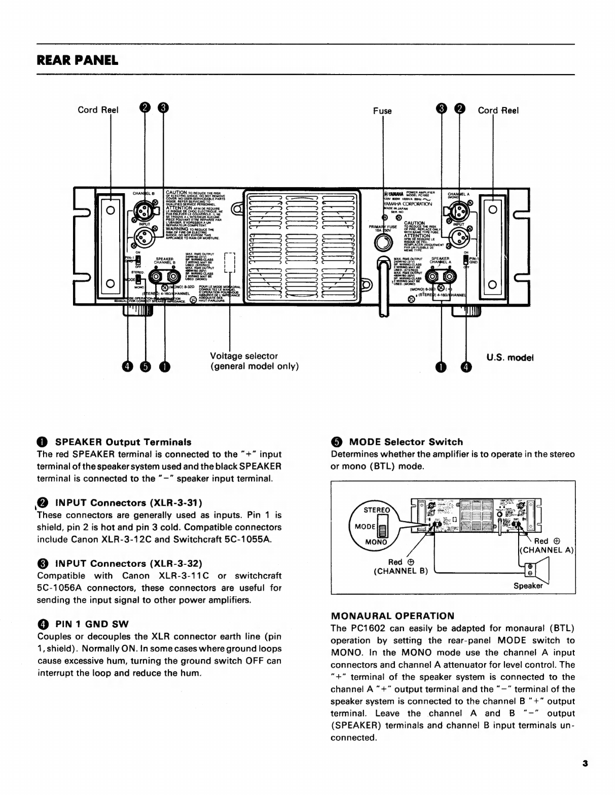
REAR
PANEL
CONTROLS
Mode
switch
........................................
STEREO/MONO
Pin
1
GND
switch
(XLR
connectors)
.............
ON/OFF
Voltage
selector
switch
(general
model
only)
PROTECTION
CIRCUITS
Muting
................
6
£2
seconds
after
power
turned
ON
DC
setise
aaa
a
зенан.
DC
+2
V
output
voltage
Thermal
protection
........
>
85°С
heat
sink
temperature
PC
limiter
..................................
RL
>
2
ohms when
ON
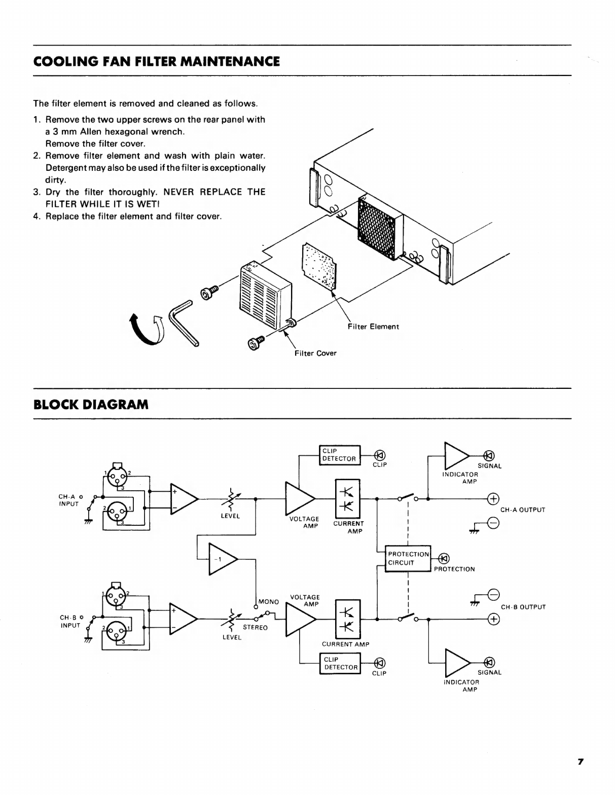
COOLING
FAN
CIRCUIT
Fan
ON
temp
................
reae
>
60°С
heat
sink
temp.
Fan
OFF
temp
................
<
45°C
heat
sink
temperature
POWER
REQUIREMENTS
U.S.
&
CANADIAN
models
................
AC
120
V,
60
Hz
GENERAL
model
...................
AC220/240
V,
50/60
Hz
POWER
CONSUMPTION
U.S.
&
CANADIAN
models
................
800
W,
1000
VA
GENERAL
model
.................................................
800
W
DIMENSIONS
(WxDxH)
ылыныы
ниди
480
x
431.3
x
140
mm
(18-7/8"
x
17"
x
5-1/2")
WEIGHT...
eei
21.7
kg
(47.8
Ibs)
NOTE:CANADIAN
models
must
be
operated
into
8
ohms
in
stereo
mode
and
16
ohms
in
mono
mode
in
ac-
cordance
with
safety
regulations.
IMPORTANT
NOTICE
FOR
THE
UNITED
KINGDOM
Connecting
the
Plug
and
Cord
IMPORTANT.
The
wires
in
this
mains
lead
are
coloured
in
accordence
with
the
following
code:
BLUE
:
NEUTRAL
BROWN
:
LIVE
Asthe
colours
of
the
wires
in
the
mains
lead
of
this
apparatus
may
not
correspond
with
the
coloured
markings
identifying
the
terminals
in
your
plug
proceed
as
follows:
The
wire
which
is
coloured
BLUE
must
be
connected
to
the
terminal
which
is
marked
with
the
letter
N
or
coloured
BLACK.
The
wire
which
is
coloured
BROWN
must
be
connected
to
the
terminal
which
is
marked
with
the
letter
L
or
coloured
RED.
All
specifications
subject
to
change
without
notice.