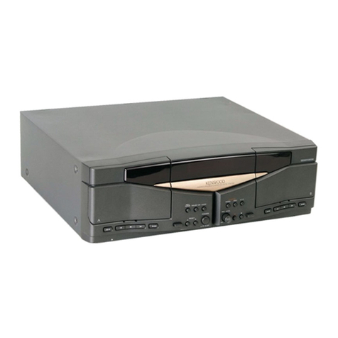
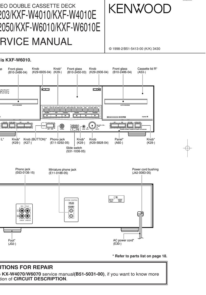
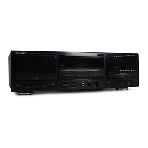
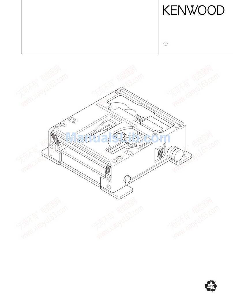
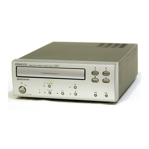
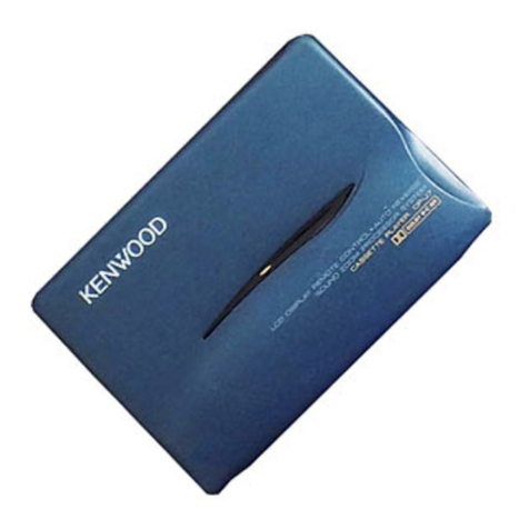
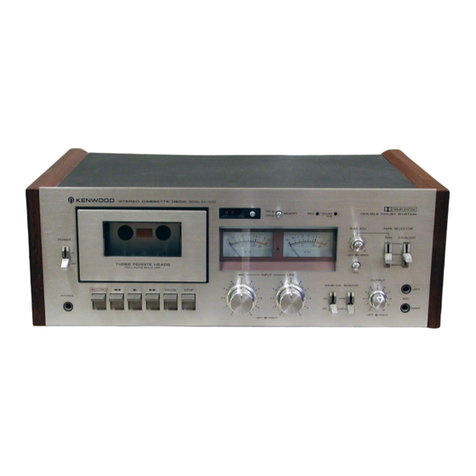
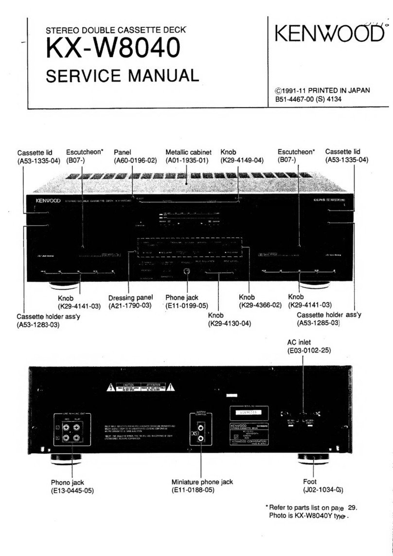
Kenwood X-E5 User manual

|
STEREO
DOUBLE
AUTO
REVERSE
CASSETTE
DECK
vac:
KENWOOD
SERVICE
MANUAL
|
|
|
|
(U
D-502)
|
©
1994-8
PRINTED
IN
KOREA
|
B51-4944-00(
K)
2461
Cassette
lid
(A)
Metallic
cabinet
Front
glass
(A)
Front
glass
(B)
Cassette
lid
(B)
(453-1806-02)
{A01-3144-11)
(B10-2032-02)
(B10-2033-02)
{A53-1807-02)
j
|
|
|
|
eee
|
|
i
|
|
i
|
|
|
|
Knob
(EJECT)
Panel
(FRONT)
Front
glass
(CD)
Panel
(CD
TRAY)
Knob
(OPEN/CLOSE)
Knob
(EJECT)
(K29-5983-04)
(A60-0596-11)
(B10-2034-13)
(A29-0371-03)
(K29-5947-04)
(K29-5984-04)
PRECAUTIONS
FOR
REPAIR
*
Since
the
power
for
this
device
is
supplied
by
the
receiver/multi-command
(A-E5),
the
latter
or
the
jig
(PS-93UA
or
PS-94UA)
is
required
for
repair
of
the
former.
*
Since
this
device
does
not
have
operation
keys,
we
recommend
to
use
A-E5.
If
this
device
is
set
to
the
test
mode,
the
jig
can
be
used
*
For
the
operation
of
the
cassette
mechanism,
see
Service
Manual
(B51-4869-00)
of
RXD-C3/C3L.

ES
CONTENTS
EXTERNAL
VIEW
........00..cccccccccceceeseseseseeesensereessees
2
WIRING
DIAGRAM
0000...
ceeeceneeseetneeetteseneee
ACCESSORIES
i:
8.
toscscesveee
dis
liettntiateens
3
PC
BOARD
(COMPONENT
SIDE
VIEW)
PS-93UA
or
PS-94UA
0...
eect
cerns
entees
4
SCHEMATIC
DIAGRAM
CONTROL
sie
cisatieces
odessa
satetacetvstueaes
ssindaattnate
daa
6
EXPLODED
VIEW
REMOTE
CONTROL
OPERATION
..........0cc:cceceee
7
(CD
MECHANISM)
BLOCK
DIAGRAM
.....0.0.....00.cc
i
ceeccecseeceeeeeeseeeeeeeeees
8
(CASSETTE
MECHANISM)
CIRCUIT
DESCRIPTION
0...
cece
cess
ee
eneer
ene
10
(UNIT)
cscdeecisteeesectnedt
bajvogecaidagsstnnecventertesbenvasenienes
ADJUSTMENT
.........00.
ee
19,
20, 22,
23,
25~31
PARTS
LIST...
ADIUSTES
-iciccsicssetcecsecetessinciaiteveaectveeavensneiias
21,
24
SPECIFICATIONS
...00....
ee
eee
eens
EXTERNAL
VIEW
:
REAR
PANEL
CONTENTS/EXTERNAL
VIEW
Cord
with
connector
(19PIN)
{E30-2771-05)
CLASS
1
|
LASER
PRODUCT
|
egsesnsc
|
KENWOOD
XES
STEREO
CASSETTE:CD
!
Foot
(J02-0370-05)

X-E5
ACCESSORIES
ACCESSORIES
System
configuration
*
FM
indoor
antenna
(T90-0182-15)
*
AC
plug
adaptor
(E03-0115-05)
(T90-0198-05)
Except
for
the
U.S.A.,
Canada,
Europe,
U.K.
and
Australia.
For
the
unit
with
a
European
AC
plug
in
areas
other
than
Europe.
*
Remote
control
unit
(RC-E5)
8
Batteries
(A70-0981-05)
Battery
cover
(A09-0106-08)
Beware
of
condensation
When
water
vapor
comes
into
contact
with
the
sur-
face
of
cold
material,
water
drops
are
produced.
If
condensation
occurs,
correct
operation
may
not
be
possible,
or
the
unit
may
not
function
correctly.
This
is
not
a
malfunction,
however,
and
the
unit
should
be
dried.
(To
do
this,
turn
the
POWER
switch
ON
and
leave
the
unit
as
it
is
for
several
hours.)
System
(Destination)
Receiver/Multicommand
|
Cassette
deck/CD
player
|
System
carton
box
(Parts
No.)
|
Speaker
(Other
package)
UD-502
(M,
X,
Y)
A-E5 X-E5
UD-502
{E,
T,
G)
A-EBL
Po
ES
LS-E5
«
AM
loop
antenna
ass'y
(T90-0195-05)
0
;
«
Antenna
adaptor
H60-0225-04
LS-E5
Loop
antenna
stand
(J19-3645-05)
*
Speaker
cords
(E31-5479-08)
*Speaker
cords
are
packed
with
the
Speakers.
Be
especially
careful
in
the
following
conditions
:
e¢
When
the
unit
is
brought
from
a
cold
place
to
a
warm
place,
and
there
is
a
large
temperature
difference.
e
When
a
heater
starts
operating.
e
When
the
unit
is
brought
from
an
air-conditioned
place
to
a
place
of
high
temperature
with
high
humid-
ity.
¢
When
there
is
a
large
difference
between
the
interna!
temperature
of
the
unit
and
the
ambient
tempera-
ture,
or
in
conditions
where
condensation
occurs
easily.

X-E5
PS-93UA
or
PS-94UA
Model
:
PS-93UA
or
PS-94UA
Power
supply
for
the
audio
model
UD
series.
Audio
signal
lines
in
15P
and
19P
flat
cable
are
con-
nected
to
RCA
connectors.
Explanation
of
the
function
@
POWER
SWITCH
This
switch
should
be
turned
on
when
using
the
15
pin
PRE
CD
DECK
@,
the
19
pin
PRE
CD
DECK
©
and
4
pin
power
supply
©.
@
15
PIN
POWER
AMP
Connect
to
a
system
which
require
the
15
pin
flat
cable
for
connection,
when
check
the
power
amp.
section.
AC
power
source
is
not
output
from
the
terminal.
The
signals
are
input
and
output
to
the
RCA
termi-
nals
and
SYNC
terminal
on
the
front
panel.
(ex
:
A-711,
A-722,
A-A7,
B-992,
B-AY,
etc)
®
15
PIN
PRE
CD
DECK
Connect
to
a
system
which
require
the
15
pin
flat
cable
for
connection,
when
check
the
functions
ex-
cept
power
section
AMP.
The
AC
power
are
supplied
to
the
pin
No.12,
13
for
QV
and
the
pin
No.14,
15
for
16V
from
the
terminal.
The
signal
flow
are
same
as
15
pin
power
AMP
ter-
minal.
(ex
:
DP-711,
DP-722,
DP-A7,
C-922,
X-711,
X-722,
X-A7,
etc)
®
19PIN
POWER
AMP
Connect
to
a
system
which
require
the
19
pin
flat
cable
for
connection,
when
check
the
power
AMP
section.
The
AC
power
is
not
supplied
in
the
terminal.
The
signals
are
input
and
output
to
the
RCA
terminal
on
the
front
of
panel.
(ex
:
A-B7,
A-B3,
B-B9,
A-E5,
A-E7,
B-E9,
etc)
KENWOOD
MODEL
PS-93UA
or
PS-S4UA
®
19
PIN
PRE
CD
DECK
Connect
to
a
system
which
require
the
19
pin
flat
cable
for
connection,
when
check
the
component
except
power
AMP.
This
terminal
have
the
4
sys-
tem
AC
power
supplies
which
is
located
to
the
pin
No.13
to
pin
No.19.
(ex
:
X-B9,
X-B5,
X-B3,
C-B9,
DP-B5,
DP-MB5,
X-E5,
X-ME5,
X-E7,
X-ME7,
DP-E9,
X-E9,
C-E9,
etc)
SYNC
TERMINAL
Connect
to
the
SYNCHRO
CHECK
JIG
KSJ-0816.
It
can
be
controlled
the
system
code
8
bit
or
16
bit
to
the
test
set.
4
PIN
POWER
SUPPLY
Output
terminal
for
AC
9V
and
ACI16V.
It
can
be
used
supply
the
AC
power
to
DECK,
CD,
TUNER
for
MIDI
system.
TAPE
SWITCH
The
signal
for
deck
of
19
pin
terminal
are
share
a
well
with
the
REC
and
PLAY.
So,
please
change
the
TAPE
SW
when
DECK
mode
is
PLAY
or
STOP
then
turn
to
the
play,
when
DECK
mode
is
REC
or
REC
pause
then
turn
to
the
REC.
(ex
:
X-B9,
X-B5,
X-B3,
X-E9)
Note
For
limited
power
supply's
capacity,
maximum
con-
nection
is
only
one
sets.
Do
not
connect
a
set
together
both
with
the
15
pin
terminal
and
19
pin
terminal.
In/output
signals
will
shift
as
specified
in
the
caution
label
when
A-E5,
A-E7,
X-E5,
X-ME5,
X-E7,
and
X-
ME7,
PLAY
+
TAPE
REC
CD
-—
TAPE
PLAY
LINE
+
CD
>,
Go.
GO
Cc
| |
Co
CO
©
Cc
OUT
REC
TAPE
Le
PLAY
TAPE
REC
15P
POWER
AMP
15P
PRE
CD
DECK
19P
POWER
AMP
19P
PRE
CD
DECK

feo)
Nn
E4
€O)
LINECL)
(OD)
LINR(R)
DOO
ODOOOOY
OO
O:0
O:0.0'0.6
$3
V-SEL-S¥
Pil
_}encizo
VNt6-Sd
19
YNEB-Sd
SA-X

X-E5
CONTROL
Cassette
deck
unit
KENWOOD
rento
souste
auro
nevense
caserre
orcx
x65
HX
PRO
Deira
AUTO
TAPE
SELECTOR
AUTO
TAPE
SELECTOR
AUTO
REVERSE
B
euvoack
meconoine
AUTO
REVERSE
O
Deck
A
eject
key
O
Deck
B
eject
key
@
Deck
A
cassette
holder
@
Tape
running
indicators
©
Deck
B
cassette
holder
EDIT
mode
indicators
RANDOM
indicator
REPEAT
indicator
Program
Check
indicator
PGM
indicator
SINGLE
TIME/TOTAL
TIME
indicators
SPACE
indicator
Track
number
CCRS
indicator
indicators
Play
indicator/Pause
indicator
Display
Time
display
Playing
TRACK
NO.
display
KENWOOD
comencr
onc
eaves
TEBITT
SoS
convenver
@
Disc
tray
@
Tray
open/close
key

X-E5
REMOTE
CONTROL
OPERATION
Remote
control
unit
Some
of
the
keys
of
this
remote
control
unit
have
variable
functions.
Before
pressing
one
of
these
keys,
please
to
make
sure
that
the
input
of
the
system
has
been
set
to
the
desired
source.
SLEEP
key
Press
to
activate
the
sleep
timer
func-
tion.
Graphic
equalizer
operation
keys
EG.EFFECT
-:Press
to
select
a
graphic
equalizer
ef-
—
fect.
PRESENCE
Press
to
select
a
pres-
ence
effect.
DEPTH
:Press
to
add
depth
to
the
sound
field.
POWER
key
Input
selector
(basic
operation)
keys
DISC SKIP
key
Press
to
select
the
disc
to
be
played
on
the
CD
player.
The
functions
are
variable
depend-
ing
on
the
input
mode
or
the
power
ON/OFF
status.
(This
key
is
invalid
with
the
UD-502.)
A/B
key
REC/ARM
key
'
Press
to
select
the
cassette
deck
be
oper-
Press
to
start
recording.
When
the
key
|
ated.
is
pressed
during
recording,
the
tape
stops
after
leaving
a
non-recorded
f
space
of
4
seconds.
:
0.T.E.
(One-Touch
Edit)
key
Press
to
record
the
CD
track
being
played
onto
tape,
etc.
Numeric
keys
bE
Function
as
the
numeric
keys
of
the
CD
‘
player
when
the
CD
input
is
selected.
DUAL
SOUND
key
Press
for
Environmental
Sound
play
(mixed
playback
of
CD
and
another
source).
K€,
PP,
Band
pi
keys
Use
these
keys
to
operate
the
CD
player
during
environmental
sound
play.
CD
player
operation
keys
E
TIME
‘Press
to
switch
the
time
display
mode.
CLEAR
:Press
to
clear
the
con-
tents
of
a
program.
KENWOOD
REMOTE
CONTROL
UNIT
VOLUME
CONTROL
keys
CHECK
-Press
to
display
the
pro-
AC-ES
Press
to
adjust
the
overall
volume.
grammed
contents
in
When
these
keys
are
pressed,
the
cur-
order.
:
rent
volume
level
is
displayed
on
the
SPACE
‘Press
to
leave
non-re-
§
receiver
unit.
corded
spaces
of
a
few
§
MUTE
key
seconds
between
the
:
Model:
RC-E5
Press
to
mute
the
sound
temporarily.
programmed
tracks.
:
Infrared
ray
system
EDIT
MODE
-Press
to
select
the
edit
§
recording
mode.
:
LONG
PLAY
-Press
for
long-hour
playback.
:
P.MODE
:Press
for
program
play-
back.
E
RANDOM
_:Press
to
start
random
§
playback.
REPEAT
:Press
to
start
repeated
playback.
Super
woofer
operation
keys
S.W.
VOLUME
:Press
to
adjust
the
volume
of
the
super
woofer
(optional).
S.W.
POWER
:Press
to
switch
the
power
of
the
super
woofer
(optional).

16.9344MH.
7
|
CLOCK
IC52
IC56
LOADING
DRIVER
TRAY
POSITION
(1bit)
SM5875BM
CLK
4.19MHz
rr
x<
CDM-22
RVO
y-COM
walla
PICK
KSS-240A
OL
uPD78044
CONT
CXA1372Q
AGF-018
FL
DISPLAY
OPN
n
—
1o)
1C55(2/4)
TRACKING
COIL
TRACKING
fe
DRIVER
Q502
1C55(3/4)
aeoer
a
at
SLED
MOTOR
SLED
—
DRIVER
P|
1C55(4/4)
F1,2
me
DISC
MOTOR
DISC
MOTOR
DRIVER
CN53
OOEOCQOOLHO
V|O
Reh
A-GND
Lech
AC
AC
to
DECK
SRQ1
and
SCK
SDT
Si
MRQI
INVYSVIG
19018
go
SA-X

BIAS
BIAS
LR
~
28.2dBs=30mV
SYSTEM
IC
IC11
4x6
RESISTOR
MATRIX
Q25,26,30
RM—>(X)
pe
AN,
OSC
ae
BIAS
-
ERASE
Q28 Q27
400/12.5K
AUTO
AUTO
BIAS
400/12
sk—>(X)
*—
BIAS
esd
PH
A,B
”
CPM
AB
{LEVEL
CONDITION)
ELE.VOL
(RESET)
:—15dB
1]
a
—1dBs=680mV
|
|
L
ee
2
T
OdBs=775mV
=
—
Q21,22
~«—_¢e—_|—_1—
¢9
+
9
‘©
es
|
TIMMS
>
+
@
Q
-Q
|
=
Q51~54
(2)
(3)
(4)
(5)
.
6)
g
@
-
(8)
(9)
(9
SYSTEM
IC
BIAS
P.B.
AMP
MECHA
1C1
Q1,2,1C10
CN2
A.GND
R\
Tape
_
|
PLAY
L
\
TAPE
a}
REC
sRQ1
sRa2
to
MCK
=>
RECEIVER
MDT
A-E5
SOT
MRQ1
H\cp
c¢
|
ACOV
H
\
Tape
AC16V
CN1
INVYSVIG
19078
4940
SA-X

X-E5
CIRCUIT
DESCRIPTION
1.
CD
p-com
:
1
PD78044AGF-018
(X28-2662-70
:
IC53)
1-1.
Pin
connection
@
PULL
UP
4
PULL
DOWN
(100k)
oe
=
oQ24e
DM
®
vo
ew
fnwe
£
E
SEE
ER
Pa
NOR
©
OPEN/etc.
Pe
ae
eee
ee
7G
1
fe)
6G
2
p
5G
3
|
4G
4
k
3G
5
Q
2G
6
D
1G
7
a)
Vpp
8
a
SQCK
9
J
g
10
oO
SUBQ
11
Q
SLT
SW
Q
aa
uPD78044AGF-018
ne
MCK
O
OPEN
SW
SDT
O
CLOSE
SW
MDT
O
o
RESET
SENSE
GFS
a)
O
MRQ1
OPEN
M
SCOR
CLOSE
M
Qa
Q
a
Ql
LDC
gogdgdao
+ *
CO]
oO
x“
Qa
“¥“qeuiro9
a
2
XK
=
¥
2
>
OG
E5
ads
a}
10

CIRCUIT
DESCRIPTION
1-2.
Pin
function
Grid
7~1
for
FL
display.
Pa
Power
supply.
(+5V)
(So
eee
CXD25070
Output
of
clock
to
read
Q
data
o
used.
PULL
DOWN
XD25070
Input
OQ
data.
Nput
start
limit
switch.
‘or
system
communication.
Output
clock.
i
=
z
7
10
11
12
Q
Cc
nln|
on
o\<Iy
=
O[LIO
O
oo
co)
ea
O
nx
=
=
LT
SW
13
For
system
communication.
Output
request.
14
MCK
15
SDT
or
system
communication.
Output
data.
16
MDT
or
system
communication.
Input
data.
17
ESET
18
SENSE
19
eset
XD25070
Input
sense.
XD25070
GFS
detect
input.
used.
|
fo)
N
Oo
oO
21
22
23~2
28
29,
3
3
PEN
M
LOSE
M
pen
motor
control.
lose
motor
control.
0
used.
lo
used.
FOK
detect
input.
Ie
el
lo
used.
CXD25070Q
Input
system
clock.
a
No
used.
OPEN
Q
Tas
z|z\|m
z
Q]Z|m/Zz|/z}2
Zz
9
oO
WI]
WI]
BILWIN
Kn oO
n
Ww
ao
~
=
©
Ww
~“
36
CLK
CXD2507Q
Output
clock.
es
=
tee
eee
37
CXD25070
Output
data.
fs
38
CXD2507Q
Output
latch.
ago
poe
ek
ee
el
39
Digital
mute
control.
ae
aan
No
used.
a1
Oviput
laser
signal
Men
ae
Ce
al
0
used.
44
Sub
code
frame
sync
detect
input.
oe
|
45
or
system
communication.
Input
request.
A
nea
eked
a
0
used.
4ga9
[-
No
used.
50
[Input
close
switch,
51
input
open
switch.
SSCS
SSS
57
Two
Power
suppy.(@5)
SS
SSCOSCSCSCSC~iYSC
es-60
[~
Tt
Noused
PULL
DOWN
61~68
Segment
k,
|,
p,
0,
m,n,
i,
|
for
FL
display.
(SCAN7~0)
J
ttaese
ss
eT
nd
Segmenth
dforFldsply.
SCSC~C“‘C~‘idYSC“‘C‘C;*;*~*'
cS
1
3
[SegmentciegfbaforFidisplay
Grid
10~8
for
FL
display.
fy
te
8
=
11

X-E5
CIRCUIT
DESCRIPTION
2.
DECK
p.-com
:
CXP84340-1110
(X28-2662-70
:
IC3)
2-1.
Pin
connection
wu
m
PULL
UP
2
=
2
aa
eh
PULL
DOWN
5
Q@eu
au
>
-
ay
oma
5
ke ik
a
Ww
DD
ezqea
22233683278
qoa
*
goood
O
Vss
©
OPEN/etc.
on
ao
™~
ERASE
1
Q
BLED
L 2
7
BLED
R
3
Q
UD752
ALEDL
4
MRQ2
ALED
R
5
Oo
CE
SOLA
Q
6
™
OSC
OUT
CPMA
Q
7
5
CSPAQ
8
CRO2A
SOLB
9
HALF
A
CPMBQ
PLAY
A
CSPB
JONSP
X
4
m
SYSDT
JOHSP
©
CXP84340-1110
a
SYSsT
™
SYSCK
Q
Q
SDT
MDT
MCK
PHA
Li
SROQ2
PHB
REC
MUTE
©
g
LINE
MUTE
Q
©
400/12.5kHz
KRO
Q
READ
KR1
Q
Q
BIAS
KR2
0
™@
E2PROM
CLK
GU
UO
OU
YY
8FeGgeege¢g
og
@
CG
Mor
NOME
3B
4
Aauonke
CHRHAAKRHZASRHEZHTTSH
¥vMYYY
EEE
-F
2s
ua
x
xX
2>a>s2
uu
<
wii
O
o
4
oO.
N
uu
12

2-2.
Pin
function
Pin
name
X-E5
CIRCUIT
DESCRIPTION
Function
ERASE
(PF3)
©
Port
for
turning
on/off
ERASE
head.
¢
Turned
on
only
in
REC
operation.
H:
ON,
L
:
OFF
(PF4)
7
CPMA
(PD1)
CSPA
(PD2)
1
nN
14-17
(PC4
|
14-17
_|
PHA
PHB
=
©
SOLA
(PDO)
ree
O
SOLB
(
PD3)
O
(PD4)
O
13
7OHSP
(PD7)
O
|
(PCO~PC3)
)
nN
oO
REC
MUTE
LINE
MUTE
(PC6)
(PC7)
i)
¢
Port
for
LED
on
left
side
of
Amechanism
reel
shaft.
©
Lights
up
when
power
is
turned
on.
Flashes
while
mechanism
is
in
operation,
however.
H
:
Lighting
up,
L
:
Going
off
©
Port
for
LED
on
right
side
of
A-mechanism
reel
shaft.
¢
Lights
up
when
power
is
turned
on.
Flashes
while
mechanism
is
in
operation,
however.
H
:
Lighting
up,
L
:
Going
off
¢
Port
for
LED
on
left
side
of
B-mechanism
reel
shaft.
¢
Lights
up
when
power
is
turned
on.
Flashes
while
mechanism
is
in
operation,
however.
H
:
Lighting
up,
L
:
Going
off
¢
Port
for
LED
on
right
side
of
B-mechanism
reel
shaft.
¢
Lights
up
when
power
is
turned
on.
Flashes
while
mechanism
is
in
operation,
however.
H
:
Lighting
up,
L
:
Going
off
Port
for
turning
on/off
A-mechanism
solenoid.
¢
Condition
of
mechanism
is
changed
by
changing
length
of
time
while
this
port
is
set
to
H
level.
Turned
on
only
during
transition.
H
:
ON,
L:
OFF
©
Port
for
turning
on/off
A-mechanism
capstan
motor.
¢
Mechanism
is
in
operation,
this
port
is
kept
at
H
level.
Capstan
motor
is
turned
off
only
when
mechanism
is
stopped.
H
:
ON,
L:
OFF
©
Port
for
speed
control
of
Aemechanism
capstan
motor.
¢
While
this
port
is
at
L
level,
capstan
motor
turns
at
double
normal
speed.
Set
to
L
level
only
while
high-speed
dubbing
and
transition
of
mechanism.
H:
Normal,
L
:
Double
speed
Port
for
turning
on/off
B-mechanism
solenoid.
¢
Condition
of
mechanism
is
changed
by
changing
length
of
time
while
this
port
is
set
to
H
level.
Turned
on
only
during
transition.
H
:
ON,
L
:
OFF
¢
Port
for
turning
on/off
B-mechanism
capstan
motor.
*
Mechanism
is
in
operation,
this
port
is
kept
at
H
level.
Capstan
motor
is
turned
off
only
when
mechanism
is
stopped.
H
:
ON,
L:
OFF
¢
Port
for
speed
control
of
B-mechanism
capstan
motor.
¢
While
this
port
is
at
L
level,
capstan
motor
turns
at
double
normal
speed.
Set
to
H
level
only
while
except
high-speed
dubbing
and
transition
of
mechanism.
H:
Normal,
L
:
Double
speed
¢
Port
for
changing
normal
playback
equalizer.
©
Turned
on
while
chromium
tape
is
played
nor-
mally.
Default
is
OFF
and
bias
of
120us
is
applied.
H
:
ON
(70ps),
L
:
OFF
(120s)
*
Port
for
changing
double-speed
playback
equalizer.
¢
Turned
on
while
chromium
tape
is
played
at
double-speed.
Default
is
OFF
and
bias
of
120s
is
applied.
H:
ON
(70s),
L
:
OFF
(120ps)
e
Unused
terminals.
*
Photo-sensor
input
port
of
A-mechanism.
®
Light
is
applied
to
reflector
at
rear
of
reel
stand.
H/L
is
judged
by
reflected
light
to
sense
running
of
tape
and
use
result
for
counter.
e
Running
of
tape
is
sensed
at
both
edges.
Counter
counts
one
every
four
senses.
¢
Photo-sensor
input
port
of
B-mechanism.
®
Light
is
applied
to
reflector
at
rear
of
reel
stand.
H/L
is
judged
by
reflected
light
to
sense
running
of
tape
and
use
result
for
counter.
e
Running
of
tape
is
sensed
at
both
edges.
Counter
counts
one
every
four
senses.
¢
Mute
just
before
REC
EQ.
¢
Turned
off
only
during
REC
operation.
H
:
OFF,
L:
ON
e
Mute
at
LINE
OUT
of
playback
system.
¢
Turned
off
only
during
playback
and
recording
opera-
tion,
including
transition
time
of
mechanism.
H:
OFF,
L:
ON
KRO~KR3
KSO-~KS3
-|o
EXTAL
(EXTAL)
XTAL
(XTAL)
34
Ww
(oa)
TEX
(TEX)
AVand
(AVGND)
O
|
©
Key
return
port
for
test
mode.
©
Key
is
taken
through
this
port
to
realize
test
mode
with
key
of
body.
®
Key
scan
port
for
test
mode.
¢
Key
is
taken
through
this
port
to
realize
test
mode
with
key
of
body.
*
TSCN3
composes
short
matrix
of
test
mode.
Reset
terminal
of
device.
¢
Terminal
for
oscillation
of
device.
*
10
MHz
is
connected.
©
Terminal
for
oscillation
of
device.
¢
10
MHz
is
connected.
©
Grounding
terminal.
©
Terminal
for
sub-oscillation
of
device.
¢
Unused.
¢
Terminal
for
sub-oscillation
of
device.
¢
Unused
¢
Terminal
for
ground
level
of
A/D
conversion.
®
Generally,
potential
of
Vss
is
input.
AVREF
(AVREF)
LEVEL
L
(PAO)
LEVEL
R
(PA1)
E’-PROM
DT
(PA2)
ie)
W)1@
wo
i
|
0
¢
Terminal
for
upper
level
of
A/D
conversion.
*
Generally,
potential
of
VoD
is
input.
Port
for
detection
of
L-channel
signal
level
of
tape.
*
A/D
conversion
is
performed
to
detect
level.
©
Port
for
detection
of
R-channel
signal
level
of
tape.¢
A/D
conversion
is
performed
to
detect
level.
@
Port
for
reading
and
writing
data
of
E-7PROM.
e
All
data
which
deck
must
save
are
written
in
this
IC.
13

X-E5
CIRCUIT
DESCRIPTION
©
Port
for
supplying
clock
for
E7PROM.
e
Port
for
turning
on/off
bias
for
REC
operation.
*
Turn
on
only
during
REC
operation.
H:
ON,
L:
OFF
©
Port
for
turning
on/off
addition
capacitive
load
for
removing
ripples
from
signal
when
level
is
read
in
automatic
adjustment
or
ATCS
operation.
*
Normally
turned
off.
H:
ON,
L
:
OFF
e
Port
for
changing
filter
for
automatic
adjustment.
¢
Filter
is
changed
according
to
OSC
output.
H:
12.5
kHz,
L
:
400
kHz
41
E?PROMCLK
(PA)
42
BIAS
(PA4)
43
READ
(PA5
44
400/12.5kHz
(PA6)
=
P=
’=
(<o)
co
for)
45,
4
f=
(PAZ,
PBO)
|
e
Unused
terminal.
47
SRQ2
(PB1)
¢
Stand-by
port
for
communication
with
receiver
and
request
for
and
receiving
data
from
deck.
¢
Micro-controlier
of
deck
set
this
port
to
H
level
to
request
for
release
of
bus
from
master
(micro-
controller
of
receiver)
when
sending
data.
*
When
receiving,
micro-controller
of
deck
notifies
receiver
that
it
is
ready
to
receive
data.
H
:
Request,
Ready,
L
:
In
communication,
bus
released
MCK
(PB2)
©
Terminal
for
communication
with
receiver
and
input
of
outside
clock.
®
Deck
sends
and
receives
data
according
to
clock
output
by
receiver.
*
Used
as
SERIAL
COMMUNICATION
BUSY
terminal
when
started
in
unit
mode.
MDT
(PB3)
¢
Terminal
for
communication
with
receiver
and
input
of
master
data.
¢
Data
for
deck
are
input
ie
through
this
terminal.
e
Used
as
SERIAL
COMMUNICATION
DATA
terminal
when
started
in
unit
mode.
SDT
(PB4)
fer
Terminal
for
communication
with
receiver
and
output
of
slave
data.
«
Data
from
deck
are
output
through
this
terminal,
synchronized
with
MCK
clock.
51
e
Clock
port
for
control
of
system
IC.
52
SYSST
(PB6)
53
SYSDT
(PB?)
(PEO)
PLAY
A
(PE1)
®
Strobe
port
for
control
of
system
IC.
©
Data
port
for
control
of
system
IC.
¢
Unused
terminal.
¢
SW
to
detect
A-mechanism
head
position.
¢
This
port
is
tested
at
every
point
of
transition
of
mechanism.
For
example,
if
head
is
lifted
up
at
last
of
playback,
this
port
is
set
to
L
level.
H
:
Head
DOWN,
L
:
Head
UP
©
SW
to
detect
tape
in
A-mechanism.
©
Tape
in
mechanism
is
judged
by
condition
of
this
port.
H
:
Tape
is
not
mounted,
L
:
Tape
is
mounted
*
SW
to
detect
chromium
tape
position
of
A-mechanism.
*
Chromium
tape
position
is
recognized
at
H
level.
H
:
Chromium
tape
position,
L
:
Normal
position
(PE4)
|
O
|
©
Unused
terminal.
OSC
OUT
(PE5)
¢
Output
terminal
of
oscillator
for
automatic
adjustment.
*
400
Hz
and
12.5
kHz
are
output.
(P10)
*
Terminal
to
detect
chip
enable.
¢
Port
to
detect
turning
off
of
power.
H
:
Power
is
turned
on,
L
:
Power
is
turned
off.
¢
Stand-by
port
for
communication
with
receiver
and
request
for
and
receiving
data
from
master.
¢
Micro-controller
of
deck
confirms
that
this
port
is
set
to
H
level
before
starting
transmission,
and
recognizes
transmission
from
master
when
this
port
is
set
to
H
under
normal
condition.
This
detection
is
made
at
interruption
level.
H
:
Request,
Ready,
in
communication,
L
:
Bus
released
*
Pulled
up
when
used
in
mode
of
UD-752.
H
:
UD-752
mode,
L
:
UD-502/562
mode
©
Unused
terminal.
¢
SW
to
detect
metal
tape
position
of
B-mechanism.
©
Detects
only
in
UD-752
mode.
¢
Recognize
metal
tape
position
at
H
level.
H
:
Metal
tape
position,
L
:
Normal
or
chromium
tape
position
©
SW
to
detect
B-mechanism
head
position.
*
This
port
is
tested
at
every
point
of
transition
of
mechanism.
For
example,
if
head
is
lifted
up
at
last
of
playback,
this
port
is
set
to
L
level.
H
:
Head
DOWN,
L
:
Head
UP
*
SW
to
detect
tape
in
B-mechanism.
©
Tape
in
mechanism
is
judged
by
condition
of
this
port.
H:
Tape
is
not
mounted,
L
:
Tape
is
mounted
*
SW
to
detect
chromium
tape
position
of
B-mechanism.
¢
Chromium
tape
position
or
metal
tape
position
is
recognized
at
H
level.
H
:
Chromium
tape
or
metal
tape
position,
L
:
Normal
position
©
Power
supply
terminal
for
device.
Empty
terminal.
Connected
to
Vdd.
©
SW
to
inhibit
recording
on
A-side
of
B-mechanism.
®
Set
to
L
level
when
recording
on
A-side
of
B-mechanism
is
inhibited.
H
:
Recording
is
permitted,
L
:
Recording
is
inhibited
B
HALF
A
(PE2)
57
CRO2A
(PE3)
59
61
MRQ2
(Pl1)
D752
(PI2
(PI3~PI7)
METAL
B
(PGO)
Cc
62
Lo]
2
fo}
~~
PLAY
B
(PG1)
70
HALF
B
(PG2
71
CRO2
B
(PG3)
nN
z\s
O16
sic
za
forked
74
INF
F
(PG4)
Ww
14

X-E5
CIRCUIT
DESCRIPTION
Pin
name
Function
INF
R
¢
SW
to
inhibit
recording
on
B-side
of
B-mechanism.
¢®
Set
to
L
level
when
recording
on
B-side
of
B-mechanism
is
inhibited.
H
:
Recording
is
permitted,
L
:
Recording
is
inhibited
Nor/ABIAS
(PG6)
¢
Port
to
change
level
in
automatic
adjustment.
¢
Level
is
changed
for
playback
mode
adjustment
and
recording/playback
mode
adjustment.
H
:
Recording/Playback
adjustment,
L
:
Playback
adjustment
(PG7)
e
Unused
terminal.
INPUT
MUTE
(PFO)
¢
Mute
at
inlet
of
REC
system.
©
Turned
off
when
REC
operation
starts.
Kept
turned
on
in
other
conditions.
H:
OFF,
L:
ON
(PF1)
¢
Port
to
select
A-mechanism
or
B-mechanism.
©
Since
two
mechanisms
are
installed
while
only
one
circuit
is
installed,
one
is
selected
with
this
port.
H
:
B-mechanism,
L
:
A-mechanism
(PF2)
¢
Port
to
select
head
route.
*
Used
to
select
playback
head
or
recording
head.
H:
Recording,
L
:
Playback
2-3.
Pin
explanation
¢
Features
(a)
Reverse-type,
double
deck
(A-
and
B-decks).
(b)
B-deck
can
record.
(c)
CCRS
and
CRLS
functions.
(d)
DPSS
skip
search
function
(16
stations
maximum).
(e)
Dolby
B,
C
(f)
Dubbing
function
(Normal
speed,
high
speed)
(g)
3-mode
direction
(One-way,
U,
endless)
(h)
Matched
to
long
play
and
one-touch
editing
func-
tions
(i)
Two
tape
positions
(Normal,
chromium)
¢
Controlled
items
(1)
Cassette
mechanism
Playback
mechanism
(D40-1363-*5)
Recording
mechanism
(D40-1364-*5)
(2)
System
IC
:
HA12167F
(3)
E7PROM
:
X24C01AP
15

X-E5
16
CIRCUIT
DESCRIPTION
3.
Test
mode
(Cassette
deck)
3-1.
Initial
setting
The
deck
is
set
initially
under
the
following
condi-
tions.
Power
Mechanical
mode
Direction
Right
to
operate
CCRS/CRLS
Operation
mode
DOLBY
NR
Input
REC
level
All
mute
Erasing
head
R/P
A/B
Reel
LED
>
ON
:
Stop
:
Both
A
and
B
are
set
forward.
:B
:
OFF
:
U
mode
:
OFF
:
Tuner
:
Initial
value
Playback
equalizer
:
>
ON
:
OFF
:
Play
[A
>
ON
120NSP
3-2.
Types
of
test
mode
(1)
Test
1
(2)
Manual
adjustment
(3)
Automatic
adjustment
3-3.
Setting
of
test
mode
The
machine
is
set
in
the
test
mode
under
the
follow-
ing
port
conditions
when
it
is
reset.
AUTO
ADJ
MANU
ADJ
TEST1
INITIAL
SET
DON'T
CARE
When
turning
on
the
power
for
the
Cassette
deck
in-
dependently,
be
sure
to
connect
AC16V
(No.
7
or
8)
and
D17
(ANODE)
of
(X28){A/6)
.
(Remove
this
connec-
tion
after
the
power
is
turned
on.)

X-E5
CIRCUIT
DESCRIPTION
3-4.
TEST
1
»
Setting
-
System
(A-E5+X-E5)
:
Shorting
the
No.
4
pin
to
the
No.
3
pin
by
a
diode
(Di-
rection:
No.4
—PF
No.
3),
press
the
[POWER]
key
of
the
receiver
(A-E5).
-
Unit
(X-E6)
:
Shorting
the
No.
4
pin
to
the
No.
3
pin
by
a
diode
(Di-
rection:
No.
4
—PE
No.
3),
turn
on
the
[POWER]
switch
of
the
power
supply
jig.
*
Resetting
.
System
(A-E5+X-E5)
:
Press
the
[CCRS/CRLS]
key
or
POWER
key
to
turn
off
the
power.
»
Unit
(X-E5)
:
Turn
off
the
POWER
switch
of
the
power
supply
jig
or
short
No.
1
of
CN9
to
No.
7.
*
Contents
and
operation
[
[Contents
System
|
*
Unit
13-sec
REC
[SKIP
UP]
key
(DBL)
normal
speed
playback
double
speed
playback
5
|
ABRVS
{SKIP
DOWN]
key(
K€)
|
3,
6
pin
normal
speed
playback
'6
|
CCRS
level
test
[NOR
DUBB}
key
3,7
pin
Electronic
volume
3-level
control
*Short
pins
of
CN9
for
the
independent
operation
of
unit.
¢
Allotment
of
keys
|
|
KS0
<5
pin>
|
KS1<6
pin>
|
KS2<7
pin>
RVS
normal
KRO
<3
pin>
STOP
(
Kd
)
(N/DUBB)
FWD
Double
KR1
<2
pin>
TAPE
peed
playback
DOLBY
(
>)
FWD
normal
Reset
KR2
<1
pin>
A/B
peed
playback}
Normal
(«)
(CCRS/CRLS)
Electronic
(REC)
(
ppl)
(H/DUBB)
<
>:CN9
(X28:
A/6),(
):
Keys
of
receiver
used
in
normal
mode
When
performing
this
operation,
press
the
keys
of
the
receiver
having
the
names
of
the
above
keys
used
in
the
normal
mode.
For
example,
since
the
[NOR
DUBB]
key
is
used
as
the
key
for
the
CCRS
test
in
the
normal
mode,
the
[NOR
DUBB]
key
of
the
receiver
is
used
for
this
pur-
pose.
¢
Indication
-
Items
indicated
with
LED
These
items
are
indicated
with
LED
in
either
the
sys-
tem
or
the
unit
mode.
The
LED
on
the
L
side
of
the
A-deck
indicates
the
tape type
of
the
half
in
the
A-deck,
and
the
R
side
indicates
the
tape
type
of
the
half
in
the
B-deck
as
follows.
Turned
off
:
Norma!
tape
Turned
on
:
Chromium
tape
The
LED
of
the
B-deck
indicates
the
condition
of
the
dolby.
B
REEL
LED
DOLBY
OFF
;
DOLBY
B
DOLBY
C
(Remarks)
O
:
Turned
off.,
@
:
Turned
on.
17

X-E5
18
CIRCUIT
DESCRIPTION
Specifications
The
machine
is
set
in
the
test
mode,
regardless
of
the
positions
of
the
switches
and
mounting
of
tapes.
Even
if
the
head
is
lifted
up,
the
following
operation
is
executed
after
initial
setting.
+
Initial
setting
The
REC
level
is
set
to
the
initial
level
(-15dB)
by
the
center.
¢
4-sec
REC
If
the
[REC]
key
is
pressed,
the
deck
records
for
4
seconds,
then
automatically
rewinds
to
the
starting
point
of
recording
and
plays
back.
The
REC
key
is
accepted
infinitely.
If
the
[REC]
key
is
pressed
again
during
4-sec
REC
operation,
the
machine
records
for
4
seconds
again
from
the
current
point,
then
rewinds
to
the
starting
point
of
the
first
4-sec
REC
and
plays
back.
If
a
tape
is
selected,
the
following
operation
starts.
@When
normal
tape
is
used
-
The
machine
performs
the
4-sec
REC
with
the
dolby
turned
off,
then
rewinds
to
the
starting
point
of
re-
cording
and
plays
back.
-
The
machine
plays
back
with
the
dolby
turned
off.
@When
chromium
tape
is
used
-
The
machine
performs
the
4-sec
REC
with
the
dolby
C
turned
on,
then
rewinds
to
the
starting
point
of
re-
cording
and
plays
back.
-
The
machine
plays
back
with
the
dolby
turned
off.
@When
metal
tape
is
used
-
The
machine
performs
the
4-sec
REC
with
the
dolby
B
turned
on,
then
rewinds
to
the
starting
point
of
re-
cording
and
plays
back.
The
machine
plays
back
with
the
dolby
turned
off.
After
playing
for
4
seconds,
the
machine
continues
playing
under
the
current
dolby
condition.
If
the
[STOP]
key
is
pressed,
the
operation
is
stopped
and
the
dolby
is
turned
off.
e
e
°
13-sec
REC
If
the
[SKIP
UP]
key
is
pressed,
the
deck
records
for
13
seconds,
then
automatically
rewinds
to
the
start-
ing
point
of
recording
and
plays
back.
The
[SKIP
UP]
key
is
accepted
infinitely.
If
the
[REC]
key
is
pressed
again
during
13-sec
REC
operation,
the
machine
records
for
13
seconds
again
from
the
current
point,
then
rewinds
to
the
starting
point
of
the
first
13-sec
REC
and
plays
back.
The
details
of
the
operation
are
the
same
as
the
4-sec
REC.
PLAY
for
adjustment
of
tape
speed
(Common
to
A-
and
B-mechanism)
If
the
[FF]
key
is
pressed,
the
machine
performs
high-
speed
FWD
playback.
If
the
[REW]
key
is
pressed,
the
machine
performs
normal-speed
FWD
playback.
If
the
two
keys
are
pressed
alternately
while
the
ma-
chine
is
playing,
the
head
is
not
lowered,
but
only
the
speed
is
changed.
If
the
[SKIP
DOWN]
key
is
pressed,
the
machine
per-
forms
normal-speed
RVS
playback.
Cyclic
change
of
electronic
volume
lf
the
[Hl
DUBB]
key
is
pressed,
the
volume
is
changed
(-.2
>
-15
dB
>
0
dB)
NOR-CCRS
(Confirmation
of
lowering
of
REC
vol-
ume
level)
If
the
[NOR
DUBB]
key
is
pressed,
recording
is
paused.
If
an
excessive
input
is
received,
the
record-
ing
level
is
lowered.

X-E5
ADJUSTMENT
Preparation
for
adjustment
1.
Supply
the
power
of
AC14~16V
from
the
main
amplifier
or
the
jig.
2,
When
performing
automatic
adjustment,
prepare
a
dolby
level
tape
(TCC-130
or
MTT-150)
and
a
tape
conformed
to
SCC-2280.
DOLBY
LEVEL
TCC-130
DOLBY
B-TYPE
TONE
DOLBY
B-TYPE
TONE
CALIBRATION
MTT-150
200nWb/m
:
af
DOLBY
LEVEL
SCC-2280
DOLBY
B-TYPE
TONE
—>—}+—
8sec
A
200nWb/m
50sec
Y
Alignment
Y
3.
If
a
synchronism
check
jig
is
available,
connect
it.
(KSJ-0816)
Connection
diagram
DECK
F
COUNTER
BZ,
A
ee
rae
ors
Q °
4
60
00
KSJ-0816
m4
OSCILLOSCOPE
{Is
3
8007
L___]CN2
OSCILLOSCOPE
Main
amp
+
Pre
amp
or
PS-93UA
or
PS-94UA
FRONT
FRONT
19

X-E5
ADJUSTMENT
Adjustment
(CD
player)
Test
mode
Display
Setting
of
test
mode
:
CN57
(X28
:
C/6)
Set
above
mode.
jefe
[30]
kw
ree
FOCUS
SERVO
ON
1,3
|
CHECK
|
TRACKING
SERVO
OFF
FEED
SERVO
OFF
EX.
Setting
of
test
mode
:
Shorting
the
No.
1
pin
to
the
No.
2
pin
Setting
of
alHight-up
mode
:
Shorting
the
No.
1
pin
to
the
No.
5
pin
FOCUS
SERVO
ON
TRACKING
SERVO
OFF
On
the
power
from
0.08
to
Apply
the
sensor
|
Short
1
pin
and
2
pin
of
CN57
0.15mW,
when
the
diffraction
section
of
the
and
enter
the
test
mode.
grating
is
correctly
a
ligned
LASER
POWER
optical
power
Short
1
pin
and
3
pin
of
CN57.
with
the
RF
level
of
1.5Vp-p
or
meter
on
the
The
LD
emets
light.
Then,
more
and
the
TE
(servo
open)
pickup
lens.
confirm
that
the
display
is
"03"
level
of
1.5Vp-p
or
more,
the
pickup
is
acceptable.
TRACKING
SERVO
ON
Cyclic
indication
of
all-light-up
mode/all-go-off
mode
of
LF
display.
FEED
SERVO
OFF
Test
disc
type
4
|
Connect
a
LPF
to
FEED
SERVO
ON
FOCUS
SERVO
OFF
STOP
INPUT
OUTPUT
ALIGNMENT
SETTING
SETTING
POINTS
Apply
signal
of
|
CN56
pin
2,3
to
FOCUS
GAIN
1.0kHz,
0.1Vrms
to
|
which
connect
an}
Short
1
pin
and
4
pin
of
CN57.
FOCUS
GAIN
Two
VTVMs
should
read
CN56
Pin
2,
3
oscilloscope
or
|
Confirm
that
the
display
is
"05".
VR51
the
same
value.
(X28
:
C/6)
10
AC
voltmeters.
(X28
:
C/6)
(X28
:
C/6)
(X28
:
C/6)
Connect
a
LPF
to
CN56
pin
5,
6
to
Test
disc
type
4
Apply
signal
of
TRACKING
GAIN
1.0kHz,
0.1Vrms
to
|
which
connect
an
|
Short
1
pin
and
4
pin
of
CN57.
TRACKING
GAIN
Two
VTVMs
should
read
CN56
Pin
5,
6
oscilloscope
or
|
Confirm
that
the
display
is
"05".
VR52
the
same
value.
{X28
:
C/6)
a
AC
voltmeters.
(X28
:
C/6)
(X28
:
C/6)
(X28
:
C/6)
(NOTE)
Type
4
disc
:
SONY
YEDS-18
TEST
DISC
or
equivalent.
LPF
:
Around
47k82+390pF
or
so.
(a)
Laser
power
(b)
Focus
gain,
(c)
Tracking
gain
w
Nh
=
ol
Focus
gain:
08~0.15mW
oe
<0
1.0kHz
0.1Vrms
Tracking
gain:
20
Other Kenwood Cassette Player manuals

Kenwood
Kenwood KX-W8050 User manual

Kenwood
Kenwood X-W320 User manual

Kenwood
Kenwood X-SE7 User manual

Kenwood
Kenwood KX-1030 User manual

Kenwood
Kenwood CT-403 User manual

Kenwood
Kenwood X-SG7G User manual

Kenwood
Kenwood CT-401 User manual

Kenwood
Kenwood KRC-19A/G User manual

Kenwood
Kenwood KRC-V791 User manual

Kenwood
Kenwood CT/KXF-W User manual

Kenwood
Kenwood CP-J7 User manual

Kenwood
Kenwood KDT-99R User manual

Kenwood
Kenwood X-W320 User manual

Kenwood
Kenwood R-SE7 User manual

Kenwood
Kenwood kx-3010 User manual
Kenwood
Kenwood KX-W8060 User manual

Kenwood
Kenwood KX-1030 User manual

Kenwood
Kenwood CT-401 User manual

Kenwood
Kenwood KRC-940 User manual
Kenwood
Kenwood X-SE7 User manual