CONTENTS
SAFETY INFORMATION ........................1
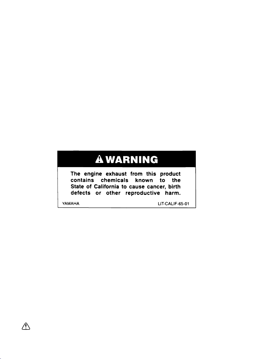
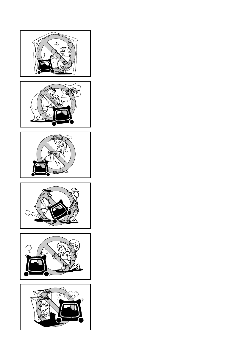
Exhaust fumes are poisonous ..............2
Fuel is highly flammable and
poisonous .............................................2
Engine and muffler may be hot.............2
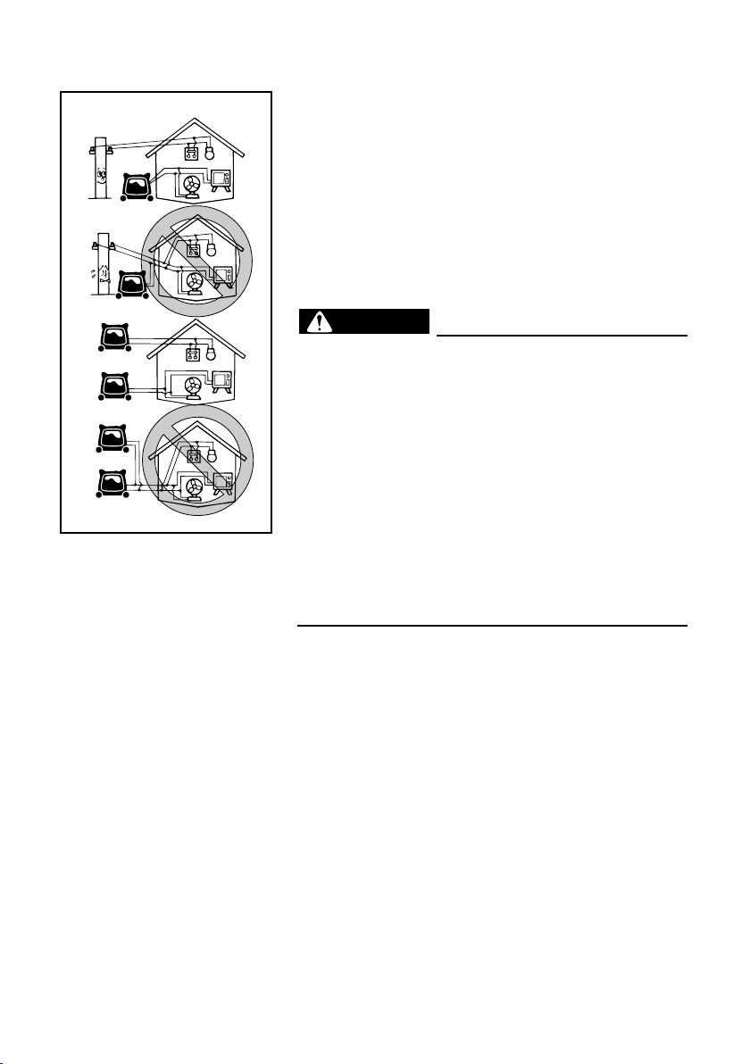
Electric shock prevention......................3
Connection notes..................................4
Connection ...........................................4
Extension cord notes ............................4
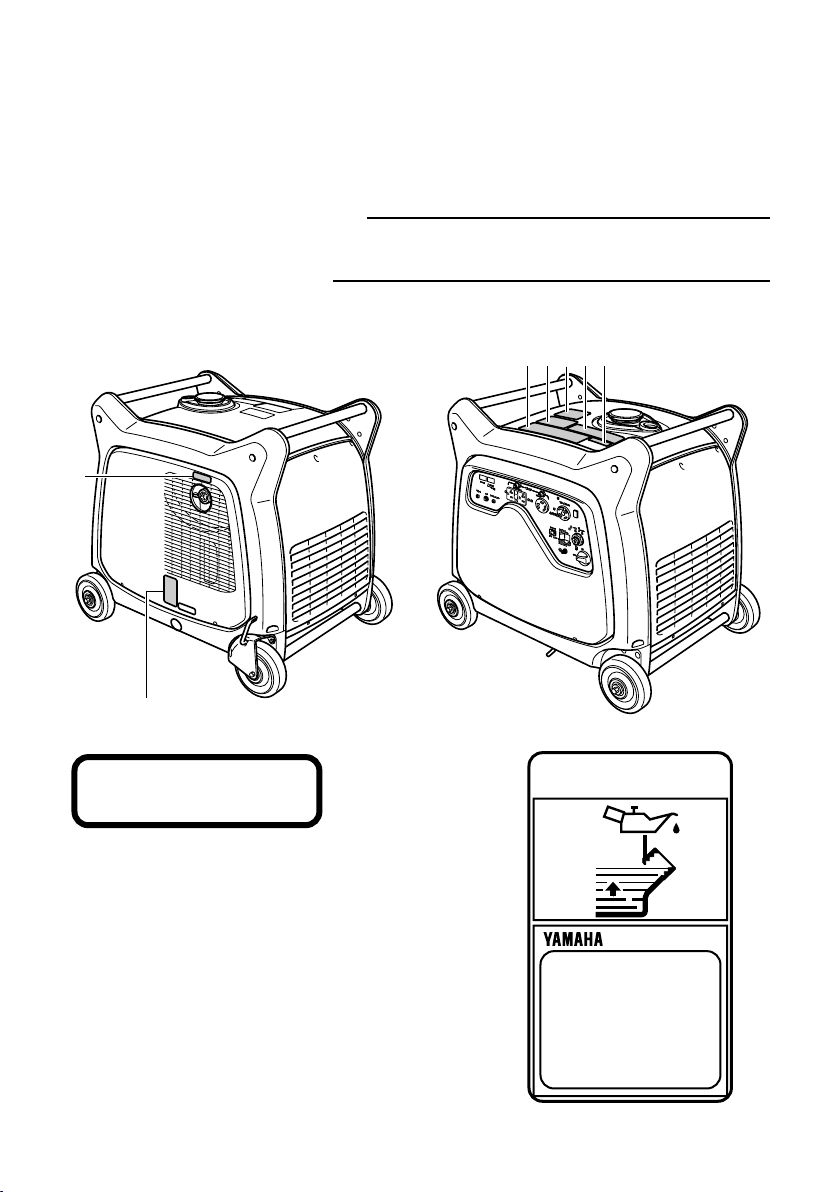
LOCATION OF IMPORTANT
LABELS...................................................5
DESCRIPTION ........................................7
Control panel ........................................7
CONTROL FUNCTION............................8
Engine switch .......................................8
Oil warning light (red) ...........................8
AC protector .........................................9
Economy control switch........................9
G.F.C.I. receptacle .............................10
Voltage select switch ..........................11
Hour meter..........................................12
Power meter .......................................12
AC pilot light (green)...........................12
Overload indicator light (red) ..............13
Fuel tank cap ......................................13
Fuel cock knob ...................................14
Ground (earth) terminal ......................14
Caster lock lever.................................14
PREPARATION.....................................15
Fuel.....................................................15
Engine oil............................................16
Battery preparation .............................17
PRE-OPERATION CHECK ...................19
Pre-operation check ...........................19
OPERATION..........................................20
Starting the engine .............................20
Stopping the engine............................22
Connection .........................................23
Application range................................25
PERIODIC MAINTENANCE ..................27
Maintenance chart ..............................27
Spark plug inspection .........................29
Carburetor adjustment........................31
Engine oil replacement .......................31
Air filter ...............................................32
Muffler screen and spark arrester.......34
Fuel tank filter .....................................36
Battery ................................................37
Recommended battery .......................37
Fuse replacement...............................38
G.F.C.I. receptacle test.......................39
STORAGE .............................................40
Drain the fuel ......................................40
Engine ................................................42
Battery ................................................43
TROUBLESHOOTING ..........................44
SPECIFICATIONS.................................47
Dimensions.........................................47
Engine ................................................47
Generator ...........................................47
Battery ................................................47
CONSUMER INFORMATION................48
Identification number records .............48
Machine identification .........................48
EXHAUST EMISSION CONTROL
SYSTEM AND COMPONENTS.............49
WIRING DIAGRAM ...............................51
YAMAHA MOTOR CORPORATION,
U.S.A.
EF SERIES GENERATORS
3-YEAR LIMITED WARRANTY............53
YAMAHA OUTDOOR POWER
EQUIPMENT
CALIFORNIA EVAPORATIVE
EMISSION CONTROL
WARRANTY STATEMENT ..................56
YAMAHA MOTOR CORPORATION,
U.S.A.
SMALL OFF ROAD ENGINES
CALIFORNIA EMISSION
CONTROL WARRANTY.......................57
YAMAHA EXTENDED SERVICE
(Y.E.S.)..................................................61
7CK-28199-12_a 11.3.21 13:17 Page A-3