EAS20004
HOW TO USE THIS MANUAL
This manual is intended as a handy, easy-to-read reference book for the mechanic. Comprehensive
explanations of all installation, removal, disassembly, assembly, repair and check procedures are laid
out with the individual steps in sequential order.
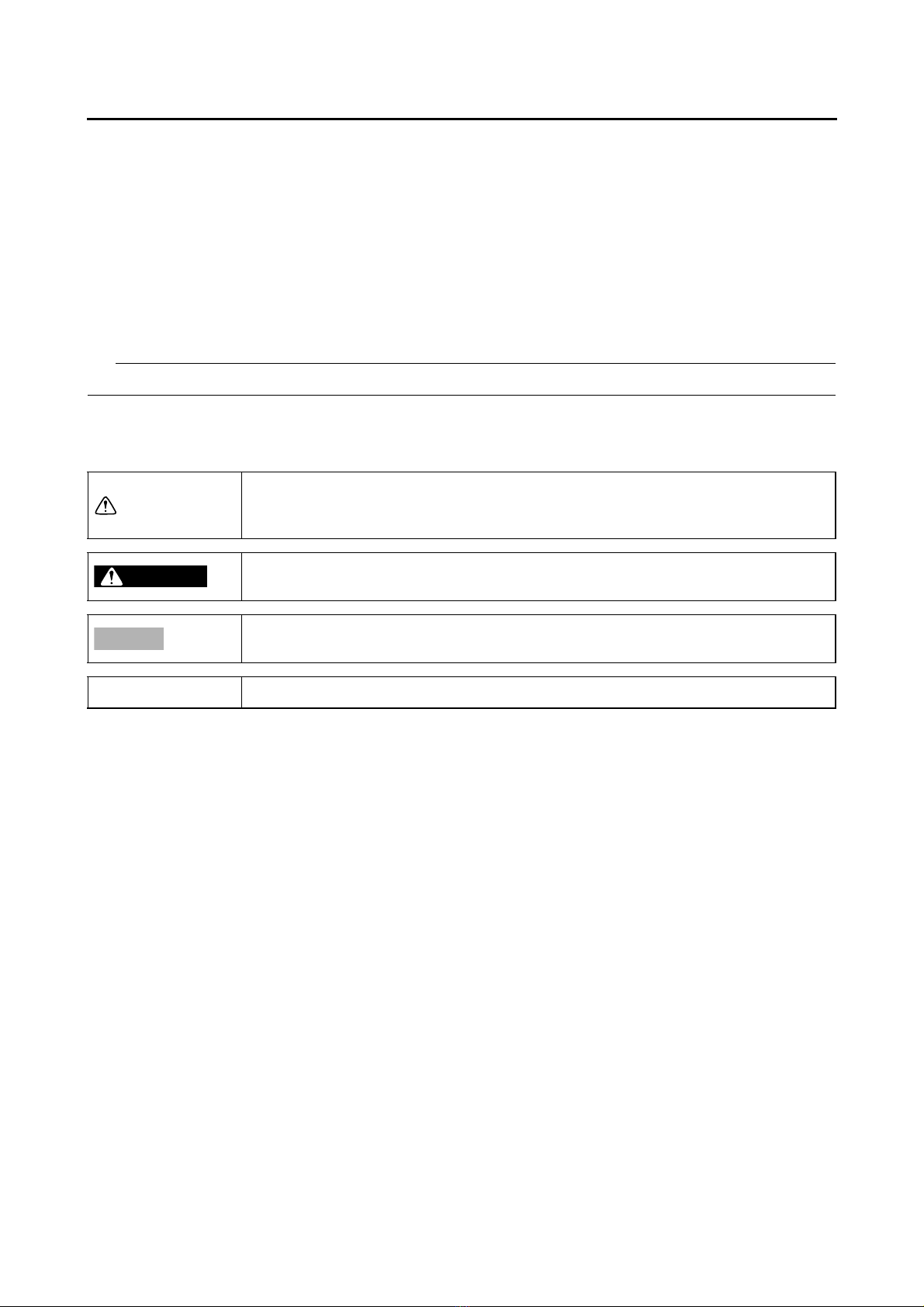
•The manual is divided into chapters and each chapter is divided into sections. The current section title
“1” is shown at the top of each page.
•Sub-section titles “2” appear in smaller print than the section title.
•To help identify parts and clarify procedure steps, there are exploded diagrams “3” at the start of each
removal and disassembly section.
•Numbers “4” are given in the order of the jobs in the exploded diagram. A number indicates a disas-
sembly step.
•Symbols “5” indicate parts to be lubricated or replaced.
Refer to “SYMBOLS”.
•A job instruction chart “6” accompanies the exploded diagram, providing the order of jobs, names of
parts, notes in jobs, etc. This step explains removal and disassembly procedure only. For installation
and assembly procedure, reverse the steps.
•Jobs “7” requiring more information (such as special tools and technical data) are described sequen-
tially.
OIL PUMP
5-59
EAS20054
OIL PUMP
Removing the oil pump assembly
Order Job/Parts to remove Q’ty Remarks
Bottom side cowling/Side panel/Bottom center
cowling
Refer to “GENERAL CHASSIS (1)” on page
4-1.
Center cover/Fuel tank cover assembly/Side
cover (left)/Footboard (left)
Refer to “GENERAL CHASSIS (2)” on page
4-11.
V-belt case air filter element (left)/Generator
cover protector/Water pump inlet pipe/Water
pump outlet pipe/Water pump assembly
Refer to “WATER PUMP” on page 6-9.
Generator cover/Generator rotor/Starter clutch
gear
Refer to “GENERATOR AND STARTER
CLUTCH” on page 5-44.
1ylbmessapmupliO1
1niahcevirdpmupliO2
2teksaG3
1epipyreviledliO4
1epipliO5
1ylbmessaevlavfeileR6
(3)
LT
6
5
3
1
2
4
10 N・m (1.0 kgf・m, 7.4 lb・ft)
10 N・m (1.0 kgf・m, 7.4 lb・ft)
OIL PUMP
5-61
EAS30337
CHECKING THE OIL PUMP
1. Check:
•Oil pump driven gear “1”
•Oil pump housing 2 “2”
•Oil pump housing 1 “3”
Cracks/damage/wear →Replace the oil
pump assembly.
2. Check:
•Oil pump operation
Rough movement →Repeat steps (1) and
(2) or replace the oil pump assembly.
EAS30338
CHECKING THE RELIEF VALVE
1. Check:
•Relief valve body
Damage/wear →Replace.
EAS30742
CHECKING THE OIL PIPES
1. Check:
•Oil pipe
•Oil delivery pipe
Damage →Replace.
Obstruction →Wash and blow out with com-
pressed air.
EAS30785
CHECKING THE OIL PUMP DRIVE CHAIN
1. Check:
•Oil pump drive chain
Cracks/stiffness →Replace the oil pump
chain and oil pump assembly as a set.
EAS30342
ASSEMBLING THE OIL PUMP
1. Lubricate:
•Inner rotor
•Outer rotor
•Oil pump shaft
(with the recommended lubricant)
2. Install:
•Inner rotors
When installing the inner rotor, align the pins “1”
in the oil pump shaft with the grooves “a” in the
inner rotor.
3. Check:
•Oil pump operation
Refer to “CHECKING THE OIL PUMP” on
page 5-61.
EAS30343
INSTALLING THE OIL PUMP
1. Install:
•Oil pump assembly
ECA13890
After tightening the bolts, make sure the oil
pump turns smoothly.
Recommended lubricant
Engine oil
Oil pump bolt
10 N·m (1.0 kgf·m, 7.4 lb·ft)

 Application guide")

 Application guide")


 Application guide")

 Application guide")
 Application guide")


 /LC User manual")