Maselec MDS-2 User manual

MDS-2
Two Channel De-Esser
http://www.maselec.com

MASELEC MDS-2
High Frequency Limiter
Page 2 of 4
DESCRIPTION
The MDS-2 is a dual mono, linkable, high frequency limiter. It is housed in a 1U
19" rack mount alloy case. It is primarily intended for use as a de-esser, reducing
unattractive high frequencies, with minimum coloration and loss of clarity.
Automatic time constants and optimisation techniques for the gain reduction
minimises the number of controls. The advantage is not only simple operation but
also increased performance for highly dynamic and inconsistent materials without
the need for continuous readjustments.
With wide input range, up to +29dBu input and low noise, the MDS-2 can be used
in many different applications.
The side chain can be switched to M-S, which can be used to “zoom” in on high
frequencies in the centre of the stereo image. With this function switched in the
threshold is 6dB lower for the centre image compared to extreme left and right.
The M-S function does not affect the actual audio path.
HF LIMITER
Output frequency response when
the HF limiter is adjusted for max.
high frequency reduction.
4dB reduction: 5msec attack.
10 dB reduction: 1 msec attack
This shows how the attack time
becomes shorter when the high
frequency reduction is increased.

MASELEC MDS-2
High Frequency Limiter
Page 3 of 6
OPERATION
M-S………………….. Switches the side chain inputs to M-S (sum and difference).
LINK…………………. Hard links the side chains after the time constants.
ON…………………… This control enables the high frequency limiter.
FAST………………… This control makes the release time shorter.
HF THRESHOLD……Adjust this control to set the amount of high frequency limiting.
BYPASS………………Galvanic bypass of the unit. The meters show, with reduced
intensity, the gain reduction that would occur if the unit was
not in bypass
The meters show the amount of actual gain reduction (no hold times are incorporated).
Longer release times will be noticed for:
• Frequent limiting over longer time periods
• Large amount of limiting
Note: 0 dB indicates ‘above threshold’.
Optimum reduction of peaks is maintained for extensive variations of programme
materials. When longer release times are noticed, additional reduction of short
duration peaks will still only cause short, programme dependent, release times.
The result is predictable and consistent performance over a wide dynamic range.
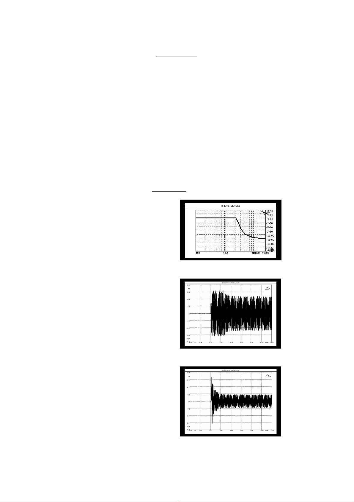
The HF limiter has a maximum range of 11dB starting at approximately 2kHz.
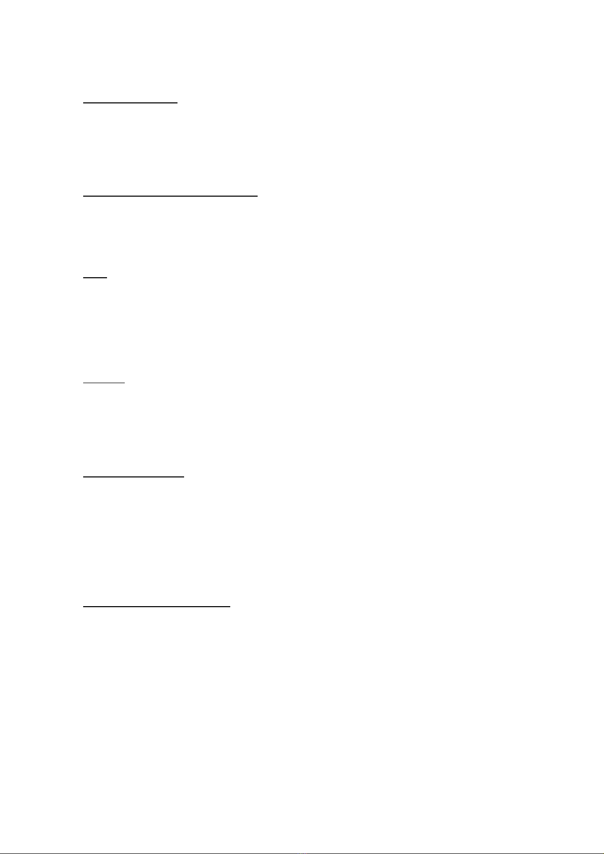
The attack time is both programme dependent and non-linear relative to the
amount of limiting taking place. It is long for small amounts of HF limiting
(>20msec) and becomes progressively faster for more limiting (<1msec). This acts
as a barrier for HF limiting near or just above the threshold and increases
selectivity.
The M-S control will further increase the selectivity for programmes with excessive
treble in the centre of the stereo image. This is normally the case when de-essing
vocals.
Switching to M-S will reduce HF limiting from ‘stereo’ signals whilst retaining the
limiting on centre signals.
The M-S mode does not affect the actual audio path!

MASELEC MDS-2
High Frequency Limiter
Page 4 of 6
INSTALLATION
Caution: Make sure that the rear panel mounted voltage selector is set to correct voltage!
• Connect inputs and outputs to XLR connectors using high quality cables only.
• Both inputs and outputs are balanced.
• For unbalanced connections either pin 2 or pin 3 should be terminated to audio ground.
• Always connect audio screens to pin 1.
• Do not place the MDS-2 near or above other units producing excessive heat or electro-
magnetic fields.
Changing the setup for Low Levels
In recording and mixing the levels can be too low for the MDS-2 to fully change high frequencies.
A switch located inside the unit adds +14dB gain in the side chains for increased sensitivity.
1. Disconnect the mains lead. Failing to do so would be seriously dangerous.
2. Take the top lid off by removing six screws.
3. Locate the slide switch at the centre of the pcb marked “THRESHOLD”.
4. Switch it to “LOW”
5. Put the lid back on and replace the six screws.
6. Connect the mains lead.
7. Done!

MASELEC MDS-2
High Frequency Limiter
Page 5 of 6
SPECIFICATION
Input dynamic Range......................... Better than 120dB
Output dynamic range........................Better than 120dB
Maximum input level..........................129dBu (balanced)
Maximum output level........................129dBu (balanced)
Distortion............................................Typically less than 0.003%
HF limiter attack time......................... Programme dependent 1msec to 20msec
Release time......................................Programme dependent
Input impedance................................ 100k
Ω
ground floating electronically balanced
Output impedance............................. 33
Ω
electronically balanced
Threshold...........................................-26dB to +∞(low: -40dB to +∞)
Gain...................................................0dB
H.F. Limiter........................................>2kHz
Power.................................................90-130, 180-260 Volts @ 50-60 Hz
Fuse...................................................315mA, anti surge (slow)
Subject to change without notice.

MASELEC MDS-2
High Frequency Limiter
Page 6 of 6
Servicing and repair
There are no user serviceable parts inside this unit.
Repairs should only be undertaken by qualified electronics technicians or engineers.
Mains transformer voltage selection
The mains transformer has a tapped primary to allow operation at nominal voltages of 115V
or 230V. Ensure that the correct voltage range is selected before using the MLA-2.
Fuse
There is one mains fuse, accessible externally in the IEC320 mains inlet. If this fuse is
blown it should be replaced by a similar value and type.
20x5mm 250V 315mAT (antisurge, slow)
Earthing
The unit has an internal link connecting the audio ground to the chassis.
A chassis earth stud is provided on the rear of the unit.
Physical dimensions
Weight: 4kg
Width: 19 inch (483mm) rack-mountable
Height: 1U (44mm)
Depth: 10.25 inches (260mm) add clearance for connectors
Electromagnetic Compatibility
This equipment is intended for use in an electromagnetically controlled environment.
To maintain the performance specification it should not be subject to strong magnetic fields
(such as in the immediate vicinity of a power amplifier or cathode ray tube)
This equipment does not include digital circuitry (or generate high frequencies)
that could be radiated or conducted from the unit.
Table of contents
Other Maselec Music Equipment manuals
Popular Music Equipment manuals by other brands

Sweet Sound Electronics
Sweet Sound Electronics Mojo Vibe instruction manual

Behringer
Behringer ULTRA-DI DI100 user manual

Alesis
Alesis QuadraVerb 2 user guide

Pyle
Pyle PHST90 owner's manual

Panasonic
Panasonic RS-805US Service manual

Digital Audio Corporation
Digital Audio Corporation PikoDAC PDAC256 user manual