10
DIAGNOSIS AND MAINTENANCE
Oneofthemostimportantstepsinahighpressuresystemistoestablisharegularmaintenanceprogram.This
willvaryslightlywitheachsystemandisdeterminedbyvariouselementssuchasthedutycycle,theliquidbeing
pumped,theactualspecificationsvsratedspecificationsofthepump,theambientconditions,theinletconditions
andtheaccessoriesinthesystem.Acarefulreviewofthenecessaryinletconditionsandprotectiondevicesrequired
beforethesystemisinstalledandeliminatemanypotentialproblems.
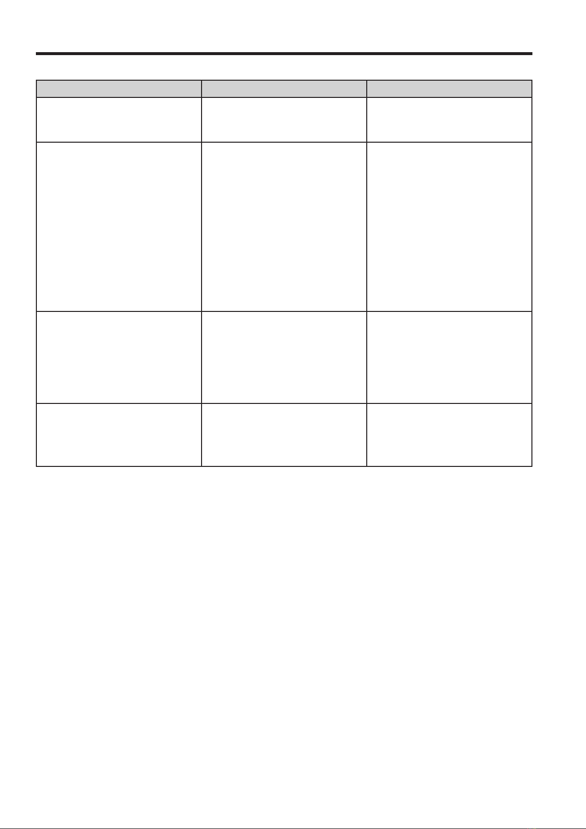
PROBLEM PROBABLE CAUSE SOLUTION
Low pressure Wornnozzle.
Airleakinletplumbing.
Pressuregaugeinoperativeornot
registeringaccurately.
Reliefvalvestuck,partiallypluggedor
improperlyadjusted.
Inletsuctionstrainer(filter)cloggedor
improperlysized.
Abrasivesinpumpedliquid.
Leakydischargehose.
Inadequatewatersupply.
Severecavitation.
WornSeals.
Wornordirtyinlet/dischargevalves.
Replacewithproperlysizednozzle.
Tightenfittingsandhoses.UsePTFE
liquidortape.
Checkwithnewgauge.Replaceworn
ordamagedgauge.
Clean/adjustreliefvalve.Replace
worn/seatsando-rings.
Cleanfilter.Useadequatesizefilter.
Checkmorefrequently.
Installproperfilter.
Replacedischargehosewithproper
ratingforsystem.
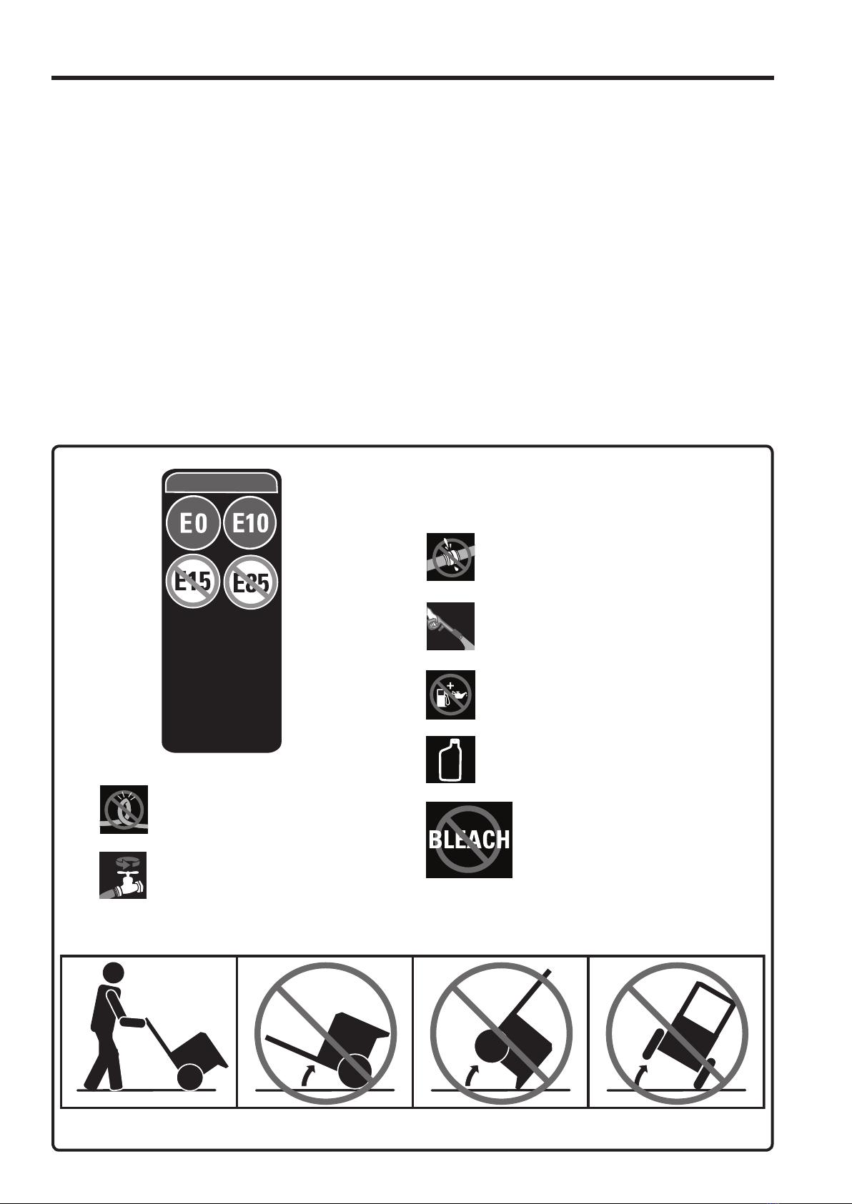
Inadequatewatersupply,minimum
35PSIandhosesize3/4”-5/8”.
Checkinletconditions
Installnewsealkit.Increase
frequencyofservice.
Cleaninlet/dischargevalvesorinstall
newvalvekit.
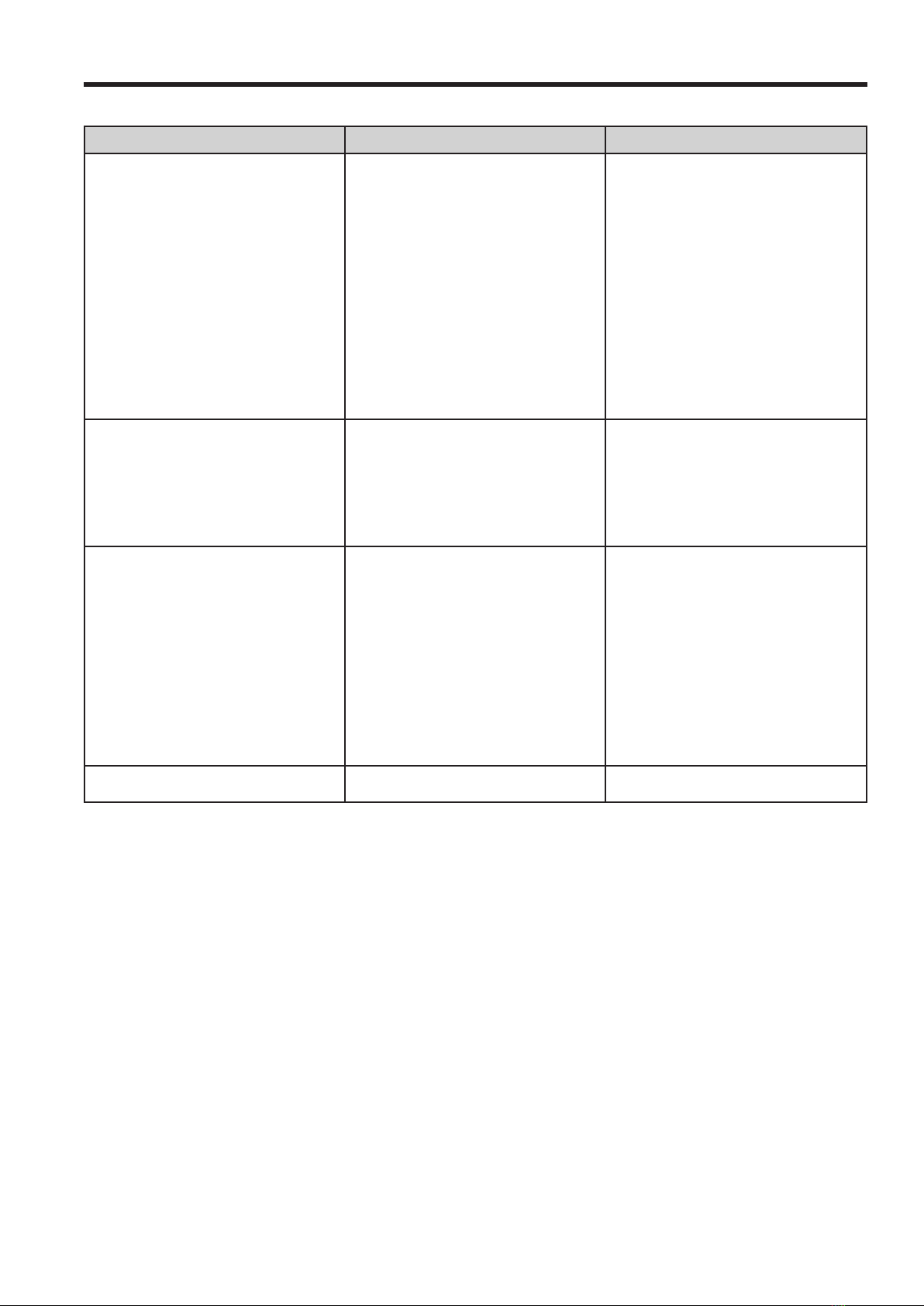
Pulsation Inadequatewatersupply.
Foreignmaterialtrappedininlet/
dischargevalves.
Inadequatewatersupply,minimum
35PSIandhosesize3/4”-5/8”.
Cleaninlet/dischargevalvesorinstall
newvalvekit.
Water leak
Underthemanifold.
Intothecrankcase.
WornV-Packing,Hi-Pressureor
Lo-PressureSeals
Wornadaptero-rings.
Excessiveweartoseals.
Installnewsealkit.Increase
frequencyofservice.
Installnewo-rings.
Installnewsealkit.Increase
frequencyofservice.
Kocking noise
Inletsupply.
Bearing.
Inadequatewatersupply.
Brokenorwornbearing.
Inadequatewatersupply,minimum
35PSIandhosesize3/4”-5/8”.
Replacebearing.