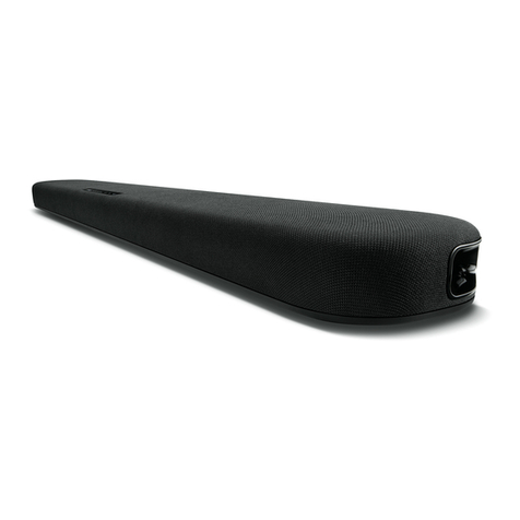
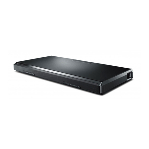
Yamaha YSP-1600 User manual

IMPORTANT NOTICE
This manual has been provided for the use of authorized Yamaha Retailers and their service personnel.
It has been assumed that basic service procedures inherent to the industry, and more specifically Yamaha Products, are already known
and understood by the users, and have therefore not been restated.
WARNING: Failure to follow appropriate service and safety procedures when servicing this product may result in personal injury,
destruction of expensive components, and failure of the product to perform as specified. For these reasons, we advise
all Yamaha product owners that any service required should be performed by an authorized Yamaha Retailer or the
appointed service representative.
IMPORTANT: The presentation or sale of this manual to any individual or firm does not constitute authorization, certification or
recognition of any applicable technical capabilities, or establish a principle-agent relationship of any form.
The data provided is believed to be accurate and applicable to the unit(s) indicated on the cover. The research, engineering, and service
departments of Yamaha are continually striving to improve Yamaha products. Modifications are, therefore, inevitable and specifications
are subject to change without notice or obligation to retrofit. Should any discrepancy appear to exist, please contact the distributor's
Service Division.
WARNING: Static discharges can destroy expensive components. Discharge any static electricity your body may have
accumulated by grounding yourself to the ground buss in the unit (heavy gauge black wires connect to this buss).
IMPORTANT: Turn the unit OFF during disassembly and part replacement. Recheck all work before you apply power to the unit.
SERVICE MANUAL
■CONTENTS
TO SERVICE PERSONNEL ............................................2
PANEL LAYOUTS .......................................................3–5
REMOTE CONTROL PANELS .......................................6
SPECIFICATIONS / 参考仕様 .....................................7–9
INTERNAL VIEW .......................................................... 10
SERVICE PRECAUTIONS / サービス時の注意事項 ..... 10
DISASSEMBLY PROCEDURES / 分解手順 ........... 11–18
WRITING DESTINATION / 仕向け先の書き込み ..... 19–24
PROTECTION DISPLAY / プロテクションの表示 ........25
SELF-DIAGNOSTIC FUNCTION /
ダイアグ(自己診断機能)
.....................................26–51
IC DATA ...................................................................52–57
PIN CONNECTION DIAGRAMS .............................58–59
BLOCK DIAGRAMS ................................................60–61
WIRING DIAGRAMS ...............................................62–63
PRINTED CIRCUIT BOARDS .................................64–70
SCHEMATIC DIAGRAMS .......................................71–77
REPLACEMENT PARTS LIST ................................79–97
REMOTE CONTROL ...............................................98–99
UPDATING THE UNIT’S FIRMWARE ......................... 100
本機のファームウェアを更新する ............................... 101
DIGITAL SOUND PROJECTOR
P.O.Box 1, Hamamatsu, Japan
'15.10
Copyright (c) Yamaha Corporation All rights reserved.
This manual is copyrighted by Yamaha and may not be copied or
redistributed either in print or electronically without permission.
101346
YSP-1600
YSP-1600
DRAFT

1. Critical Components Information
Components having special characteristics are marked and
must be replaced with parts having specifications equal to those
originally installed.
2. Leakage Current Measurement (For 120V Models Only)
When service has been completed, it is imperative to verify
that all exposed conductive surfaces are properly insulated
from supply circuits.
• Meter impedance should be equivalent to 1500 ohms shunted
by 0.15 μF.
■TO SERVICE PERSONNEL
• Leakage current must not exceed 0.5mA.
• Be sure to test for leakage with the AC plug in both polarities.
WALL
OUTLET EQUIPMENT
UNDER TEST
AC LEAKAGE
TESTER OR
EQUIVALENT
INSULATING
TABLE
注意:
All of the P.C.B.s installed in this unit and solder joints are
soldered using the lead free solder.
Among some types of lead free solder currently available,
it is recommended to use one of the following types for
the repair work.
• Sn + Ag + Cu (tin + silver + copper)
• Sn + Cu (tin + copper)
• Sn + Zn + Bi (tin + zinc + bismuth)
Caution:
As the melting point temperature of the lead free solder
is about 30°C to 40°C (50°F to 70°F) higher than that of
the lead solder, be sure to use a soldering iron suitable
to each solder.
About lead free solder / 無鉛ハンダについて
For U model
“CAUTION”
“F701: FOR CONTINUED PROTECTION AGAINST RISK OF FIRE, REPLACE ONLY WITH SAME TYPE 5A, 125V
FUSE.”
For C model
CAUTION
F701: REPLACE WITH SAME TYPE 5A, 125V FUSE.
ATTENTION
F701: UTILISER UN FUSIBLE DE RECHANGE DE MÉME TYPE DE 5A, 125V.
CALIFORNIA PROPOSITION 65 WARNING
This product contains chemicals known to the State of California to cause cancer, or birth defects or other reproductive
harm.
DO NOT PLACE SOLDER, ELECTRICAL/ELECTRONIC OR PLASTIC COMPONENTS IN YOUR MOUTH FOR ANY REASON
WHAT SO EVER!
Avoid prolonged, unprotected contact between solder and your skin! When soldering, do not inhale solder fumes or
expose eyes to solder/flux vapor!
If you come in contact with solder or components located inside the enclosure of this product, wash your hands before
handling food.
2
YSP-1600
YSP-1600
DRAFT

U, C, T, K, A, B, G, L, V, S models
J model
U, C, T, K, A, B, G, L, V, S models
J model
Top view
Front view
Rear view
Bottom view
Labels
■PANEL LAYOUTS
3
YSP-1600
YSP-1600
DRAFT

U, C models
T model
K model
A model
Labels
4
YSP-1600
YSP-1600
DRAFT

B, G models
L model
V, S models
J model
5
YSP-1600
YSP-1600
DRAFT

■REMOTE CONTROL PANELS
FSR86
(U, C, T, K, A, B, G, L, V, S models)
FSR87
(J model)
6
YSP-1600
YSP-1600
DRAFT

■Amplifier Section / アンプ部
Rated RMS Output Power / 定格出力 (1 % THD)
TWEETER (1 kHz, 4 ohms) ........................................ 13.6 W/ch
SUBWOOFER (100 Hz, 3 ohms).................................... 48 W/ch
Maximum Effective Output Power /
実用最大出力
(10 % THD)
TWEETER (1 kHz, 4 ohms) ............................................ 2 W x 8
SUBWOOFER (100 Hz, 3 ohms)................................... 30 W x 2
Total Harmonic Distortion / 全高調波歪率 (20 k L.P.F.)
Digital Input
TWEETER (1 kHz, 1.0 V/6 ohms) .......................0.08 % or less
SUBWOOFER (100 Hz, 4.0 V/3 ohms) ..............0.05 % or less
Signal to Noise Ratio / 信号対雑音比 (IHF-A weighted)
Digital Input
SUBWOOFER (100 Hz, 12.4 V/3 ohms) ........... 98 dB or more
Analog Input
SUBWOOFER (100 Hz, 12.4 V/3 ohms) ........... 85 dB or more
Maximum Input Signal / 最大許容入力
Analog Input
.......................................................................2.2 Vrms or less
Subwoofer Output / サブウーファー出力
Level / レベル (150 Hz or less)
..........................................................................1.6 ±0.2 Vrms
Impedance / インピーダンス
...............................................................................1.4 k-ohms
■Speaker Section / スピーカー部
Type / 型式
TWEETER ............................ Acoustic suspension type /
SUBWOOFER ..............................Bass reflex type /
Driver / スピーカーユニット
TWEETER (Full-range)
.................. 2.8 cm (1-1/8") cone magnetic shielding type x 8
SUBWOOFER
........... 8.5 cm (3-3/8") cone non-magnetic shielding type x 2
Frequency Response / 再生周波数帯域
TWEETER ........................................................500 Hz to 22 kHz
SUBWOOFER ...................................................50 Hz to 500 Hz
Impedance / インピーダンス
TWEETER ........................................................................4 ohms
SUBWOOFER .................................................................6 ohms
■Bluetooth Section / Bluetooth 部
Bluetooth Version / Bluetooth バージョン
..............................................................................Ver. 2.1+EDR
Supported Profile / 対応プロファイル
...................A2DP (Advanced audio distribtion profile), AVRCP
Supported Audio CODEC / 対応コーデック
Receiving ......................................................SBC, MPEG4 AAC
Transmitting ......................................................................... SBC
■SPECIFICATIONS /
参考仕様
RF Output Power / 無線出力
........................................................................Bluetooth class 2
Maximum Communication Range / 最大通信距離
.............................................................................10 m (32.8 ft.)
(without obstructions / )
Supported Contents Protection / 対応コンテンツ保護
.......................................................SCMS-T (receiving) method
■General / 総合
Power Supply / 電源電圧
U, C models ..................................................... AC 120 V, 60 Hz
T model ............................................................ AC 220 V, 50 Hz
K, A, B, G, L, S models ....................... AC 220–240 V, 50/60 Hz
V model ............................................... AC 110–120 V, 50/60 Hz
J model ....................................................... AC 100 V, 50/60 Hz
Power Consumption / 消費電力
........................................................................................... 25 W
Standby Power Consumption / 待機時消費電力
HDMI control OFF, Network standby OFF
....................................................................................... 0.4 W
HDMI control ON, Network standby OFF
....................................................................................... 1.5 W
HDMI control OFF, Network standby ON
Wired .............................................................................. 1.9 W
Wi-Fi ............................................................................... 1.8 W
Wireless direct ................................................................ 2.0 W
Bluetooth ........................................................................ 1.9 W
HDMI control ON, Network standby ON
....................................................................................... 3.0 W
Dimensions (W x H x D) / 寸法(幅×高さ×奥行き)
Without antenna / アンテナを含まない
...................... 1,000 x 65 x 130 mm (39-3/8" x 2-1/2" x 5-1/8")
With antenna / アンテナを含む
.......................... 1,000 x 134 x 152 mm (39-3/8" x 5-1/4" x 6")
Weight / 質量
........................................................................ 4.7 kg (10.4 lbs.)
Finish / 仕上げ
U, C, T, K, A, B, G, L, V, S, J models ........................ Black color
T, B, G, L, J models ...................................................Silver color
Accessories / 付属品
Remote control .......................................................................x 1
Battery (R03, AAA, UM-4) ......................................................x 2
Optical cable (1.5 m) .............................................................x 1
Bracket (30 x 48.5 x 29 mm) ..................................................x 2
PW head screw (M4 x 12 mm) ...............................................x 4
Mounting template (1,040 x 134 mm) ....................................x 1
*Specifications are subject to change without notice.
※ 参考仕様および外観は、製品の改良のため予告なく変更する
ことがあります。
7
YSP-1600
YSP-1600
DRAFT

MusicCast is a trademark or registered trademark of Yamaha Corporation.
MusicCast はヤマハ株式会社の登録商標です。
DLNA™ and DLNA CERTIFIED™ are trademarks or registered trademarks
of Digital Living Network Alliance. All rights reserved.
Unauthorized use is strictly prohibited.
DLNA™および DLNACERTIFIED™はデジタルリビングネットワークアライアン
スの登録商標です。
無断使用は固く禁じられています。
The Wi-Fi CERTIFIED Logo is a certification mark of Wi-Fi Alliance.
The Wi-Fi Protected Setup Identifier Mark is a certification mark of Wi-Fi
Alliance.
Wi-Fi, Wi-Fi Alliance, Wi-Fi CERTIFIED, Wi-Fi Protected Setup, WPA and
WPA2 are trademark or registered trademark of Wi-Fi Alliance.
Wi-FiCERTIFIED ロゴは Wi-FiAlliance の認証マークです。
Wi-FiProtectedSetup のマークは Wi-FiAlliance の認証マークです。
Wi-Fi、Wi-FiAlliance、Wi-FiCERTIFIED、Wi-FiProtectedSetup、WPA、WPA2
は Wi-FiAlliance の商標または登録商標です。
Copyright 1999-2014 OpenSynergy GmbH
All rights reserved. All unpublished rights reserved.
AAC ロゴマークはドルビーラボラトリーズの商標です。
ラジコ /radiko および radiko ロゴは株式会社 radiko の登録商標です。
Windows is a registered trademark of Microsoft Corporation in the United
States and other countries.
Windows は米国 MicrosoftCorporation の米国およびその他の国における登録商
標です。
Android is a trademark of Google Inc.
Android は、GoogleInc. の商標または登録商標です。
The “ ” logo and “Cinema DSP” are registered trademarks of
Yamaha Corporation.
「シネマ DSP」「CINEMADSP」は、ヤマハ株式会社の登録商標です。
Manufactured under license from Dolby Laboratories.
Dolby, Pro Logic, and the double-D symbol are trademarks of Dolby
Laboratories.
ドルビーラボラトリーズからの実施権に基づき製造されています。
Dolby、ドルビー、ProLogic 及びダブル D 記号はドルビーラボラトリーズの商
標です。
For DTS patents, see http://patents.dts.com. Manufactured under license
from DTS Licensing Limited.
DTS, the Symbol, & DTS and the Symbol together are registered trademarks,
and DTS Digital Surround is a trademark of DTS, Inc.
© DTS, Inc. All Rights Reserved.
DTS の特許に関しては http://patents.dts.com をご覧ください。本製品は DTS
LicensingLimited のライセンスに基づき製造しています。
DTS、そのシンボルマークおよび DTS とそのシンボルマークの組み合せは、DTS
社の登録商標です。DTSDigitalSurround は DTS,Inc. の商標です。
©DTS,Inc.AllRightsReserved.
“HDMI,” the “HDMI” logo and “High-Definition Multimedia Interface” are
trademarks, or registered trademarks of HDMI Licensing LLC.
HDMI、HDMI ロゴ、および High-DefinitionMultimediaInterface は、HDMI
Licensing,LLC の商標または登録商標です。
“x.v.Color” is a trademark of Sony Corporation.
「x.v.Color」はソニー株式会社の商標です。
The Bluetooth® word mark and logos are registered trademarks owned by
Bluetooth SIG, Inc. and any use of such marks by Yamaha Corporation is
under license.
Bluetooth® およびロゴは Bluetooth SIG の登録商標であり、ヤマハ株式会社はラ
イセンスに基づき使用しています。
“Blu-ray Disc™”, “Blu-ray™”, and the logos are trademarks of the Blue-
ray Disc Association.
「ブルーレイ™」および「ブルーレイディスク™」はブルーレイディスクアソ
シエーションの商標です。
iTunes, AirPlay, iPad, iPhone, iPod, and iPod touch are trademarks of
Apple Inc., registered in the U.S. and other countries.
iTunes、AirPlay、iPad、iPhone、iPod、iPodtouch は、米国およびその他の国々
で登録されている AppleInc. の商標です。iPhone 商標は、アイホン株式会
社のライセンスに基づき使用されています。
Internet Explorer, Windows Media Audio and Windows Media Player are
either registered trademarks or trademarks of Microsoft Corporation in
the United States and/or other countries.
InternetExplorer、WindowsMediaAudio、WindowsMediaPlayer は、米国
MicrosoftCorporation の米国およびその他の国における登録商標、または
商標です。
U .......................U.S.A. model
C .................Canadian model
T .................... Chinese model
K .....................Korean model
A ................Australian model
B ......................British model
G .................European model
L .................Singapore model
V ....................General model
S .................. Brazilian model
J .................. Japanese model
8
YSP-1600
YSP-1600
DRAFT

270 (10-5/8")
197 (7-3/4")
1000 (39-3/8")
1000 (39-3/8")
3
(1/8")
62
(2-3/8")
65 (2-1/2")
134 (5-1/4")
52
(2")
156 (6-1/8")
152 (6")
130 (5-1/8")
457 (18")
13.6 (1/2")500 (19-5/8")
112.5 (4-3/8")
68.4
(2-5/8")
65
(2-1/2")
51.8 (2")
1.2
1.5–2.5
min 20 (3/4")
ø7–8.5
ø4
Wall mount setting with spacer / 壁掛け設置スペーサー含む
In front of TV placing / テレビ 前 置き設 置
Side view
Without antenna / アンテナを含む
With antenna / アンテナを含まない
Without antenna / アンテナを含む
With antenna / アンテナを含まない
Top view
Front view
Rear view
Top view
Front view
Rear view
•DIMENSIONS /
寸法図
Unit: mm (inch)
単位:mm(インチ)
9
YSP-1600
YSP-1600
DRAFT

INPUT P.C.B.
MAIN P.C.B.
POWER (7) P.C.B.
POWER (1) P.C.B.
DRIVER SUBWOOFER
NETWORK MODULE
OPERATION (3) P.C.B.
OPERATION (1) P.C.B.
DRIVER TWEETER
POWER (4) P.C.B.
POWER (2) P.C.B.
POWER (5) P.C.B.
POWER (6) P.C.B.
89 1110
1
2
3
4
5
6
7
8
9
10
11
12
13
12 43
765 5
12 13
Top view
Front view
Rear view
■INTERNAL VIEW
■SERVICE PRECAUTIONS / サービス時の注意事項
安全対策
Safety measures
• Some internal parts in this product contain high voltages
and are dangerous.
Be sure to take safety measures during servicing, such
as wearing insulating gloves.
• Note that the capacitors indicated below are dangerous
even after the power is turned off because an electric
charge remains and a high voltage continues to exist
there.
Before starting any repair work, connect a discharging
resistor (5 k-ohms/10 W) to the terminals of each
capacitor indicated below to discharge electricity.
The time required for discharging is about 30 seconds
per each.
C713, C728 and C730 on POWER (1) P.C.B.
For details, refer to “PRINTED CIRCUIT BOARDS”.
計測機器取り扱い上の注意
Precaution for handling measuring instrument
Since the speaker output of this unit is BTL connected, the
ground side of the measuring instrument to be connected
to the speaker terminal MUST be kept in floating condition.
10
YSP-1600
YSP-1600
DRAFT

Fig. 1
■DISASSEMBLY PROCEDURES / 分解手順
1. IR バーの外し方(Fig.1)
IR バーの長さ
(Remove parts in the order as numbered.)
Disconnect the power cable from the AC outlet.
1. Removal of IR Bar (Fig. 1)
a. Spread a rubber sheet and cloth for protection of this
unit against any damage and place this unit on cloth
with its bottom cover facing up.
b. Remove the dipole antenna.
c. Remove 8 screws ().
d. Remove the IR bar A, IR bar B and IR bar C.
Length of the IR bar
IR bar A: 105.06 mm (4-1/8")
IR bar B: 141.56 mm (5-5/8")
IR bar C: 281.4 mm (11-1/8")
*When installing the IR bar A, IR bar B and IR bar C,
be careful to fit them in correct position and direction.
If that is not installed properly, the relay function of
the TV remote control may fail to operate accurately.
IR bar A
IR バー A
IR bar B
IR バー B
IR bar C
IR バー C
IR bar C
IR バー C
Rubber sheet and the cloth
ゴムシートと布
Dipole antenna
ダイポールアンテナ
Bottom cover
ボトムカバ ー
①
①
①
①
11
YSP-1600
YSP-1600
DRAFT

③
Ruber sheet and the cloth
ゴムシートと布
CB801
POWER (5) P.C.B.
④
②
②
③
③
③
③③
③
②
③
③
CB802
POWER (6) P.C.B.
③
③
③
Top cover assembly
トップカバー Ass'y
Bottom cover assembly
ボトムカバー Ass'y
SUBWOOFER cable
サブウーファーケーブ ル
Connectors
コネクター
2. Removal of Bottom Cover Assembly (Fig. 2)
a. Remove 4 screws (), 32 screws () and 2 screws
().
b. Disconnect the connector connected to the terminal
of the driver (SUBWOOFER).
c. Remove CB801 and CB802.
d. Remove the bottom cover assembly.
2. ボトムカバー Ass'y の外し方(Fig.2)
Fig. 2
12
YSP-1600
YSP-1600
DRAFT

3. Removal of Amp Unit (Fig. 3)
a. Detach the insulator attached to the shield top (L, R)
and loosen the fixed cable.
b. Remove hexagonal nut and then remove the antenna
cable.
c. Remove 2 screws ().
d. Remove CB831.
e. Remove the OPERATION (1) P.C.B.
f. Remove 4 screws (), 10 screws (), 3 screws ()
and 8 screws ().
g. Remove the shield top L and shield top R.
h. Remove 6 screws ().
i. Remove 3 screws () and then remove the wire
clamp.
j. Remove the packing and 2 bushings.
k. Remove CB701 and CB903.
l. Remove the amp unit.
3. アンプユニットの外し方(Fig.3)
Fig. 3
⑤
⑩
CB831
CB701
CB903
⑦
⑦
⑨
⑨
⑦
⑥
⑪
⑧
⑨
⑦
⑦
⑨
Bottom cover unit
ボトムカバーユニット
Shield top L
シ−ルドトップ L
Shield top R
シ−ルドトップ R
Amp unit
アンプ ユ ニット
Wire clamp
ワイヤークランプ
OPERATION (1) P.C.B.
POWER (1) P.C.B.
MAIN P.C.B.
Antenna cable
アンテナ同軸ケーブル
Hexagonal nut
六角ナット
Packing
パッキン
Bushings
ブッシュ
13
YSP-1600
YSP-1600
DRAFT

Fig. 4
4. Removal of OPERATION (3) P.C.B. (Fig. 4)
a. Remove 2 screws ().
b. Remove the OPERATION (3) P.C.B. to upward.
The OPERATION (3) P.C.B. is directly connected to
the INPUT P.C.B. and MAIN P.C.B. with the board-to-
board connectors.
5. Removal of MAIN P.C.B. (Fig. 4)
a. Remove 6 screws ().
b. Remove CB901, CB902, CB905 and CB906.
c. Remove the MAIN P.C.B.
6. Removal of POWER (1) P.C.B. (Fig. 4)
a. Remove 6 screws ().
b. Remove the POWER (1) P.C.B.
4. OPERATION(3)P.C.B. の外し方(Fig.4)
5. MAINP.C.B. の外し方(Fig.4)
6. POWER(1)P.C.B. の外し方(Fig.4)
POWER (1) P.C.B.
MAIN P.C.B.
CB905
CB902
CB906
CB972
CB910
CB901
CB971
CB601
INPUT P.C.B.
⑭
⑬
⑫
⑫OPERATION (3) P.C.B.
14
YSP-1600
YSP-1600
DRAFT

7. Removal of Network Module
a. Remove 6 screws (). (Fig. 5)
b. Remove the input cover A. (Fig. 5)
c. Remove 2 screws (). (Fig. 5)
d. Remove the heatsink and the thermal sheet. (Fig. 5)
e. Remove the wireless LAN antenna connector by
using MHF connector remover.
f. Remove 2 screws (). (Fig. 5)
g. Remove the network module together with the support
frame to upward. (Fig. 5)
The network module is directly connected to the
INPUT P.C.B. with the board-to-board connectors.
7. ネットワークモジュールの外し方
注意!
CAUTION !
• To remove the wireless LAN antenna connector, use
the special MHF connector remover. Hook the tip of
this tool on the cover of the wireless LAN antenna
connector and pull it straight in the direction of the
engaging axis of the wireless LAN antenna connector.
(Fig. 6)
Special removing tool
ZK708100: MHF connector remover
Fig. 6
Fig. 5
Wireless LAN antenna connector
無線 LAN アンテナコネクター
Input cover A
インプットカバー A
Network module
ネットワークモジュー ル
Amp unit
アンプ ユ ニット
Heatsink
ヒートシンク
Thermal sheet
熱伝導シート
Support frame
サポートフレーム
CB201
⑯
⑰
⑮
⑮⑮
MHF connector remover
MHF コネクター挿抜工具
Wireless LAN antenna connector
無線 LAN アンテナコネクター
15
YSP-1600
YSP-1600
DRAFT

Fig. 7
• The wireless LAN antenna connector should only be
plugged back to the network module after it has been
installed back onto the INPUT P.C.B.
• When plugging the wireless LAN antenna connector
back to the network module, make sure to hold it and
insert it vertically using the MHF connector remover.
Make sure not to insert the wireless LAN antenna
connector at a sharp angle as it may break.
• The wireless LAN antenna connector can be inserted
and removed up to 5 times only.
8. Removal of INPUT P.C.B. (Fig. 7)
a. Remove 2 screws (), 2 screws () and 2 screws ().
b. Remove the INPUT P.C.B.
8. INPUTP.C.B. の外し方(Fig.7)
INPUT P.C.B.
⑱
⑲
⑳
⑳
16
YSP-1600
YSP-1600
DRAFT

㉔
㉔
㉑
㉕
㉓
㉒
Cabinet
キャビネット
Cabinet cap
キャビネットキャップ
Cabinet cap
キャビネットキャップ
Front grille assembly
フロントグリル Ass'y
Tweeters
ツィーター
CB905
CB906
Fig. 9
Fig. 8
Installation of Tweeters
Note: Make sure that all the removed tweeters are
reinstalled at specified positions. (Fig. 9)
ツィーターの取り付け方
注意:
Pin No. (Cable color) CB905 CB906
ピン番号(線色)
1: (Black), 2: (Red) T05 T04
3: (Black), 4: (Green) T06 T03
5: (Black), 6: (Yellow) T07 T02
7: (Black), 8: (Orange) T08 T01
9: (N.C.) No use
9. Removal of Tweeters
a. Remove 4 screws (), 3 screws () and 7 screws ().
(Fig. 8)
b. Remove the front grille assembly. (Fig. 8)
c. Remove 4 screws () and 14 screws (). (Fig. 8)
d. Remove the cabinet caps and the cabinet. (Fig. 8)
e. Remove the tweeters. (Fig. 8)
9. ツィーターの外し方
T08 T07 T06 T05 T04 T03 T02 T01
CB905 CB906
17
YSP-1600
YSP-1600
DRAFT

Rubber sheet and cloth
ゴムシートと布
Bottom cover assembly
ボトムカバー Ass'y
PCB checking jig Part No.: ZU329700
PCB チェック用ジグ 部品番号:ZU329700
Top cover assembly
トップカバー Ass'y
POWER (2) P.C.B.
POWER (1) P.C.B.
POWER (4) P.C.B.
MAIN P.C.B.
OPERATION (3) P.C.B.
INPUT P.C.B.
Network module
ネットワークモジュール
Amp unit
アンプ ユ ニット
Fig. 10
When checking the P.C.B.s:
• Spread the rubber sheet and the cloth. Then place
P.C.B.s on the cloth and check it. (Fig. 10)
• Reconnect all cables (connectors) that have been
disconnected.
• When connecting the flexible flat cable, be careful
with polarity.
*It is possible to check the circuits and other parts
under the OPERATION (3) P.C.B. by removing the
the OPERATION (3) P.C.B. and connecting the jig
specially designed for checking P.C.B.s.
PCB checking jig Part No.: ZU329700
P.C.B. をチェックする場合には:
18
YSP-1600
YSP-1600
DRAFT

When the following parts are replaced, the destination MUST
be written to the EEPROM to have proper operation.
• INPUT P.C.B.
• EEPROM (IC402) on INPUT P.C.B.
■WRITING DESTINATION / 仕向け先の書き込み
● 必要なツール
●Required tools
• Program ................................................ Tera Term
*Download Tera term from the specified source
and install it into the PC in advance.
*Tera term is a terminal emulator
(communication program) publicly released
as a free software.
• File for setup ..................................YSP1600_x.txt
*Download setup file from the specified source.
*An alphabet letter representing the destination
is entered in place of "x'" in the file name
“SRT1500_x.txt”.
U/C/T/K/A/B/G/L/S/V
The file used for writing varies depending on
destinations.
• RS232C cross cable “D-sub 9 pin female”
(Specifications)
Pin No.2 RxD Pin No.2 RxD
Pin No.3 TxD Pin No.3 TxD
Pin No.5 GND Pin No.5 GND
Pin No.7 RTS Pin No.7 RTS
Pin No.8 CTS Pin No.8 CTS
• RS-232C conversion adaptor
(Version 4.0, Part No.: WZ064500)
• 9P–6P conversion jig (Part No.: ZJ891200)
注意:※
CAUTION: *When the INPUT P.C.B. is replaced, the
firmware must be updated to the latest
version. (For details, refer to “UPDATING
THE UNIT’S FIRMWARE”)
*The initial settings are intended for the U
destination.
*If the power is turned on without writing
the destination, the ANALOG and NET
indicator lights up as shown below.
This unit / 本機 (Front view / 前側 )
Indicators / インジケーター
Lights Green
緑色点灯
19
YSP-1600
YSP-1600
DRAFT

Serial port (RS-232C)
シリアルポート(RS-232C)
RS-232C cross cable
RS-232C クロスケーブル
PC
Flexible flat cable (9P)
カード電線(9P)
Flexible flat cable (6P)
カード電線(6P)
RS-232C conversion adaptor
RS-232C 変換アダプター
9P–6P conversion jig
9P−6P 変換ジグ
Writing port
書き込み用ポート
(CB403 on INPUT P.C.B.)
This unit / 本機 (rear view / 後側 )
U, C, T, K, A, B, G, L, V, S models J model
SW7 SW4
T
DSP ucom T
R
ucom DSP R
RS-232C conversion adaptor
RS-232C 変換アダプター
● 接続
●Connection
*Disconnect the power cable of this unit from the
AC outlet.
• Set the switches on RS-232C conversion adaptor
as shown below. (Fig. 1)
Fig. 1
Switches Setting / スイッチ設定
Microprocessor type Firmware to be updated SW7 SW4
T type
Microprocessor firmware writing mode
マイコンファームウェア書き込みモード
Self-diagnostic function mode
ダイアグモード
R type
Microprocessor firmware writing mode
マイコンファームウェア書き込みモード
Self-diagnostic function mode
ダイアグモード
• Connect the serial port (RS-232C) of the PC to the
writing port (CB403 on INPUT P.C.B.) of this unit
as shown below. (Fig. 2)
Fig. 2
20
YSP-1600
YSP-1600
DRAFT
Other manuals for YSP-1600
4
Table of contents
Other Yamaha Speakers System manuals

Yamaha
Yamaha DXR12 User manual

Yamaha
Yamaha TRUE X BAR 50A User manual

Yamaha
Yamaha AS312 User manual

Yamaha
Yamaha NX-B02 - Portable Speakers - 10 Watt User manual

Yamaha
Yamaha S0112T User manual

Yamaha
Yamaha NS-P380 User manual

Yamaha
Yamaha NS-120 User manual

Yamaha
Yamaha NS-AP3700 User manual

Yamaha
Yamaha HTY-7040 User manual

Yamaha
Yamaha NS125FP User manual

Yamaha
Yamaha YST-C30 User manual

Yamaha
Yamaha NS-P50 User manual

Yamaha
Yamaha VXS10S User manual

Yamaha
Yamaha YAS-209 User manual

Yamaha
Yamaha S15 User manual

Yamaha
Yamaha NS-P41 User manual

Yamaha
Yamaha YSP-1 User manual

Yamaha
Yamaha NX-E300 User manual

Yamaha
Yamaha S112V User manual

Yamaha
Yamaha YAS-CU203 User manual