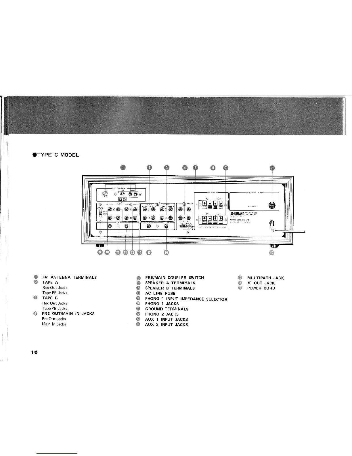
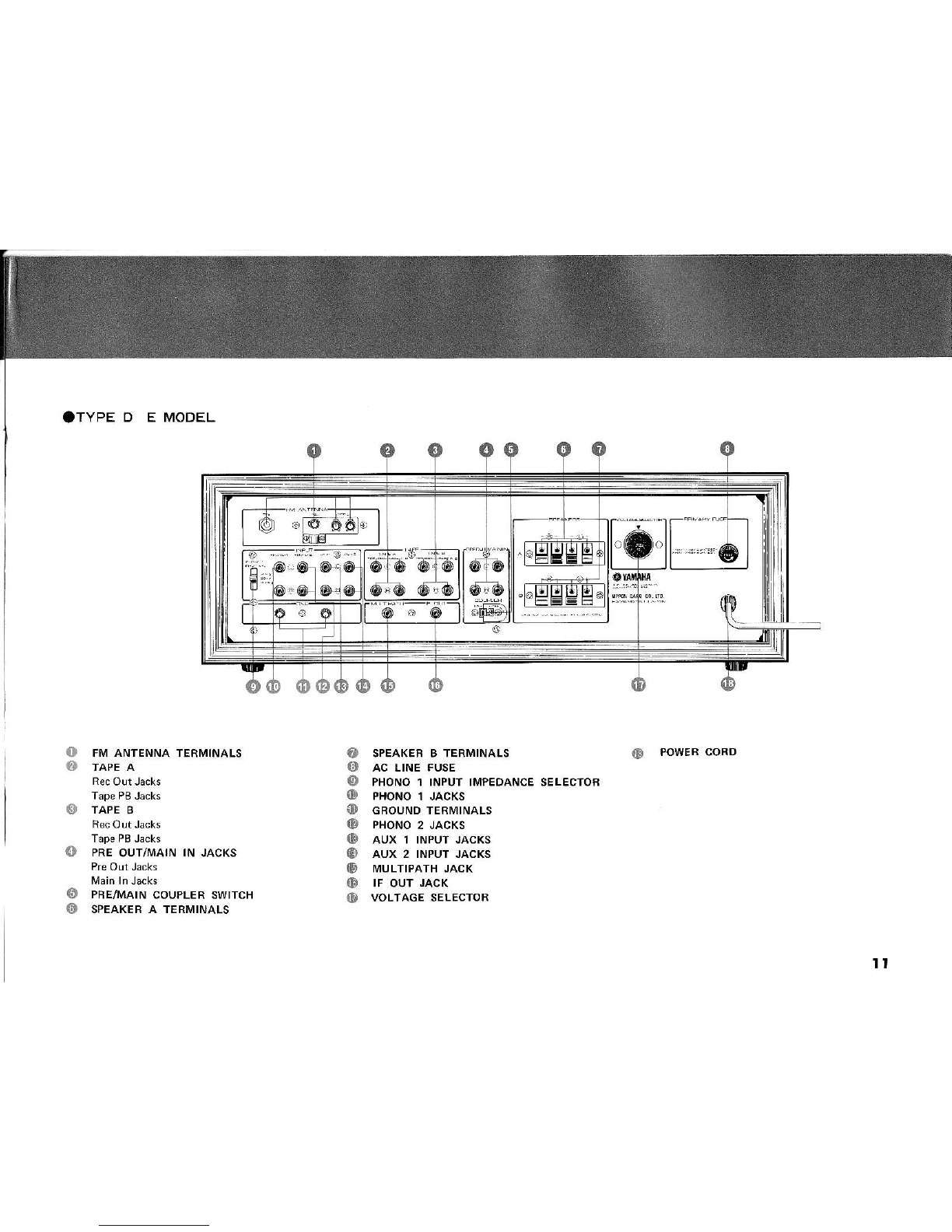
Yamaha CR-1000 User manual

FM BTEFTEG! FIECEIVEFI
cFl-tooo

3

. READ THIS FIRST
You may seriouslydamage
any transistorized
audio
unit by b€inq carelesswhen you first operate it.
carelessnessis
themajorcause
of audiorepairs.Avoid
disappointm€nt
by tollowingthe precautions
listed
belowBEFORE
attempting10 plug in or operate
your cR-1000.
locate
your
unit indirectsunlight
or near
a
sour@
of heat.Heatcandamagetransiston.
iorcethe knobs
or switches.
plug the CR1000 into a wall AC outtet
unless
you aresurethe power
switch isoff.
connect any other equipment hpeakero,
turntables,tape recordersr
erc.) unless
the
Don't turn on the powerswitchuntil you aresure
thatthe speakers
are
properly
connecteo
ans
the volume
is turned
down to minitr,utr,.
Don't plug
a
microphone
into
the"PHONES,
jack.
Do make sure
that air cancirculare
freety above,
under,
andbehind
your unit.
Do protect the cabinet finish from insecticides,
paint thinner and other volatile materiats.
Do protect
your CR-I000from dampnels,
dustand
mechanicalshocks.
Do useonly I ohm speakersif you intend
to play
"A" and "8" speaker
pairs simultaneously.
lf your set has a voltase selector, before you
plug in the power cord check that rhe setector
is set to your local curent.
lf not properly set, turn the knob and reret it to
the coiiect position.
Voltage settings: 11O, 13O, 22O, 240V (the 150,
260V settings
are not connected).
Don't
Don't
Don't
Don't
1

Flrst, connecta stereo
pairof speakers
to the upper
{Alrow
offour
o!tput (SPEAKERS)
terminalson
the
rear
panel
of your
cB-1000.connectthe
(L)
outputs
to your left speaker,and the (R) outputsto your
To a$ure
"in phase'
operationof thetwo speakers,
connecto.ly bLack
( ) output terminalsto (-)
speakerterminals,andred
(+)
outputtermnalsto
(+)
speakertermlnals.SeeFi9.1.
Next, connectthe Fl\4
ribbond;poleantenna
(in-
cludedaccessory)to the two "300" terminah
onthe
rear panelunder "F[4 ANTENNA". See Fig. 2.
Next,makesuretheCB 1000POWERswitchisoff.
Plug the AC power cord into your AC wall ot'tlet.
SET FBONT PANEL CONTBOLSAS FOLLOWS
Now, setthe POWEBL€ver
up to turn theAC power
on.Tune
acro$
the
d
ialforthestronsestFMsignalas
indicated
bymaximum
deflection
(to
therlght)
ofthe
SIGNALmeter.
Finetuneby centeringtheTUNING
meter
indicator.seeFis.3. Thenturn upthevollme,
andcafefully
experimentw th theotherfront panel
Fig.
1
Fis.2
5
AS FOLLOWS
@
Fi9.

@
o
@
@
o
@
o
o
MIC VOLUIVIE
Controlsthe input volume
from a microphone
connected
to the lvlicJack.
Turn off whennot
FM MUTING
Without muting,hissingnoise
will normatty
be
heardwhen
tuningbetween
strongFlrlchannets,
andin lhe background
with very
weakchannek.
ll,4uting
circuitrv blocks that noise {and atso
blocks
weakFA4channels)
by cutting
amptitica-
tion of F14
whenever
incomingsignal
strengthis
below
an established
mutingthreshould.
The
Muting
contro adjusts
thatthreshotd.
SIGNAL & TUNING METERS
SeparateSigna strength
andcenter
of-channel
T!nan9 mete6 enable precise
tuning for
mnimumTVl
d,(.odion
d.d ma\imum
ltereu
LOW FILTER
ShdrolyrpdJcesrumbre
dnd low frequeicy
response
at 12dB per octavebelow s€lectabte
cutoff frequency
of 70H2
or 20H2.
HIGH FILTER
Sharply reduces hiss and high frequency
response
at 6dB per octave above selectable
cutorr frequencyof 6kHz or 12kH2.
DIAL SCALE
Indicaies
thebroadcastfrequ€ncy
of thestation
TURNOVER
{TREBLE)
Seectable frequency range of Trebe tone
control can be abov€2.5kHz,or above5kH.
SelectDefeatfor flat trebe r€sponseregard-
lessof Treble and High Filter settings.
TUBNOVER{BASS)
Selectablefrequency
rangeofBASS
tonecontrol
can be below 500H2 or below 250H2.Select
Defeat for {lat bass f€sponseregardlessof
BassandLowFiltersettings.
5

o
@
o
(D
@
{E
DIAL INDICATOR
TREBLETONE CONTROL
Center
(0)posltion
isfor "flat". Slidershtfor
boost
(+),or left for dimlnish
(-).
BASSTONE CONTBOL
Center
(0) positionisfor "flaf'. Slide
rishtfor
boost,or left for dlminlsh.
BALANCECONTNOL
Center
(0) position
isfor equa amplification
throughboth
channels-
Slide
righttoemphasize
theright
channel
(by
reducingrelativeamplifica
tionoftheleft).
Slide
leftto emphasizethe
left.
LOUDNESS
CONTROL
Slide
leftto decrease
audible
loudneswithout
the usual
apparent
los of b3$ and treble.
AFC/STATION
INDICATORLIGHT
"On" indicatesAFCisoperating.
"Off" indicates
AFC is
defeated.
AFc is
automaticallvdefeated
as
you
touchthetuningknob,to ins!rethat
you
tune precisely
to centeFof-channel.AFC is
automatically restoredwhen you releasethe
FIVISTEREOINDICATOB LIGHT
"On" indicatesreceptionof a stereotransmis
sion.
"Off" indicatesmono.
POWEFINDICATOBLIGHT
TUNING KNOB
POWERSWITCH
(D HEADPHoNE JACK
For standard
8 ohm {or higherimpedance)
dynamicstereoheadphoneswithbinaural
phone
prus.
@ {D SPEAKERSWITCHES
Playeitheror both ("A" and/or
"B") speaker
pairs.
Turn both off for phonesonly.
@ tMrcRoPHoNEJAGK
For onehighimpedancedynamicmi€rophone
with standardmono
phoneplug.
@ MoDE swtrcHEs
lMonoL: A$ignsL channei
inpLrton
y
to both L and R outputs.
F: AssiqnsR channelinputonly
to both L and B outputs.
L+B: CombinesLandRinputs,and
assignsthe resultto L and B
outputs,
Stereo
Normal: AssignsL inputto L output,
and R input to R output.
Stereo
Beve6e: Assiqns
L input to R output,
and R input to L output.
Do nor pross
moretha. two of the rollowing
swkches
ai thesametime:
F!ncrlo.,
Mode,Tap€
@r TAPE SWTTCHES
With two professional
type 3head tape decks
connected,
you canrecordon eitheror both,or
fromone
totheother,withmonitoring.
SWITCHES
To play
atapedeck,tuner,
or
other st€reoprogramsource
connected
to the rear panel
Aux (l or2)
jacks.
To play a turntablewith
magn€tic
stereocaftridgecon
nected to the rear panel
Phono
(1
or
2)
iacks.
@ FUNcrroN
Aux1&2:
Phono
1& 2:
@F[4: TopayFN4.
VOLUME CONTROL
Iti
(s
ffJ
@
7

BesuretoturnofftheCR-1000beforeconnectingordisconnec1inqany
leads.[4ake
allconnectionsfirmandtisht.
OTYPE A IVODEL
*YrnaHA$:li:
!! . Lrg
@
o
o
o
o
FNIANTENNA TEBMINALS
TAPE A
TAPE B
PRE OUT/I/IAIN IN JACKS
PRE/IVIAINCOUPLERSWITCH
SPEAKERA TERMINALS
SPEAKERB TERMINALS
AC OUTLETS-SWITCHED
You can plug your tape recorderor turntable
AC power cord into theseoutlets-With your
CR-1000
powerswitchOn theseoutets are
"llve."With your CR'l000 power
switch
Off,
theseoutletsare
"dead-"
YourCR-1000
power
witch can thus function asa systemOn.Off
AC OUTLETS-UNSWITCHED
Always
powered
whenthe CR'1000power
cord
is plugged
in, regardlessof powerswitchposi
AC LINE FUSE
@ PHoNo 1 TNPUTITTPEDANCE
lD PHoNo 1 JAcKs
IE GROUNDTERMINALs
(D PHoNE2 JAcKs
IE AUX 1 INPUT
JACKS
lD aux 2 |NPUT
JAcKs
ID MULTIPATHJACK
(E rF
our JACK
lD PowEBcoBD
SELECTOB
o
@
oo
a

OTYPE B MODEL
o
@
o
o
o
FM ANTENNA TEBMINALS
TAPE A
TAPE B
PRE
OUT/MAIN IN JACKS
PBE/MAINCOUPLER
SWITCH
SPEAKEF
A TERMINALS
SPEAKER
B TERIVIINALS
AC OUTLETS.SWITCHED
You can plug youf tape r€corderor turntable
AC power cord into theseoutlets.With yolr
CR.l000 power switchOn theseoutletsare
''live."
With your CR.1000
power
swltch
Off,
theseoutletsare"dead.'YourCR 1000
power
switch can thls flnction asa systemOn'Off
AC OI.JTLETS.UNSWITCHED
Always powered when the CR-I000 power
cord is plugged
in, regardlessof power
switch
AC LINE FUSE
IE PHONO1 INPUT
IIIIPEOANCE
{D PHONO1 JACKS
@ cRouND
TERMtNALS
G} PHONO2 JACKS
|!I AUX T INPUTJACKS
ID AUX 2 INPUT
JAcKs
ID MULTIPATHJACK
IE IF oUT JACK
ID VOLTAGESELECTOR
ct PowER coBD
oSELECTOR
@
o
o
9

OTYPE C MODEL
ID
{D
tb
o
o
o
FM ANTENNA TERMINALS
TAPE B
PBE OUT/MAIN IN JACKS
@ PRE/tVtAtN
COUPLEBSWTTCH
(' SPEAKERA TEBMINALS
e) SPEAKEBB TERMTNALS
O Ac LINE
FUSE
O PHoNo
I tNpuT
tMpEDANcE
sELEcroB
IE PHONO
1 JAcKs
O cBouND TERMTNALS
iE PHONo2 JAcKs
lD AUX r |NPUT
JAcKs
IE AUX2 INPUTJAcKs
MULTIPATHJACK
IF OUTJACK
POWEBCOBD
o
lo

OTYPE D E MODEL
o
a
o
o
FM ANTENNA TERIlIINALS
TAPE A
TAPE B
PRE OUT/MAIN IN JACKS
PBE,4\4AIN
COUPLER SWITCH
SPEAKEBA TERMINALS
O SPEAKERB TERMINALS
O Ac L|NEFUSE
O PHoNo1 |NPUT|MPEDANCEsELEcroR
0l pxot'to
t .tlcxs
fl) cBouNDTERMTNALS
@ PHoNo2 JAcKs
lE AUX 1 |NPUTJAcKs
lD AUX2 |NPUTJAcKs
(E MULTIPATHJAGK
ID IFoUT
JACK
I'I VOLTAGE SELECTOR
@ POWEBCORO
o
o
It

I
I
I
I
\
12

ilttT-l
d:v | |
Fi9.4
The Speaker
terminalson the rear
panelpermitcon'
nection of two setsof stereospeakers.
Note: lf you are
contemplating
playing
both setsof
speakereatonce
(A+B
setting),besurethatall
your
speakersare8ohm
impedance
(or
hisher).
Connection
Procedure
1. Connect
the €mplifier
outputsto the speaker
inputs,observing
(+) and {-) polarity as pre
viouslydescribed.lf aspeaker
is
connected
with
amplifier
output {+}to speaker
(-), andoutpLrt
(-) to speaker
(+),
thenthatspeakerissardto
be connectedwith reverse
polarity. With one
speaker
(of a stereo
pair)connected
"normal"
and the other '?eversed",
thosetwo speakers
will play"out of phase",
with apparent
lossof
2. Thesespeakerterminalsaresprlngtypes.As
shownin Fig.4, push
the leverin, insertthe
tlvistedbarewire endof th€ speaker
leadInto
the hole,then releasethe lever.The spring
forcewillholdthewire.
3. lf two paire
of speakersareto beused,
connect
thesecond
p€ir
totheBterminals.
llakesureallspeakerconnectionsare
firmand
SeeFig. 5. With speakerswitchesA and B off, you
can listen to phonesonly. The cable side of the
headphon€
isthe left channelside.
ffir
t]L
t3

Flvt3000:
FII75Q:
ln a strongsignalarea,uselhe indoorT-
shapedribbon antenna. The top of the
"I" shouldbehorizontal
(see
Fis.6). To
determine the best antenna location,
tune in a stronqFtMstationandvarythe
direction in which the antenna
points.
whlte
youwatchthetuningmeter.lvaxi-
mumdeflection
(tothe
right)of
the
meter
will indicateoptimum orientationof the
antenna
for that FI\4
station,
lfyoucan-
not achieveadequatedeflectionwith the
ribbon
antenna,ask
your
dealer
aboutan
outdoor FI\4antenna.
lf you use
an outdoor antenna,connect
it by coaxialcableto theseterminals.
Strlpenough
insulationfromthecoaxial
cableso
you canfastenthe innerconduc
ter
tothebinding
post,
andsothemetallic
outefcable
shieldmakescontactunder
the
clamp
{see
Fls.7i.
Note: lf you mlrstuseregularTV ribbon
lead from the outdoor antenna,
connect to the "300" terminak-
Press
the Fll,,l
switchandtrne to the desiredstation.
First tune for maximum
deflectionof the Signal
meter. Then centerthe Tuning meter. FNIl\,4uting
will cut out unpleasanthissbetweenFN4srations
while
tuninq. On the CRl000 thisisnot a simpe
switch,but a continuouscontrol. In a strongsignal
area you can slide the lever farther to the right
fo. more etfrcie
rt 106e reducr'or
while tunrT.
(see
Fig. 8). In a weak signalarea,
strongmlting
mayako cut somestations;in this
casethemuting
levershould not be set so far to the right.
.-=---+-
t@ 6)el
Er@,',.
-
@
Fig-
7
,,fTfl"
FM MUTING
/ .lIt'
Fig.8
11

l
!
I
:,r
When a stereo broadcastis received,
the stefeo
indicalorlamp ightsup and the setautomatically
tunctionsinstereo.SeeFig-9. lf thelampillckers
or goes
out altog€ther,it indicatesthat the signalis
too weak for sufficlent stereochanne separation.
Locatean outdoor antenna
asf:r aspossibLe
ffom
roads
ormachinery.Larqebuildingsormetalcontaln-
ing struct!reswhich obstructthe signal
path
will
weakenthe signaland causedistortion,
Locatethe antennaashgh as possible. Keep
con
nector leadsas shon as posible and avoidlong
horizonraisections.
T\,!o separatesetsol Phonoinplts permit the con
nection of two magneticcartridge
type turntabler.
With the rear panelswitch,the Phono I input
impeda.cecanbematchedto a
30k!),50k{]or 100
kQ movlngm:gnei (l\,lM),
induced
magnet
(l[4) or
movlng iron (1,41)
cartridSe.
Plus
the phono eacl
pin piugs
lnto the Phono
1 or Phono2 jacks,
and
be sureto connectthe turntable
ground eadto the
CF.1000GndtermnalGee
Fis.10).
Note: WhenusingthePhono1
jacks.
besureto fead
your turntableinstructionmanualcar€fLrlly
andto settheCR1000f€ar
panel
impedance
switch accordinglv.
The switch is factory{et
to 50kQ.
To useth€ Phono 2 jacks,
fint removethe
factoryinstalled shorting plugs from these
Fig.9
FUNl]T]ON -
Errl lErl
Llu
Fig.
10
"g:."@o@
@'',@
" @e@ @"@
t5

PLAYBACK
To listen
todeck"A", pres
A Play.
To listento deck
"B ',press
B Play.
Theseterminalsoffer 150mV input sensitivitv
and
4OkS)imped.nce.To them.connectanothertuner,
stereotapecartridge
player,
TV audiosisna
,etc.;or,
usetheseterrninalsfor connectingturntableswith
high
output
crystalorceramiccaftridges.SeeFig.11.
Wh€nconnecting
a monophonicsourcedevice,con
nectonlyto theL input
jack.
To play,
thendepress
the vlono L l\40de
switch, and that mono source
will be heard throush both L and B speake6.
The CR-1000
{eaturestwo independent
RecOutand
Tape
PB
circults.sothat two stereo
tapedeckscanbe
used. This permitsrecordingfrom Fu.ction (Aux,
Phono,
FM) on both deckssimultaneo!'sly,or dub-
bing from either deck to the other.
. CONNECTION
Connedthe"A" deckLin€ln JacksandtheCR
1000Tape A RecOlt Jacksjconnectthe deck's
LineOut iacks
to the TapeA TapePB
jacks.
Be
sureto connectLsto Ls
andRsro Rs.
Similarly
conneclthe "B' deckto the TapeB
jacks.
SeeFis. 12.
. RECORDING
To record from Function, pr€ssSource. You
cannow recordon deck"A", ondeck"8", or on
boths
mlltaneously.lf deck"A ' lsa3-headtype
(with separaterecord/playback
electronicd,you
can monitordeck
"A" while
recordingby pres
sinqA Pay. Slmilar
y. you canmonitorsucha
3-headdeck"B" by pressing
BPlav.
EtlMI]
6: {3
3IRACK CARIRDGEPLAYER
Fig.1l Cis.12
t6

. DUBBING
To dub from deck A to deck B, set deck A for
playback,and B for recording.Then press
the
A > B Dubbingswitch
(Fig.
13).
To dub from B to A, setd€ckA for recording,B
for playback,
andpress
the B > A Dubbing
swrtch
(Fis.
l4).
Note: Durinsdubbing,the signalcannotbesent
directlythroughtheamplifier.
lf therecord
ingdpck
'( d3.heddtvpe
w lhTonitoring,
thenthesignalcanbemonitored
fromthe
recording
deck.
Never have both dubblng switches
down
atthe sametrme,
Plugthe ricrophone
into
the
r,4ic
iack
Gee
Fig.l5)
and then control its volumewith the l\lic Volume
control. lf "howling" feedbackoccun, move the
mike away from the speakers,or lower the l\,lic
volume. Be sureto slide l\Iic Volumeto Off when
a mic is not being used.
Note: Al,pr rhe N4icVoume coilrol, rhe mic
signal
bypasesall clrclits until the PfeOut
jacks. You canadjustallotherpanel
controls
without affectingthe mic signal,andthe mic
signalwi!l not arive atthetape
playback
out
puts.Torecordmic-plusprogram,connectthe
CR-1000 rear panel Pre Out to your tape
deck's npur. You cdn lh€n m \ rhe mic
andprogram
signak
as
desked
whilerecording.
. SERVICEPADS
These
protectivepads
will adhereto the feetof
your
CR'1000,if
You
first
peeloff
thecover
papers.
+ ii,)/'
- u"k
td
Fig.16
Dubblng (naking a taPe
copy) lrom t6pedeck "A"
Fis.13
Dubbngfrom OeckBto
Fig.
14 Fis.15
t7

Usetonecontrolsto tailorthe soundto your listening
room,ortoYour
mood.
{See
Fis.17).
Ea.h tone control has elevenclick{top positions.
[4ovinsone position changes
the responseby 3dB
{bass)
or 2dB (treble}.
The '0" positionprovides
Setting the turnoler switchesto Defeat wlll also
provide "f at" response.
The Turnover switchesalso control the frequency
ranges
on which the ton€ controlsoperat€.
whh Ba$
Turnover switch set to 500H2, the B:ss tone
controlsoperateon frequencies
below 500H2.With
BassTlrnoler setto 25OHz,the Basstonecontrol
operates
onlyonfrequenciesbelow
250H2.
Similarly,
the Treble Tlrnover switch selectsthe frequency
(5kHz,2.5kHz)
abovewhlch the Treble
tone control
The High Filter sharplycuts all tonesabovethe
selected
frequency. The Low Filter simliarly cuts
low
tones,See
Fig,18.
Use
thelowFilterto attenuate
turntablerumble,etc.,and/orthehighfilter to reduce
record"scratch", tape "hiss", or radio'3tatic". For
maximumfrequencyresponse,settheseswitchesoff.
lf your speakers
arenot ideallypositjoned
in your
room, experiment
with the Balanceleverto balance
the apparentsoundlevelfrom both speakersto your
listening
area.SeeFig.19.
ta
Fis.1a
BALANCE
Fig.19
TREEILE
- _------
:t]]|.---: r""""""" f---------'---l
TURNOVEF BASS

)
l
At low volumelistening
levels,humanhearingis
reativelyinsensitiveto extremebassandtrebletones.
With this control, you can compensate
for that
normalhearing
"def
iciencY".
Flrst, set th€ Loudness
leverto Flat for flat res-
ponse. Then play a program
and set the Volume
controlat the loudestsetting
you normaliyexpectto
use. Now, if you slidethe Loudness
lever
to theleft,
you will redlce the volumewhile at the same
time
inc.easingtheLoudnesscompensatlon.
Fromnowon
you cancontrol the volumewith the Loudness
lever.
SeeFis.20.
With the rear panel Coupler switch On, the CR_
1000stereo
preamp
andpower
amplifiersections
are
internally coupledfor normaloperation. With the
Coupler switch Off, these two sections can be
used
asthoughtheywereseparate
aldro components.
SeeFis.
21.
connectthe oscilloscopeasshown
in Fig.22 in order
to find the ben installation
position. The antenna
shouldbeadjustedso
thatthe oscilloscopewavetorm
isa straight
lineasshownin thefigure. For receivinq
4'channelFlVlbroadcasts
vou can connecta stereo
adaptorto the lF Out terminals.
LOUDNESS
VOLLJME
Fr:J
::ttI
osctLLoscoPE
MULTIPATH
- IF
Fis.22
@
Fig.21
l9

lf theCR-1O00
doesnotseemto functionproperly,
checkthefollowingchartfor suggestions.ll youcannotsolve
theproblem,
contact
yourdealer.
Ndpower
whentheswir.hrurnedon. Pluq not f rmly insehed.
Speakersw ich set to oft
Tape witch h notsetto source.
lmproper tun.lion swtch setting.
Volume turned too low,
Replacewnh tLs or conlacr serv'Gman
Poweri! on,but nosound.
No sound from one channel.
lMSrpreordc"ro. ld"Se5dL nqFM:k,eo'pcep'io4.
No sedurinq FM stereo
reception.
Straiqe h $inq or beepingdur ng FM reception.
F!m during reord play.
Sounddistortiondur ngrecord
play.
lmproperspeakercon.ection,
Oefective
lnpur
jack
onnecrion.
lmpfoperleitiight balan@setting.
Serro properprogram
solrce.
Sei balancecontrol to O '
set modeswrch ro L + R.
Check antenna connectlons.
flepace ribbon anrenna w rh more sp{ a outdoor lype.
Playbackfrom monotaperecorder.
lmproperantennaor weaksignal.
A cl€ar FM ste.eo signalcan be reeive.l onlv to with n a
d $ance aboul halfihatlor an FM mono signal Insa Imore
powertul
ante.na.
Interfe.encefrom alro or mo Makesureto connedantenna
with a rca:ial
I Movg
thelnrennarrthef rromthe*reet
Repositionihe unhson sold bases.
Repacewirh onethai matchesrhecartrldqe.
Separare
p ayerand
speakeGas
Jar
as
posible.
Putasofi,vibraiondamping
materialunderrhe
paver'
Donor
p
a p
ihp'pFdl
e'kl dnd
plavPr
o t rh4
<are
"helr'
P
avef
q.ound
wiredisconnected.
lmproper
position
ng
of pL6yer
and/oramp,
rmproper
pnono
connecrons.
Speakerstoo clde to p ayer
20
Howling during re@rd play when volume rurn€d high.

!l rlrroerorue
8iia
5-
2EAA (
2l
Table of contents
Other Yamaha Stereo Receiver manuals

Yamaha
Yamaha CR-240 User manual

Yamaha
Yamaha RX-V10 User manual

Yamaha
Yamaha RX-700U User manual

Yamaha
Yamaha RX-V590 - AV Receiver - Dark User manual

Yamaha
Yamaha RX-497 User manual

Yamaha
Yamaha CR-640 User manual

Yamaha
Yamaha RX-V470 User manual

Yamaha
Yamaha R-50 User manual

Yamaha
Yamaha RX-V390RDS User manual

Yamaha
Yamaha RX-V660 User manual

Yamaha
Yamaha RX-530 User manual

Yamaha
Yamaha RX-685 User manual

Yamaha
Yamaha RX-550 User manual

Yamaha
Yamaha RX-V670 User manual

Yamaha
Yamaha RX-S602 User manual

Yamaha
Yamaha R-302 User manual

Yamaha
Yamaha RX-V901 User manual

Yamaha
Yamaha HTR-5071 User manual

Yamaha
Yamaha R-9 User manual

Yamaha
Yamaha YHT-3072 User manual