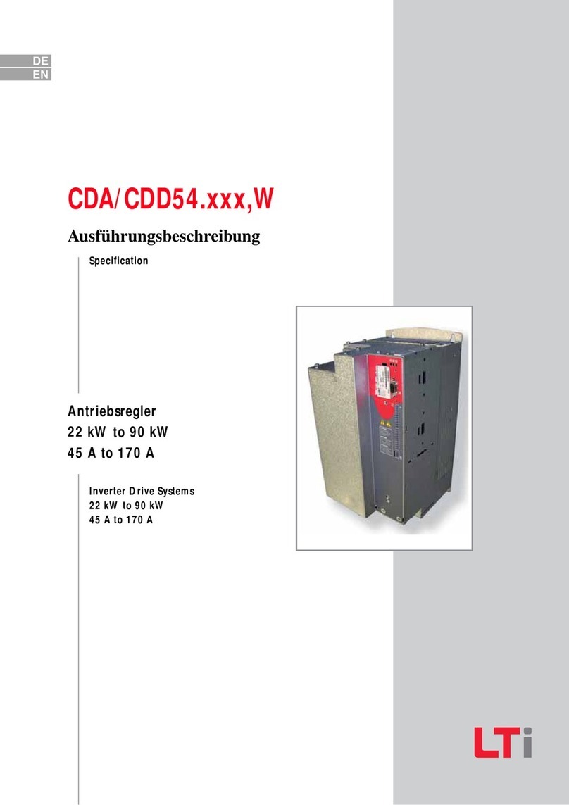
Lust CDA3000 Instructions for use

F1
CDA3000
Adaptation of the drive system
to the application
EN
EN
FR
ES
Application Manual
Inverter drive system
to 90 kW

Overview of documentation
Application Manual CDA3000
ID no.: 0840.22B.0-00
Date: January 2000
We reserve the right to make technical changes.
Before purchase
With shipment
(depending on supply
pakkage)
F1
CDA3000 Catalogue
Selecting and ordering a
drive system
CDA3000 Operation
Manual
Operating Instructions
KEYPAD KP200 Application Manual
Quick and easy initial
commissioning
Operation via
KEYPAD KP200
Adaptation of the drive
system to the application
CANLust Communication
Module Manual
CANopen Communication
Module Manual
PROFIBUS-DP Communi-
cation Module Manual
Project planning,
installation and
commissioning of the
CDA3000 on the field bus
Project planning,
installation and
commissioning of the
CDA3000 on the field bus
Project planning,
installation and
commissioning of the
CDA3000 on the field bus
D
E
F1
G1
G2
G3

Application Manual CDA3000
DE
EN
FR
Dear User,
This manual is aimed primarily at you as a programmer of drive and
automation solutions. It describes how you can adapt your new CDA3000
drive system optimally to your specific application. We assume that your
drive is already running – if not, you should first consult the Operation
Manual.
Don't be put off by the size of the manual: Only sections 1 to 3 contain
essential information with which you need to familiarize yourself. The
remaining sections and the appendix are provided as reference
resources: They demonstrate the full scope of functions and flexibility of
the CDA3000's software package in solving a wide variety of drive tasks.
In those sections you can concentrate on the functions relevant to your
own application, such as power failure bridging or DC braking.
Good luck, and have a nice day!
How to use
this manual
1 Safety
2 Inverter module CDA3000
Appendix: Parameter overview, Error table, Glossary
Index
A
3 User interface and data structure
5 Functions and parameters
6 Control modes
1
2
3
4 Preset solutions 4
5
6

Pictograms
➢ Attention! Misoperation may result in damage to the
drive or malfunctions.
➢ Danger from electrical tension! Improper behaviour
may endanger human life.
➢ Danger from rotating parts! The drive may start run-
ning automatically.
➢ Note: Useful information.

Application Manual CDA3000
DE
EN
FR
Table of contents
1Safety
1.1 Measures for your safety ........................................1-1
1.2 Intended use ...........................................................1-2
1.3 Responsibility .........................................................1-2
2 Inverter module CDA3000
2.1 Device and terminal view .......................................2-2
2.2 Module mounting ....................................................2-4
2.3 Ambient conditions .................................................2-5
2.4 Specification of control terminals ..........................2-6
2.5 LEDs .......................................................................2-11
2.6 Isolation concept ...................................................2-12
2.7 Reset ......................................................................2-14
2.8 Loading device software .......................................2-16
3 User interface and data structure
3.1 Data structure .........................................................3-2
3.1.1 Application data sets ............................................3-4
3.1.2 User data sets ......................................................3-5
3.1.3 Characteristic data sets .......................................3-6
3.2 User levels in the parameter structure ..................3-7
3.3 Operation with KEYPAD KP200 .................................3-9
3.4 Operation with DRIVEMANAGER ..............................3-12
3.5 Commissioning ......................................................3-13
4 Preset solutions
4.1 Activating a preset ..................................................4-2
4.2 Selection of preset ..................................................4-3

Application Manual CDA3000
4.3 Traction and lifting drive ....................................... 4-7
4.3.1 DRV_1 ................................................................. 4-9
4.3.2 DRV_2 ............................................................... 4-11
4.3.3 DRV_3 ............................................................... 4-14
4.3.4 DRV_4 ............................................................... 4-17
4.3.5 DRV_5 ............................................................... 4-20
4.3.6 Comparison of parameters, traction and lifting drive .
4-23
4.4 Rotational drive ..................................................... 4-26
4.4.1 ROT_1 ............................................................... 4-28
4.4.2 ROT_2 ............................................................... 4-30
4.4.3 ROT_3 ............................................................... 4-32
4.4.4 Comparison of parameters, rotational drives ...... 4-35
4.5 Field bus operation ...............................................4-37
4.5.1 BUS_1 ............................................................... 4-39
4.5.2 BUS_2 ............................................................... 4-40
4.5.3 BUS_3 ............................................................... 4-42
4.5.4 Comparison of parameters, field bus operation ..4-44
4.6 Master/Slave operation ........................................ 4-46
4.6.1 M-S_1 ............................................................... 4-50
4.6.2 M-S_2 ............................................................... 4-52
4.6.3 M-S_3 ............................................................... 4-54
4.6.4 M-S_4 ............................................................... 4-56
4.6.5 Comparison of parameters,
Master/Slave operation ...................................... 4-58
5 Software functions
5.1 _15FC-First commissioning ................................... 5-4
5.2 Inputs and outputs ................................................5-10
5.2.1 _18IA-Analog inputs .......................................... 5-10
5.2.2 _200A-Analog output ........................................ 5-14
5.2.3 _21ID-Digital inputs ......................................... 5-17
5.2.4 _24OD-Digital outputs ....................................... 5-21
5.2.5 _25CK-Clock input/Clock output ........................ 5-24
5.2.6 _28RS-Reference structure ............................... 5-26
5.2.7 _26CL-Control location ...................................... 5-34
Application Manual CDA3000
DE
EN
FR
5.3 Protection and information ...................................5-37
5.3.1 _30OL-Frequency limitation ...............................5-37
5.3.2 _33MO-Motor protection ...................................5-39
5.3.3 Device protection ...............................................5-45
5.3.4 _34PF-Power failure bridging ............................5-47
5.3.5 _36KP-KEYPAD ...................................................5-51
5.3.6 _38TX-Device capacity utilization ......................5-53
5.3.7 _39DD-Device data ...........................................5-55
5.3.8 _VAL-Actual values ............................................5-56
5.3.9 _50WA-Warning messages ................................5-59
5.3.10 _51ER-Error messages ......................................5-62
5.4 Bus operation and option modules ......................5-65
5.4.1 _55LB-LUSTBUS ..................................................5-65
5.4.2 _57OP-Option modules ......................................5-67
5.5 Open-loop and closed-loop control ......................5-69
5.5.1 _31MB-Motor holding brake ..............................5-69
5.5.2 _32MP-MOP function ........................................5-71
5.5.3 _59DP-Driving profile generator .........................5-74
5.5.4 _27FF-Fixed frequencies ...................................5-78
5.5.5 _60TB-Driving sets ............................................5-79
5.5.6 _65CS-Characteristic data set (CDS) ..................5-82
5.5.7 _66MS-Master/Slave operation ..........................5-84
5.5.8 _67BR-DC braking .............................................5-87
5.5.9 _68HO-DC holding-on ........................................5-90
5.5.10 _80CC-Current controller ...................................5-91
5.5.11 _64CA-Current-controlled startup ......................5-93
5.5.12 _69PM-Modulation ............................................5-98
5.5.13 _84MD-Motor data ..........................................5-101
6 Control modes
6.1 Voltage Frequency Control (VFC) ............................6-4
6.1.1 _70VF-Voltage Frequency Control ........................6-7
6.1.2 _74IR-IxR load compensation ............................6-12
6.1.3 _75SL-Slip compensation ..................................6-14
6.1.4 _76CI-Current injection ......................................6-16
6.1.5 _77MP-Magnetization ........................................6-18

Application Manual CDA3000
6.2 Sensorless Flux Control (SFC) ..............................6-20
6.2.1 _78SS-Speed controller SFC ............................. 6-25
6.2.2 _80CC-Current controller .................................. 6-27
6.2.3 Tips and optimization aids for control engineers 6-28
6.3 Field-Oriented Regulation (FOR) ..........................6-38
6.3.1 _79EN-Encoder evaluation ................................ 6-41
6.3.2 _81SC-Speed controller FOR ............................. 6-43
6.3.3 _80CC-Current controller ................................... 6-45
A Overview of parameters
B Error messages
C Index

Application Manual CDA3000 1-1
DE
EN
FR
1
2
3
4
5
6
7
A
1Safety
1.1 Measures for
your safety
The CDA3000 inverter drives are quick and safe to handle. For your own
safety and for the safe functioning of your device, please be sure to
observe the following points:
Read the Operation Manual first!
• Follow the safety instructions!
Electric drives are dangerous:
• Electrical voltages > 230 V/460 V: Dangerously high
voltages may still be present 10 minutes after the power is
cut, so always make sure the system is no longer live!
• Rotating parts
• Hot surfaces
Your qualification:
• In order to prevent personal injury and damage to pro-
perty, only personnel with electrical engineering qualifica-
tions may work on the device.
• The qualified personnel must familiarize themselves with
the Operation Manual (refer to IEC364, DIN VDE0100).
• Knowledge of national accident prevention regulations
(e.g. VBG 4 in Germany, regulations laid down by the
employers' liability insurance associations) is essential.
During installation observe the following instructions:
• Always comply with the connection conditions and
technical specifications.
• Comply with the standards for electrical installations,
such as regarding wire cross-section, grounding lead and
ground connections.
• Do not touch electronic components and contacts
(electrostatic discharge may destroy components).

1-2
1 Safety
1.2 Intended use Inverter drives are components that are intended for installation in electri-
cal systems or machines. The inverter may not be commissioned (i.e. it
may not be put to its intended use) until it has been established that the
machine as a unit complies with the provisions of the EC Machinery
Directive (89/392/EEC). EN 60204 (Safety of machines) must be
observed.
If the frequency inverter is used for special applications (e.g. in areas
subject to explosion hazard), the required standards and regulations
(e.g. EN 50014, “General provisions” and EN 50018 “Flameproof enclo-
sure”) must always be observed.
Repairs may only be carried out by authorized repair workshops.
Unauthorized opening and incorrect intervention could lead to physical
injury or material damage. The warranty provided by LUST would thereby
be rendered void.
1.3 Responsibility Electronic devices are fundamentally not fail-safe. The company setting
up and/or operating the machine or plant is itself responsible for ensuring
that the drive is rendered safe if the device fails.
EN 60204-1/DIN VDE 0113 “Safety of machines”, in the section on “Elec-
trical equipment of machines”, stipulates safety requirements for electrical
controls. The requirements are intended to protect the safety of personnel
and machines and to maintain the function capability of the machine or
plant, and must be observed.
The function of an emergency off system does not necessarily have to cut
the power supply to the drive. To protect against danger, it may be more
beneficial to maintain individual drives in operation or to initiate specific
safety sequences. Execution of the emergency off measure is assessed
by means of a risk analysis of the machine or plant, including the electri-
cal equipment to EN 1050, and is determined with selection of the circuit
category in accordance with prEN 954 “Safety of machines – Safety-rela-
ted parts of controls”.
The CDA3000 conforms to the Low Voltage Directive
(73/23/EEC).
EMC The following generic standards are complied with in applica-
tion of the installation instructions:
• EN 50081-1 and EN 50081-2 (line-borne and radiated
interference emission)
• IEC 1000-4-2 to 5 / EN61000-4-2 to 5 (Interference
immunity of the inverter module)

Application Manual CDA3000 2-1
DE
EN
1
2
3
4
5
6
7
A
2 Inverter module CDA3000
2.1 Device and terminal view .......................................2-2
2.2 Module mounting ....................................................2-4
2.3 Ambient conditions .................................................2-5
2.4 Specification of control terminals ..........................2-6
2.5 LEDs .......................................................................2-11
2.6 Isolation concept ...................................................2-12
2.7 Reset ......................................................................2-14
2.8 Loading device software .......................................2-16
This section sets out basic aspects of the device hardware which are
essential to understanding and using the Application Manual. For more
information on the device hardware refer to the CDA3000 Operation
Manual.

2-2
Application Manual CDA3000
2 Inverter module CDA3000
2.1 Device and
terminal view
Fig. 2.1 Layout, CDA3000
No. Designation Function
H1, H2, H3 LEDs Device status display
X1 Power terminal Mains, motor, braking resistor (L+/RB),
DC supply
X2 Control terminal
4 digital inputs
3 digital outputs (of which 1 relay)
2 analog inputs
1 analog output
X3 PTC terminal PTC, Klixon evaluation or linear temperature
transmitter
Table 2.1 Key to Fig. 2.1
X4
X2
X1
X1
X3
(1)
(2)
X10
X11
X12
CDA34.xxx
CANopen/CANLust
UM-8I4O
CDA32.xxx
L1
U
V
W
L+
RB
L-
L3
L2
L1
U
V
W
L+
RB
L-
N
20
19
18
17
16
15
14
13
12
11
10
9
8
7
6
5
4
3
2
1
1
2
X15
21
22
23
24
25
26
27
28
29
30
31
32
33
34
35
1
2
X10
X11
PROFIBUS-DP
1
2
X13 X13
H1 H2 H3
X7
X6
S1
S2

Application Manual CDA3000 2-3
2 Inverter module CDA3000
DE
EN
1
2
3
4
5
6
7
A
X4 RS232 terminal for DRIVEMANAGER or KEYPAD KP200
X6 Option slot 1 e.g. for user module UM8I4O
X7 Option slot 2 e.g. for communication module
X10 Voltage supply
for communication module + 24 V, ground
X11 CAN-In / PROFIBUS-DP Bus connection input
X12 CAN-Out CAN bus connection output
X13 Address coding plug Only for CANopen, Profibus DP
X15 User module UM-8I4O
Voltage supply,
8 digital inputs,
4 digital outputs
(1) Reset button See section 2.7
(2) Boot button See section 2.7
S1, S2 Address coding switch Only for CANopen, Profibus DP
No. Designation Function
Table 2.1 Key to Fig. 2.1

2-4
Application Manual CDA3000
2 Inverter module CDA3000
2.2 Module
mounting
Inverter modules up to size BG5 are side mounted. To remove them,
press the red release lever on the front and withdraw the module to the
side.
As from size BG6 the modules are built-in. This additionally requires
mounting package MP-xxxx for each module (see Order Catalogue).
The modules are interconnected with the aid of the mounting package
from X6 →X6 and X7 →X7.
Attention: Do not plug modules in during operation.
Inverter module BG1 ... BG5 Inverter module BG6 ... BG8
X6 = option slot 1 for
user modules (UM-xxxx)
X7 = option slot 2 for
communication modules (CM-xxxx).
The CDA3000 inverter modules have two option
slots to accommodate user and communication
modules.
Figure 2.2 Mounting of user/communication modules
X1
L3
U
V
W
RB+
RB
L-
L1
L2
H1 H2 H3
X4
X2
X3
ACHTUNG
Kondensatorent-
ladezeit >3 Min.
Betriebsanleitung
beachten!
WARNING
capacitor disscharge
time >3 minutes.
Pay attention to the
operation manual!
ATTENTION
temps de decharge
du condensteur
>3 min. observer le
mode dèmploi!
!
ANTRIEBSTECHNIK
SN.:
000.000.00000000
Typ:
Netz:
Ausg.:
D-35633Lahnau
12
ANTRIEBSTECHNIK
SN.:
000.000.00000000
Typ:
Netz:
Ausg.:
D-35633Lahnau
1234516 17 18 19 20
11 12 13 14 15
678910
ANTRIEBSTECHNIK
SN.:
000.000.00000000
Typ:
Netz:
Ausg.:
D-35633Lahnau
X6
klick!
X7
L+
L2 RB
L-
L1 L3 UVW
H1 H2 H3
X4
start
enter
stop
return
VAL
Hz
X6
X7

Application Manual CDA3000 2-5
2 Inverter module CDA3000
DE
EN
1
2
3
4
5
6
7
A
2.3 Ambient
conditions
Feature Inverter module User and
communication module
Tempera-
ture range
in operation
-10 ... 45 ° C (BG1 ... BG5)
0 ... 40 ° C (BG6 ... BG8)
with power reduction
to 55 ° C
-10 ... 55 °C
in storage -25 ... +55 °C
in transit -25 ... +70 °C
Relative air humidity 15 ... 85 %, condensation not permitted
Mechanical
strength to
IEC 68-2-6
in stationary
operation
Vibration: 0.075 mm in frequency range 10 ... 58 Hz
Shock: 9.8 m/s2 in frequency range >58 ... 500 Hz
in transit Vibration: 3.5 mm in frequency range 5 ... 9 Hz
Shock: 9.8 m/s2 in frequency range >9 ... 500 Hz
Protection
Device menu IP20 (NEMA 1)
Cooling
method
Cold plate IP20
Push-through heat sink IP54
(3 ...15 kW)
Push-through heat sink IP20
(22 ... 37 kW)
Convection IP20
Touch protection VBG 4
Power reduction See section 5.5.12 “Modula-
tion” None
Mounting
height
Up to 1000 m above MSL, above 1000 m above MSL
with power reduction of 1% per 100 m, max. 2000 m
above MSL
Table 2.2 Ambient conditions of the modules

2-6
Application Manual CDA3000
2 Inverter module CDA3000
2.4 Specification
of control
terminals
Inverter module CDA3000
Des.
Terminal
Specification floating
Analog inputs
ISA00 X2-2 •U
IN = +10 V DC, ±10 V DC
IIN = (0) 4-20 mA DC, software-switchable to:
• 24 V digital input, PLC-compatible (IEC1131)
• Switching level Low/High: <4.8 V / >8 V DC
• Resolution 10-bit
•R
IN=110kΩ
• Sampling cycle 1 ms
• Floating against digital ground
U: ±1% mea-
sured value
I: ±1% mea-
sured value
ISA01 X2-3 • UIN = +10 V DC, software-switchable to:
• 24 V digital input, PLC-compatible (IEC1131)
• Switching level Low/High: <4.8 V / >8 V DC
• Resolution 10-bit
•R
IN=110 kΩ
• Sampling cycle 1 ms
• Floating against digital ground
U: ±1% mea-
sured value
Analog output
OSA00 X2-5 • PWM with carrier frequency 19.8 kHz
•f
Limit = 1.1 kHz
•R
OUT=100 Ω
•U
out=+10 V DC
•I
max=5 mA
• Short-circuit proof
• Internal signal delay ≈1ms
• Tolerance ± 2.5 %
✔
Digital inputs
ISD00 X2-9 • Limit frequency 5 kHz
• PLC-compatible (IEC1131)
• Switching level Low/High: <5 V / >12 V DC
•I
max at 24 V = 10 mA
•R
IN = 3 kW
• Internal signal delay ≈100 µs
• Sampling cycle 1 ms
✔
1) Applicable to limited degree
Table 2.3 Specification of control terminals

Application Manual CDA3000 2-7
2 Inverter module CDA3000
DE
EN
1
2
3
4
5
6
7
A
ISD01 X2-10 • Limit frequency 500 kHz
• PLC-compatible (IEC1131)
• Switching level Low/High: <5 V / >12 V DC
•I
max at 24 V = 10 mA
•R
IN = 3 kW
• Internal signal delay ≈2 µs
• Sampling cycle 1 ms
• Data input with reference coupling (Master/Slave)
✔
ISD02 X2-11 • Limit frequency 500 kHz
• PLC-compatible (IEC1131)
• Switching level Low/High: <5 V / >12 V DC
•I
max at 24 V = 10 mA
•R
IN = 3 kW
• Internal signal delay ≈2 µs
• Sampling cycle 1 ms
• A-input with square encoder evaluation for 24V HTL
encoder against GND_EXT
• Permissible pulse counts 32...16384 pulses per
rev. (2nwith n = 5...14)
✔
ISD03 X2-12 • Limit frequency 500 kHz
• PLC-compatible (IEC1131)
• Switching level Low/High: <5 V / >12 V DC
•I
max at 24 V = 10 mA
•R
IN = 3 kW
• Internal signal delay ≈2 µs
• Sampling cycle 1 ms
• B-input with square encoder evaluation for 24V HTL
encoder against GND_EXT
• Permissible pulse counts 32...16384 pulses per
rev. (2nwith n = 5...14)
✔
ENPO X2-8 • Power stage enable = High level
• Switching level Low/High: <5 V / >12 V DC
•I
max at 24 V = 10 mA
•R
IN = 3 kW
• Internal signal delay ≈20 µs
• Sampling cycle 1 ms
• PLC-compatible (IEC1131)
✔
Des.
Terminal
Specification floating
1) Applicable to limited degree
Table 2.3 Specification of control terminals

2-8
Application Manual CDA3000
2 Inverter module CDA3000
Digital outputs
OSD00 X2-15 • Short-circuit proof
• PLC-compatible (IEC1131)
•I
max = 50 mA
• Internal signal delay ≈250 µs
• Sampling cycle 1 ms
• Protection against inductive load
• High-side driver
✔
OSD01 X2-16 • Short-circuit proof with 24V supply from inverter
module
• PLC-compatible (IEC1131)
•I
max 50mA
• Internal signal delay ≈2 µs
• Sampling cycle 1 ms
• No internal freewheeling diode; provide external
protection
• High-side driver
• Data output with reference coupling
✔1)
Relay output
OSD02 X2-18
X2-19
X2-20
• Relay 48 V / 1 A AC, changeover contact
• Usage category AC1
• Operating delay approx. 10 ms
✔
Motor temperature monitor
PTC1/2 X3-1
X3-2
• Measured voltage max. 12 V DC
• Measuring range 100 Ω- 15 kΩ
• suitable for PTC to DIN 44082
• suitable for temperature sensor KTY84, yellow
• suitable for thermo self switch (Klixon)
• Sampling time 5 ms
✔
Voltage supply
+10.5V X2-1 • Auxiliary voltage UR=10.5 V DC
• Short-circuit proof
•I
max = 5 mA
–
+24V X2-6
X2-7
X2-13
• Auxiliary voltage UV= 24 V DC
• Short-circuit proof
•I
max = 200 mA (overall, also includes the driver
currents for outputs OSDox)
• No polarity reversal protection
✔
Analog ground
AGND X2-4 • Isolated from DGND
Digital ground
Des.
Terminal
Specification floating
1) Applicable to limited degree
Table 2.3 Specification of control terminals

Application Manual CDA3000 2-9
2 Inverter module CDA3000
DE
EN
1
2
3
4
5
6
7
A
Note: The sampling time of the inputs and outputs is 1 ms. The digital
voltages relate to the digital ground and the analog voltages to the
analog ground.
Pinout of the serial interface X4
DGND X2-14
X2-17
•IsolatedfromAGND
Pin No. Function
1+15VDCforK
EYPAD KP200
2 TxD, Transmit data
3RxD,Receivedata
4 NC, free contact
5 GND for +15 V DC of the KEYPAD KP200
6 +24 V DC, supply voltage for control board
7 NC, free contact
8 NC, free contact
9 GND for +24 V SDC, supply voltage for control board
Tabelle 2.4 Spezification of interface pins
Des.
Terminal
Specification floating
1) Applicable to limited degree
Table 2.3 Specification of control terminals

2-10
Application Manual CDA3000
2 Inverter module CDA3000
User module UM-8I4O
Des.
Terminal
Specification floating
Digital input
+24V DC X15-21 Supply voltage for IEDxx
IED00 to
IED07
X15-22
to
X15-29
• Limit frequency 5 kHz
• PLC-compatible (IEC1131)
• Switching level Low/High: >5 V / >15 V DC
•I
max at 24 V = 6 mA
•R
IN = 4 kΩ
• Internal signal delay ≈2 µs
• Sampling cycle 1 ms
✔
DGND X15-30 • Digital ground for IEDxx
OED00
to
OED03
X15-32
to
X15-35
• Short-circuit proof, Ikmax = 1.2 A/OEDxx
• PLC-compatible (IEC1131)
• Current at “1”: Imin = 5 mA
Imax = 500 mA
•I
max in parallel operation = 125 mA
• Internal signal delay ≈250 µs
• Sampling cycle 1 ms
• Protection against inductive load
• Thermal overload protection
• High-side driver
✔
DGND X15-31 • Digital ground for OEDxx
Supply voltage, module feed
+24V DC X15-1 • UV= 24 V DC +20%
• I = 0.6 A
• No protection against false polarity
DGND X15-2 • Digital ground
Table 2.5 Specification of control terminals UM-8I4O
Other manuals for CDA3000
3
Table of contents
Other Lust Inverter Drive manuals