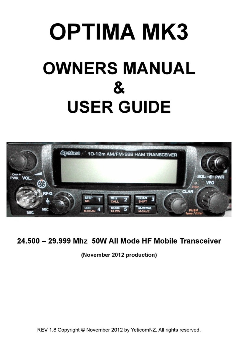
Yeticomnz Optima MK2 Guide

OPTIMA MK2
OWNERS MANUAL
&
USER GUIDE
24.500 – 29.999 Mhz 50W All Mode HF Mob le Transce ver
(February 2012 product on)
REV 1.61 Copyright © January 2012 by YeticomNZ. A rights reserved.

TABLE OF CONTENTS
Introduction ......................................................................................................... 3
Notification of new functiona ity.............................................................................3
Limited Warranty.................................................................................................. 4
Insta ation ...................................................................................................... 5 - 6
Microphone Wiring........................................................................................5, 6, 7
Mode Information (Jumper Settings).................................................................6, 9
Front Pane Contro s .................................................................................... ...7- 9
Step Function........................................................................................................7
Sp it Frequency Operation....................................................................................8
Memory Function..................................................................................................8
Other Features .................................................................................................... 9
Specifications .....................................................................................................10
User Information..................................................................................................11
Contact Information ........................................................................................... 12
2

INTRODUCTION
Congratu ations on your purchase of Yeticom's OPTIMA 10/12 meter SSB/AM/FM transceiver. The OPTIMA
is designed to provide years of enjoyment and troub e-free service. There are many features and functions
designed into this transceiver. To ensure that your investment is enjoyed to its fu est extent, p ease take a
few moments and thorough y read this manua .
The OPTIMA is a 50w a mode microprocessor contro ed, user programmab e radio combining high RF
performance with a user-friend y environment. The OPTIMA is a 12 vo t DC, HF transceiver designed for
mobi e use. The transceiver uti izes the atest in surface mount production techniques. This keeps the size of
the unit to a minimum without sacrificing any of the advanced circuits required for today’s high performance
radios, and as cabin space diminishes in modern vehic es, this concept he ps create a wider variety of
insta ation options. A though engineered with mobi e use in mind the OPTIMA, with the addition of a high
qua ity 10-amp power supp y, may be easi y adapted for fixed station operation.
Some of the features of the OPTIMA are; an advanced design iquid crysta disp ay that provides the operator
with a fu visua account of the transceivers operating status, automatic frequency or memory scanning,
memory storage of your favorite frequencies and modes, programmab e frequency reso ution of either 1 kHz,
5khz, 10 kHz, 100 kHz and 1mhz, and sp it frequency operation for repeater use. The defau t frequency step
is 5khz and the radio inc udes fu coverage the new 12m Amateur band. A sma fan has been added to the
heat sink to ensure coo operation in warmer c imates. A second fi ter has been added to the IF chain and
this can be switched in or out from the front pane as required. The 8 pin microphone p ug is compatib e with
most icom microphones and base microphones can be easi y rewired to suit the OPTIMA. These are just a
few of the features that make the OPTIMA a p easure to own and operate.
IMPORTANT: The OPTIMA is designed for amateur radio use. In many countries a icensed amateur radio
operator must be present at the station. P ease make sure you comp y with the icencing regu ations in p ace
for the country you are operating in.
NOTICE:
The fo owing paragraph out ines the changes made to the radio for the February 2012 production.
1. Step Funct on. The step function defau t is 5khz. The radio wi defau t to 5khz when the radio is
powered on. On previous mode s the radio wou d on y ho d the step function chosen unti another
function was engaged (ie press the PTT) upon which the radio wou d revert to 5khz step function.
From the 2012 MK2 re ease onwards the step function chosen by the step button 1, wi remain unti
either changed by the step function or the radios is powered off, when the step wi revert to 5khz.
The choice of 1khz, 5khz, 10khz, and 100khz is retained.
2. M c Ga n. The mic gain circuits have been increased a further 10db for 2012 to a ow for stronger
FM audio and a ow greater contro of user supp ied microphones. In SSB the best audio with
supp ied microphone wi be about 50% or 12 O'c ock. More may cause overmodu ation and a
decrease in SSB audio qua ity.
3. Funct on Sw tch. The function switch has been removed from the c arifier and is now ocated on
VFO frequency se ector contro . This is to a ow users to activate the function contro without
disturbing the c arifier position.
3
Depress VFO
knob to act vate
FUNCTION

LIMITED WARRANTY
YeticomNZ warrants this product to be free of defects for a period of one (1) year from the origina
date of purchase.
This warranty is non-transferab e. This imited warranty is subject to repair or rep acement
of defective components on y. This warranty is void if the radio has been tampered with or misused.
In the event of a ma function the radio shou d be returned to the factory for examination and repair. This
a ows us to maintain the qua ity of the product and become aquainted with any prob ems occurring in the
fie d and to effect changes in future production if required. Freight to factory wi be paid by owner whi e the
fau t is assesed. Shou d the fau t be deemed to be caused by operator abuse or misuse then the repair and
freight costs wi be charged to the customer. If the fau t is caused by product or component fai ure the cost of
shipping and repair wi be borne by the company within the one year period as stipu ated above.
This factory repair warranty app ies to radios purchased though YeticomNZ but may a so be va id for other
se ers on discussion with the factory. Contact 91dd018@gmai .com re warranty issues.
Spare parts may a so be purchased as required. Additiona microphones, power cords, spare knobs etc.
P ease be carefu of the microphone p ug ayout when configuring user supp ied microphones as there are
ive vo tages supp ied to run e ectret type microphone e ements that shou d not be used on dynamic
microphones. (Pin 2 +8V DC)
The driver and PA fina transistors are IRF 520 MOSFET devices. (3 ea)
Seria Number. The seria number is found on the rear of the radio on the outside of the heatsink connected
to the fan.
IMPORTANT: RETAIN YOUR SALES RECEIPT/PROOF OF PAYMENT
4

INSTALLATION
1. Contents
Unpack and inspect your OPTIMA for missing or
damaged components. Your OPTIMA inc udes the
fo owing items:
Quantity Description
1 YeticomNZ OPTIMA Transceiver
1 Microphone with Up/Down Contro s
1 Mounting Bracket with Hardware
1 Microphone Hanger with Hardware Set
1 Operating Manua and DC power cord
2. M crophone Hanger
The microphone hanger may be attached to the
side of the transceiver, or any other convenient
ocation. Use the provided screws to attach the
microphone hanger either vertica y or horizonta y to
the side of the transceiver.
3. Mount ng
When attaching the OPTIMA mounting bracket to
the vehic e, choose a ocation that wi provide easy
access to a front pane contro s and air circu ation to
the rear pane . When se ecting a mounting ocation,
make sure that there is amp e space behind the contro
deck for the cab es. Do not pinch, or bend sharp y, the
power or antenna cab es. Do not insta the OPTIMA in
any compartment that restricts airf ow and do not insta
in a ocation that interferes with the safe operation of
the vehic e.
Attach the mounting bracket to the vehic e first then
mount the OPTIMA to the bracket. If the rear pane is
not accessib e you may want to attach the power and
antenna cab e prior to mounting.
4. Electr cal Connect ons
The OPTIMA is designed to work on any 13.8 vo t
DC, negative ground, source. The condition of a
vehic e’s e ectrica system can affect operation. A ow
battery, worn generator/a ternator, or poor vo tage
regu ator wi serious y impair the performance of the
transceiver. Any of the above conditions cou d resu t in
a high eve of receiver noise generation or a
substantia oss of the transmitter’s RF output. Make
sure that a of these components of your vehic e’s
e ectrica system are in good condition prior to insta ing
the transceiver.
CAUTION!
VOLTAGE EXCEEDING 15 VDC WILL DAMAGE
THE RADIO. MEASURE VOLTAGE AT BATTERY
TERMINALS, WITH VEHICLE RUNNING, PRIOR
TO INSTALLATION!
Before making any e ectrica connections make sure
the AF gain (vo ume) contro on the contro deck is in
the “OFF” position.
Connect the positive (+) red wire of the DC power cord to a
positive 13.8 vo t source at the vehic e fuse b ock. If
connecting to the fuse b ock, it is recommended that a
switched power source is used so that the power to the
transceiver is disconnected when the vehic e is off. This wi
e iminate the possibi ity of the transceiver draining the
vehic e’s battery.
Fuse 12A s ow b ow type
Connect the negative (-) b ack wire to a meta part of
the vehic e’s frame, or chassis ground. Make sure that
this is a good ground connection.
The OPTIMA power cord may a so be connected direct y to
the battery. Connecting direct y to the battery has severa
benefits, the first of which is to maximize RF output.
Second y, the battery is a very arge capacitor and
wi he p e iminate certain types of ambient and vehic e
noise. If connecting direct y to the vehic e’s battery,
additiona power cab e may be required. On runs of 8
feet or ess use 12-gauge stranded wire. Use 10-gauge
wire on onger runs.
5. Antenna Connect on
The transceiver wi operate using any standard 50-
ohm ground-p ane, vertica , mobi e whip, ong wire or
simi ar antenna. The antenna shou d be rated at 50
watts PEP minimum. A standard SO-239 type antenna
connector is ocated on the rear pane of the OPTIMA.
Connection is made using a PL-259 and high grade coaxia
cab e (RG213, RG58A/U or Mini RG-8 is recommended).
A ground-p ane antenna provides greater coverage and
is recommended for fixed station-to-mobi e operation.
For point-to-point fixed station operation, a directiona
beam antenna operates at greater distances even under
adverse conditions. A non-directiona antenna shou d be
used in a mobi e insta ation; a vertica whip is best suited
for this purpose. The base oaded whip antenna norma y
provides effective communications.
For greater range and more re iab e operation, a fu
quarter wave whip may be used. Either of these antennas
uses the meta vehic e body as a ground p ane.
Once the antenna is mounted on the vehic e, route the
coaxia cab e so that it is not next to any power cab es
or vehic e cab es. Connect the PL-259 to the antenna
connector on the rear pane of the OPTIMA. Make sure that
the cab es does not interfere with the safe operation of
the vehic e.
M crophone Connect ons
Pin 1 Mic Input, Pin 5 PTT
Pin 2 +8VDC Pin 6 Ground (PTT)
Pin 3 Freq up/dn Pin 7 Ground (MIC)
Pin 4 NC Pin 8 NC
5

6. VSWR
Before use, it is important to determine the antenna
system’s VSWR (vo tage standing wave ratio). First,
make sure the SWR bridge (meter) is in good working
order and is ca ibrated.
To ensure your radio is performing proper y the VSWR
shou d never exceed 1.5 to 1. Never transmit on any
antenna system where the VSWR exceeds 1.8 to 1.
This wi stress the output stage and cou d destroy the
RF transistors; this type of misuse and fai ure is not
covered under warranty.Measure the VSWR at the
center of the operating band.
Tune the antenna (according to the manufacturer’s
tuning instructions) so that the VSWR is as c ose to
1.1 to 1 at the center of the operating band.
Next, measure the VSWR at the owest and highest
frequency of the transceiver. If the antenna has a wide
enough frequency range and band-pass, the VSWR
readings shou d be be ow 1.5 to 1 across the entire
operating band. If at the ower or upper end of the
transceiver operating frequency, the VSWR measures
more than 1.5 to 1, it is recommended that the antenna
be re-tuned before operating on those frequencies.
If you are experiencing unusua VSWR readings check
for the fo owing possib e prob ems:
1) Make sure that the antenna is insta ed proper y and
grounded.
2) Check a coaxia cab e and connectors for defects
and poor routing.
3) If testing a vehic e insta ation, make sure that a
vehic e doors are c osed when testing.
4) Do not test near or around arge meta objects or
bui dings.
7. Ign t on No se
In certain vehic e insta ations, e ectrica noise or
interference may be present in the receive audio of the
transceiver.
Typica y the vehic e’s ignition system or more
specifica y the a ternator generates this noise. The
OPTIMA is equipped with a noise b anker circuit
that is designed to improve, and in many instances
e iminate, this e ectrica noise.
In extreme cases, the noise b anker may not e iminate
a the e ectrica noise. In such cases, an after-market
a ternator noise or ignition noise fi ter can be
purchased and insta ed according to the
manufacturer’s instructions.
If purchasing an a ternator noise fi ter for the OPTIMA
make sure the fi ter is rated for at east 15 amps
continuous current draw.
Us ng W th a Power Supply.
Do not p ace the Optima radio on top of the power supp y.
Maintain a distance of 50cm between the power supp y and
the radio where possib e. The Optima is designed to be
used with an input vo tage of 13.8v.
Us ng w th an Ampl f er.
The optima is not fitted with a PTT output to key an externa
amp ifier.
The output of the Optima can be used with any amp ifier
capab e of accepting a 50w PEP input. The power contro
may be reduced to suit other types of amp ifiers.
Be carefu when using with dua transistor CB amp ifiers as
the fu output from the Optima can cause these amp ifiers
to distort due to overdriven condition. Use a c ass AB
amp ifer on SSB and make sure the output is suitab y
fi tered to reduce harmonics.
Remember that most distortion and amp ifier fai ures are
caused by overdriving the amp ifier.
Hi SWR and overheating are the next causes. Keep your
amp ifier coo and have an SWR meter in ine between the
amp ifier and the antenna to observe the output of the
amp ifier and SWR of the antenna at a times.
Try to maintain 50cm distance between the amp ifier and
the radio to reduce RF feedback.
Ground the amp ifier where possib e, especia y in mobi e
insta ations.
MODE Informat on. (configured via Interna jumpers)
The jumpers (4) are found on the main board behind the 8
pin microphone socket. On y one jumper shou d be
engaged at a time.
Ham Mode 24.5 to 24.999mhz & 28.0 to 29.999mhz
Togg e between 12m and 10m by use of the ca button.
NZ CB Mode 26.330 to 26.770mhz.
Covers the NZ 40ch CB band in 10khz steps and optiona
channe readout.
Func and ca to togg e between channe and frequency.
Shift function is not avai ab e.
USA/AUS 40ch CB Mode
Covers the USA 40ch CB band in 10khz steps and optiona
channe readout.
Func and ca to togg e between channe and frequency.
Shift function is not avai ab e.
Freeband Mode
Radios are usua y shipped in this mode. A functions and
24.5 to 29.9mhz continuous coverage. No jumpers.
Jumpers on main board behind microphone socket
6

FRONT PANEL CONTROLS
1. MICROPHONE INPUT
An 8-pin, ock ring type, mic connector is used.
8 p n M c Socket
2. MICROPHONE GAIN CONTROL
Increases or decreases the energy deve oped in the
microphone amp ifier circuit. The gain increases as the
contro is rotated c ockwise. For optimum setting, press
the push-to-ta k (PTT) switch on the microphone,
adjust the mic gain contro unti a segments of the
S/RF disp ay are it. Next, rotate the contro
counterc ockwise unti the ast segment of the disp ay
starts to f icker. The S/RF disp ay is the bar graph
ocated on the ower edge of the LCD screen.
3. RF GAIN CONTROL
Adjusts the receiver sensitivity to both signa s and
background noise. This affects the distance at which a
signa can be detected. Turning the contro
counterc ockwise reduces the receiver sensitivity. This
is particu ar y usefu in areas where arge vo umes of
traffic (signa s) are present. The S/RF disp ay indicates
the received signa ’s strength. The S/RF disp ay is the
bar graph ocated on the ower edge of the LCD
screen.
NOTE: The RF Gain may need to be reduced under
certain conditions The optima has a very sensitive
receiver with a 3-6db increase in sensitivity over
previous models Under certain conditions the active
AGC can cause the received audio to distort and this
should be corrected by reducing the RF gain which will
cause the noise to reduce and the signal to be
readable once more
IMPORTANT!
Operat ng some of the features n 4 through 9
requ re the use of the FUNCTION control. To
act vate the funct on control, momentar ly push the
VFO knob nwards, the FUNC prompt w ll be
d splayed n upper left-hand corner of LCD. Push
the control aga n br efly to deact vate the funct on
control.
Buttons p ctured n orange on a black background
nd cate VFO must be engaged to access.
Buttons p ctured n Wh te on black background can just
be pressed to access.
4. STEP \ NB \ 1
STEP: Tuning Step. The STEP contro se ects frequency
reso ution in either 1 kHz, 10 kHz or 100 kHz steps. Press
the STEP button, one of the digits wi f ash on and off.
Press the STEP button again to change stepping reso ution.
To tune frequencies in either 10 kHz or 100 kHz increments,
press the STEP button unti the desired digit is
f ashing. Rotate the VFO contro in either direction.
The entire frequency range of the OPTIMA can be stepped
through in 1, 5, 10 or 100 kHz increments.
To tune in 1 kHz increments, press the STEP button
unti the 1 kHz digit f ashes on and off. Rotate the VFO
contro c ockwize or antic ockwize to scro .
NOTE: When stepping in 1 kHz increments, you are NOT
limited to tuning within a 10 kHz frequency range
The Default Step function is 5khz on the OPTIMA
NB: Noise B anker. Noise b anker on and off contro .
This circuit e iminates pu se type interference usua y
associated with automotive ignition systems. To activate
the noise b anker, press the FUNC contro and then press
the NB button. NB wi appear on the LCD indicating the
noise b anker is turned on. To turn off the noise b anker,
repeat the same process.
1: Memory Channe 1. After programming this button is
memory channe 1. See M.LOAD \ M.SAVE contro for
programming instructions.
5. LCR \ M-Scan \ 4
LCR: Last Channe Reca . Press the LCR button to
return to the ast frequency that was transmitted on for
more than 3 seconds.
Memory Scan To activate the Memory Scan, press the
FUNC contro (VFO) and then press the M-SCAN button.
The radio wi now commence scanning just the memory
channe s.
Memory Channel 4. After programming this button
is memory channe 4. See M-RECAL \ M.SAVE contro
for programming instructions.
7

6. MHZ / CALL \ 2
MHZ: Depressing the MHZ button wi advance the
Frequency by 1mhz each time.
The CALL button has no function in this mode
Optima.
CB Modes: With the FUNC actve the disp ay wi togg e
between channe read out and frequency read out.
In Ham Mode: The radio wi togg e between 10m and
12m modes.
In freeband mode the OPTIMA wi step up in 1mhz
steps.
2: Memory Channe 2. After programming this button
is memory channe 2. See M-RECAL \ M.SAVE for
programming instructions.
7. MODE \ T. LOW \ 5
MODE: Operating Mode. Press the MODE contro to
se ect the operating mode. The operating mode is
indicated on the iquid crysta disp ay: AM, FM, USB, or
LSB.
T. LOW: Tone Low. Press the FUNC button, and then
press the T. LOW button to turn on the receive audio
tone contro . LOW wi appear on the LCD when the
ow tone is activated. This feature wi ro -off high
frequency noise (i.e. “white” noise). Under many
operating conditions this wi improve the c arity and
understanding of received signa s.
5: Memory Channe 5. After programming this button
is memory channe 5. See M-RECAL \ M.SAVE contro
for programming instructions.
8. SCAN \ SHIFT \ 3
SCAN: Frequency Scan. Scans in increments of 5
kHz. There are two ways to scan using the front pane
contro s.
(1) Receive Audio On Scanning: Press the SCAN
button. Scan rate is one step every 5 seconds. To stop
scanning press the SCAN button again, or
momentari y press the PTT button on the microphone
(scanning wi stop without transmitting).
(2) Receive Audio Mute Scanning: Carefu y rotate the
sque ch contro a minimum excursion (refer to 14) unti
the receive audio is off. The receiver scan rate wi now
be five frequencies per second. When a signa is
detected the sque ch is automatica y disengaged and
the scanning is paused. The sque ch circuit wi
automatica y re-engage and the receiver wi continue
to scan the moment the received signa is no onger
detected.
To stop scanning, press the SCAN button, or
momentari y press the PTT button on the microphone
(scanning wi stop without transmitting).
(3) Memory Scanning: Press the FUNC contro (VFO),
and then press the M-SCAN (button 4) The radio wi
then scan those frequencies in memory pausing for 3
seconds each time. Scanning wi not stop if frequency
is in use. Using the sque ch wi cause the scanning
on y to pause on frequencies breaking the sque ch.
SHIFT: Shift Offset. Used for programming offsets to
operate repeater networks. The OPTIMA can transmit and
receive on different frequencies. The shift defau t is 000khz
so the offset required wi need to be set by the user first.
To program the offset, press the FUNC contro (VFO) and
ho d down the SHIFT button for 2 or 3 seconds. Three
digits wi appear on the LCD screen. This is the offset
frequency in kHz. Rotate the VFO contro unti the desired
offset frequency is disp ayed. The shift can be set in
increments of 5khz on y from 5khz to 995khz. To return to
the main disp ay press the FUNC contro and ho d down the
SHIFT button for 3 or more seconds, or momentari y press
the PTT button on the microphone (the transmitter wi not
be engaged).
To activate the programmed offset frequency, press the
FUNC contro , and then press the SHIFT button once.
+SHIFT is disp ayed on the LCD. The radio wi now
transmit on the frequency that is XXX kHz greater than the
disp ayed, or receive, frequency (XXX represents the
programmed offset frequency in kHz).
To transmit on the frequency that is XXX kHz ower than the
disp ayed, or receive, frequency press FUNC, then the
SHIFT button. Repeat this unti -SHIFT is disp ayed on the
LCD.
To disengage the programmed offset frequency, press
the FUNC contro and then press the SHIFT button.
Repeat this unti the SHIFT indicator is no onger disp ayed
on the LCD.
3: Memory Channe 3. After programming this button
is memory channe 3. See M-RECAL \ M.SAVE contro
for programming instructions.
9. M.SAVE \ M-RECAL
M.SAVE: Memory Save. To save in memory a specific
frequency and operating mode, se ect the desired mode
and rotate the VFO contro to the desired frequency.
Press the FUNC contro (VFO) and then press the
M.SAVE button. S wi appear on the LCD next to the
frequency. Whi e S is disp ayed, immediate y press any
of the memory channe buttons (1 - 5). The mode and
frequency is now saved into memory. If the S indicator
disappears before you press the memory channe button,
the information wi not be saved and the process
must be repeated.
M-RECAL: Memory Reca . To oad, or reca ,
any of the saved memory channe s press the M-RECAL
button. L wi appear on the LCD for severa seconds.
Whi e the etter is disp ayed press the desired memory
channe button (1 - 5). The programmed mode and
frequency wi be disp ayed.
8

10. CLAR \ FUNC
CLAR: C arifier. The c arifier shifts both the TX and
RX frequency 1.0 kHz each side of the center
frequency.
This is necessary for tuning to an SSB signa .
Rotate the c arifier contro c ockwise or
counterc ockwise to tune an SSB signa .
FUNC: Function. This contro is used to operate the
six contro buttons on the front pane that are printed in
ORANGE. Press s ight y and re ease, (do not ho d)
FUNC wi be disp ayed on the LCD indicating that the
function command is activated. After you have pressed
one of the buttons the FUNC wi disappear from the
screen.
2. When pushed and he d for 2 seconds the additiona
IF crysta fi ter wi be engaged. This wi he p to reduce
noise and interference from nearby stations in most
instances. To disengage repeat the above. A sma ed
to the eft of the frequency se ector wi i uminate when
the fi ter is active.
11.VFO Selector: Rotate c ockwise or
counterc ockwise to se ect the desired frequency. Rate
of change is se ected by depressing the STEP button
12. OFF / VOLUME
OFF: Turns the power to the radio on and off.
VOLUME: Adjusts the AF gain, or vo ume of the
received audio. Turn c ockwise to increase and
counterc ockwise to decrease.
14. SQ: Sque ch. Used to e iminate background or
“white” noise when monitoring strong signa s. A so
used to activate SCAN feature (refer to 8). To proper y
adjust sque ch circuit, start rotating the contro s ow y
c ockwise unti the received white noise disappears.
15. PWR: Variab e RF Output Power. Rotate c ockwise
to increase RF output power. Rotate counterc ockwise
to decrease RF output power.
Variab e RF output power a ows ow power for QRP
operation.
16. Push-To-Talk Sw tch: Press and ho d the switch
to transmit. TX wi appear on the LCD screen when
transmitting.
Re ease the switch to receive.
17. UP / DN on m crophone: Up and Down
Frequency Contro s. Press the UP contro to increase
in frequency. Press the DN contro to decrease in
frequency.
REAR PANEL
1. External Speaker Jack
An externa speaker jack is ocated on the rear pane
of the transceiver. The OPTIMA is designed to accept
any standard 8 ohm externa speaker for use with two-
way transceivers.
OTHER FEATURES
1. PROGRAMMING TONE
This tone sounds each time the CPU is being programmed.
It is he pfu , in the beginning so you can be sure the
command has been entered. You may e iminate the tone by
simp y pressing the PTT switch on the microphone and
turning on the ON/OFF POWER switch at the same time.
2. Memory Back Up
The memories in the OPTIMA are stored in non Vo ati e
RAM and wi remain unti user changed, despite the radio
being disconnected from the power source for ong periods
of time
3. Internal Jumpers to set Operat ng Mode
The Optima has a sma jumper board inside the radio to
a ow users to set the mode of operation. Current y these
modes are:
1. NZ 40 CB Channe s on y. (Optiona Ch. Readout)
2. US 40 CB Channe s on y (Optiona Ch Readout)
3. 10 & 12m ham Bands On y (24.5mhz- 24.9mhz &
28.0mhz to 29.999mhz)
4. Free Band (24.5 - 29.999mhz)
Reset.
The interna processor can be reset by turning on the radio
with the Function (VFO) depressed. Radio returns to defau t
condition. De etes a memories and offsets.
External Fan Externa Fan on heatsink a ows radio to run
coo er at higher powers. It is contro ed from the PTT and
runs for 30 seconds after PTT is re eased.
Add t onal IF F lter
The 2nd IF Fi ter is now incorporated into the under side of
the circuit board. Press and ho d the VFO contro for 3
seconds to activate. The Fi ter ight wi i uminate. Press
again VFO knob in again for 3 seconds to deactivate. There
is some oss of received audio vo ume that can be corrected
by increasing the vo ume. Offending signa s 10khz away
can be reduced by over 20db and about 6db for signa s
5khz away. The effect wi change s ight y depending on the
sideband in use.
Rear Fan on Heat S nk
The fan wi operate immediate y the radio goes into
transmit mode and wi remain on for 30 seconds after the
PTT is re eased to coo the heat sink and the associated
output power devices proper y. The Mosfet PA devices used
in the Optima wi automatica y decrease in power if they
experience excessive heat bui d up.
9

OPTIMA
GENERAL SPECIFICATIONS
Frequency Coverage : Transmit and Receive .................................. 24.500 to 29.999 MHz
Antenna Impedance : 50 ohm, unba anced
Frequency Contro : Digita Phase-Lock Loop (PLL) Synthesizer
Frequency Accuracy : Better than +10 ppm from 0 - 40 0C after 15 min. warm up
Power Requirement : 12 - 13.8 V DC, negative ground
Current Consumption : 8 amps maximum
Dimensions : 6 x 2 x 9.5 in (W x H x D)
Weight : 2.9 bs
Shipping weight : 2.050 Kg
TRANSMITTER SPECIFICATIONS
Power Output : SSB / FM............................................................................... 50 Watts PEP
: AM ..........................................................12 Watts Average / 50 Watts PEP
Tuning Steps : 1 kHz / 5khz / 10 kHz / 100 kHz (5khz defau t)
Fina Transistors : IRF520 MOSFET (x2)
Spurious Emissions : More than 50 dB be ow peak output power
Carrier Suppression : More than 40 dB be ow peak output power
Unwanted Sideband : More than 50 dB be ow peak output (1 kHz tone)
FM Deviation : +/- 2 kHz maximum
Audio Response : More than 30dB be ow peak output
Frequency Response : 400 to 2800 Hz
Microphone Impedance : ECM, 600 to 1K ohms
RECEIVER SPECIFICATIONS
Circuit Type : Dua -Conversion Superheterodyne
Intermediate Frequencies
: 1st IF / SSB IF .................................................................. 10.695 MHz
: 2nd IF ..................................................................................... 455 kHz
Sensitivity : SSB............................................................. 0.23 μV at 10 dB S + N/N
: AM ................................................................ 0.23 μV at 10 dB S + N/N
: FM................................................................... 0.3 μV at 12 dB SINAD
Se ectivity : SSB................................................ 4.2 kHz (-6 dB) / 8.5 kHz (-60 dB)
: AM / FM .......................................... 6.0 kHz (-6 dB) / 18 kHz (-60 dB)
C arifier Range : +/- 3.0 kHz
Adjacent Channe Rejection : Better than 70 dB (with further improvement when 2nd IF fi ter engaged)
IF Rejection : Better than 80 dB for a frequencies
Frequency Response : 250 to 3000 Hz
Audio Output Power : 2 watts minimum at 10% THD with an 8 ohm oad
Audio Output Impedance : 8 ohms
10

User Informat on
Date Of Purchase :
Name of Buyer :
P ace of Purchase :
Seria Number :
11

YETICOMNZ
Hong Kong
Singapore
Jakarta
New Zea and
Providers of Specia ized 10/12 meter HF radio products
http://www.yeticomnz.com
12
Table of contents
Other Yeticomnz Transceiver manuals