YOKOGAWA FN510 User manual

User’s
Manual FN510
Field Wireless
Multi-Function Module
IM 01W03E01-01EN
IM 01W03E01-01EN
5th Edition

Toc-1
IM 01W03E01-01EN
Contents
1. Introduction............................................................................................... 1-1
1.1 Safe Use of This Product ................................................................................. 1-2
1.2 Warranty............................................................................................................. 1-2
1.3 Trademark and Notice ...................................................................................... 1-3
1.4 Control of Pollution Caused by the Product.................................................. 1-4
2. Notes on Handling.................................................................................... 2-1
2.1 ChecktheModelNameandConguration .................................................... 2-1
2.2 Transport............................................................................................................ 2-1
2.3 Storage............................................................................................................... 2-2
2.4 Selecting the Installation Location ................................................................. 2-2
2.5 Use of a Transceiver ......................................................................................... 2-3
2.6 Installation of an Explosion Protected Instrument ....................................... 2-3
2.6.1 FM Approval (United States).............................................................. 2-4
2.6.2 FM Approval (Canada)..................................................................... 2-10
2.6.3 ATEXCertication............................................................................ 2-16
2.6.4 IECExCertication........................................................................... 2-19
2.7 EMC Conformity Standards........................................................................... 2-22
2.8 Safety Requirement Standards .................................................................... 2-22
3. Component Names .................................................................................. 3-1
4. Installation................................................................................................. 4-1
4.1 Precautions........................................................................................................ 4-1
4.2 Mounting ............................................................................................................ 4-1
4.2.1 Installation of FN110 .......................................................................... 4-1
4.2.2 Mounting of FN510 ............................................................................ 4-2
5. Wiring......................................................................................................... 5-1
5.1 Notes on Wiring................................................................................................. 5-1
5.2 Cable Selection ................................................................................................. 5-1
5.3 Installation and Connection of FN110 ............................................................ 5-2
5.3.1 Installation of FN110 .......................................................................... 5-2
5.3.2 ConnectionofFN110 ......................................................................... 5-3
5.4 Connecting Input Signal Cable........................................................................ 5-3
5.4.1 ConnectingInputTerminalandGroundingTerminal ......................... 5-3
5.5 Grounding.......................................................................................................... 5-6
FN510
Field Wireless Multi-Function Module
IM 01W03E01-01EN 5th Edition
5th Edition: July 2021 (YK)
AllRightsReserved,Copyright©2004,YokogawaElectricCorporation

Toc-2
IM 01W03E01-01EN
6. Operation................................................................................................... 6-1
6.1 Preparation for Starting Operation ................................................................. 6-1
6.2 Starting Operation ............................................................................................ 6-1
6.3 Connecting to the Field Wireless Network..................................................... 6-2
6.4 Display Contents of the Integral Indicator ..................................................... 6-4
6.5 Shutting Down................................................................................................... 6-4
7. Setting Parameters................................................................................... 7-1
7.1 Preparation for Parameter Setting .................................................................. 7-1
7.2 Preparing Software........................................................................................... 7-1
7.2.1 SoftwaresfortheFieldWirelessCongurationToolandtheDevice
CongurationTool .............................................................................. 7-1
7.2.2 SoftwareDownload............................................................................ 7-1
7.3 Setting Parameters ........................................................................................... 7-2
7.3.1 ParameterUsageandSelection........................................................ 7-2
7.3.2 FunctionBlockandMenuTree.......................................................... 7-3
7.3.3 ParametersforWirelessCommunication.......................................... 7-7
7.3.4 TagandDeviceInformation ............................................................... 7-7
7.3.5 SetuptheIntegralIndicator................................................................ 7-7
7.3.6 Sensor Type ....................................................................................... 7-7
7.3.7 ParametersforeachSensorType..................................................... 7-8
7.3.8 WriteProtect ...................................................................................... 7-8
7.3.9 SwitchingtotheDeepSleepMode.................................................... 7-8
7.3.10 SwitchingtotheSilenceMode........................................................... 7-9
7.4 Self-Diagnostics.............................................................................................. 7-10
7.4.1 IdentifyProblemsbyUsingtheDeviceCongurationTool.............. 7-10
7.4.2 Alert Report ...................................................................................... 7-10
7.4.3 CheckingwithIntegralIndicator....................................................... 7-11
8. Maintenance.............................................................................................. 8-1
8.1 General............................................................................................................... 8-1
8.2 Recommended Products List.......................................................................... 8-1
8.3 Replacing the Battery Pack ............................................................................. 8-1
8.4 Replacing the Batteries.................................................................................... 8-3
8.5 Handling Batteries ............................................................................................ 8-3
8.6 Switching LCD Display..................................................................................... 8-4
8.7 Replacing the FN110......................................................................................... 8-5
8.8 Replacing the FN510......................................................................................... 8-5
8.9 Replacing the Connected Device.................................................................... 8-5
8.10 Troubleshooting................................................................................................ 8-5
8.10.1 BasicTroubleshootingFlow............................................................... 8-5
8.10.2 ExampleofTroubleshootingFlow ..................................................... 8-6
8.10.3 ErrorsandCountermeasures ............................................................ 8-7


<1. Introduction> 1-1
IM 01W03E01-01EN
1. Introduction
ThismanualdescribeshowtousetheFN510Field
WirelessMulti-FunctionModule(hereaftersimply
referred to as FN510).
FN510waspreciselycalibratedatthefactory
beforeshipment.Toensurebothsafetyand
eciency,pleasereadthismanualcarefullybefore
youoperatethisproduct.
FN510 works by utilizing the FN110 Field Wireless
CommunicationModule(hereaftersimplyreferred
toasFN110).PleaseattachFN110beforeuse.
Table1.1summarizestherelateddocumentlistof
thismanual.
Table 1.1 Related Document List
Title Document No.
FieldMate
VersatileDeviceManagementWizard
User’s Manual
IM 01R01A01-01E
YFGW410
FieldWirelessManagementStation
User’s Manual
IM01W02D01-01EN
FN110
FieldWirelessCommunicationModule
GeneralSpecications
GS01W03B01-01EN
FN510
FieldWirelessMulti-FunctionModule
GeneralSpecications
GS01W03E01-01EN
Regarding This Manual
• Thismanualshouldbeprovidedtotheend
user.
• Thismanualandtheidenticationtagattached
onpackingboxareessentialpartsofthe
product;keeptheminasafeplaceforfuture
reference.
• Thecontentsofthismanualaresubjectto
changewithoutpriornotice.
• Allrightsreserved.Nopartofthismanualmay
bereproducedinanyformwithoutYokogawa’s
writtenpermission.
• Yokogawamakesnowarrantyofanykindwith
regardtothismanual,including,butnotlimited
to,impliedwarrantyofmerchantabilityand
tnessforaparticularpurpose.
• If any question arises or errors are found, or if
anyinformationismissingfromthismanual,
pleaseinformthenearestYokogawasales
oce.
• Thespecicationscoveredbythismanualare
limitedtothoseforthestandardtypeunder
thespeciedmodelnumberbreak-downand
donotcovercustom-madeproducts.When
productswhosesuxcodeoroptionalcodes
containcode“Z”andanexclusivedocumentis
attached,pleasereaditalongwiththismanual.
• Pleasenotethatchangesinthespecications,
construction,orcomponentpartsofthis
productmaynotimmediatelybereectedin
thismanualatthetimeofchange,provided
thatpostponementofrevisionswillnotcause
dicultytotheuserfromafunctionalor
performancestandpoint.
• Yokogawaassumesnoresponsibilitiesforthis
productexceptasstatedinthewarranty.
• Ifthecustomeroranythirdpartyisharmedby
theuseofthisproduct,Yokogawaassumes
noresponsibilityforanysuchharmowingto
anydefectsintheproductwhichwerenot
predictable,orforanyindirectdamages.
• Thefollowingsafetysymbolsareusedinthis
manual:
WARNING
Indicatesapotentiallyhazardoussituationwhich,
ifnotavoided,couldresultindeathorserious
injury.
CAUTION
Indicatesapotentiallyhazardoussituationwhich,
ifnotavoided,mayresultinminorormoderate
injuryorphysicaldamage.Itmayalsobeusedto
alertagainstunsafepractices.
IMPORTANT
Indicatesthatoperatingthehardwareorsoftware
inthismannermaydamageitorleadtosystem
failure.

<1. Introduction>1-2
IM 01W03E01-01EN
NOTE
Drawsattentiontoinformationessentialfor
understanding the operation and features.
1.1 Safe Use of This Product
Thisproductisdesignedtobeusedbyaperson
withspecializedknowledge.Forthesafetyofthe
operatorandtoprotectthisproductandthesystem,
pleasebesuretofollowthismanual’ssafety
instructionswhenhandlingthisproduct.Ifthese
instructionsarenotheeded,theprotectionprovided
bythisproductmaybeimpaired.Inthiscase,
Yokogawacannotguaranteethatthisproductcan
besafelyoperated.Pleasepayspecialattentionto
the following points:
(a) Installation
• Thisproductmayonlybeinstalledbyan
engineerortechnicianwhohasanexpert
knowledgeofthisproduct.Operatorsarenot
allowedtocarryoutinstallationunlessthey
meetthiscondition.
• Withhighprocesstemperatures,caremust
betakennottoburnyourselfbytouchingthis
productoritscasing.
• Allinstallationshallcomplywithlocalinstallation
requirementsandthelocalelectricalcode.
(b) Wiring
• Thisproductmustbeinstalledbyanengineer
ortechnicianwhohasanexpertknowledge
ofthisproduct.Operatorsarenotpermittedto
carryoutwiringunlesstheymeetthiscondition.
(c) Maintenance
• Pleasecarryoutonlythemaintenance
proceduresdescribedinthismanual.Ifyou
requirefurtherassistance,pleasecontactthe
nearestYokogawaoce.
• Care should be taken to prevent the build up of
dustorothermaterialsonthedisplayglassand
thenameplate.Tocleanthesesurfaces,usea
soft,drycloth.
(d) Explosion Protected Type Instrument
• Usersofexplosionprotectedinstruments
shouldreferrsttosection2.6(Installationofan
ExplosionProtectedInstrument)ofthismanual.
• Theuseofthisinstrumentisrestrictedtothose
whohavereceivedappropriatetraininginthe
device.
• Takecarenottocreatesparkswhenaccessing
theinstrumentorperipheraldevicesina
hazardouslocation.
• Repairormodicationtothisinstrumentby
customerwillcausemalfunctionofexplosion
protectfunctionandhazardoussituation.Ifyou
needtorepairormodication,pleasecontact
thenearestYokogawaoce.
(e) Modication
• Yokogawawillnotbeliableformalfunctionsor
damageresultingfromanymodicationmade
tothisproductbythecustomer.
(f) Authorized Representative in the EEA
• TheAuthorizedRepresentativeforthisproduct
intheEEAis:YokogawaEuropeB.V.
Euroweg2,3825HDAmersfoort,THE
NETHERLANDS.
1.2 Warranty
• Thewarrantyshallcovertheperiodnotedon
thequotationpresentedtothepurchaseratthe
timeofpurchase.Problemsoccurringduring
thewarrantyperiodshallbasicallyberepaired
freeofchange.
• Ifanyproblemsareexperiencedwiththis
product,thecustomershouldcontactthe
Yokogawarepresentativefromwhichthis
productwaspurchasedorthenearest
Yokogawaoce.
• Ifaproblemariseswiththisproduct,please
informusofthenatureoftheproblemand
thecircumstancesunderwhichitdeveloped,
includingthemodelspecicationand
serialnumber.Anydiagrams,dataand
otherinformationyoucanincludeinyour
communicationwillalsobehelpful.
• Thepartyresponsibleforthecostofxingthe
problemshallbedeterminedbyYokogawa
followinganinvestigationconductedby
Yokogawa.

<1. Introduction> 1-3
IM 01W03E01-01EN
The purchaser shall bear the responsibility for
repair costs, even during the warranty period,
if the malfunction is due to:
- Improperand/orinadequatemaintenanceby
thepurchaser.
- Malfunctionordamageduetoafailure
tohandle,use,orstorethisproductin
accordancewiththedesignspecications.
- Useoftheproductinquestioninalocation
notconformingtothestandardsspeciedby
Yokogawa,orduetoimpropermaintenance
oftheinstallationlocation.
- Failureordamageduetomodicationor
repairbyanypartyexceptYokogawaoran
approved representative of Yokogawa.
- Malfunctionordamagefromimproper
relocationoftheproductinquestionafter
delivery.
- Reasonofforcemajeuresuchasres,
earthquakes,storms/oods,thunder/
lightening, or other natural disasters, or
disturbances,riots,warfare,orradioactive
contamination.
1.3 Trademark and Notice
Trademarks
Inthisdocument,trademarksorregistered
trademarksarenotmarkedwith“™”or“®”.Product
namesandcompanynamesinthisdocument
aretrademarksorregisteredtrademarksofthe
respectivecompanies.
Notice
NORIGHTSORLICENSES,EXPRESSOR
IMPLIED,AREGRANTEDTOUSETHIRD-PARTY
DEVICESINCOMBINATIONWITHTHESE
PRODUCTSINAWIRELESSMESHNETWORK,
ORTOUSETHIRD-PARTYSERVICESTO
ACCESS,MONITORORCONTROLTHESE
PRODUCTSINAWIRELESSMESHNEWORK
VIATHEINTERNETORANOTHEREXTERNAL
WIDEAREANETWORK.
Patent Marking
Coveredbyoneormoreclaimsofpatents:http://
sipcollc.com/patent-list/andhttp://intusiq.com/
patent-list/.

<1. Introduction>1-4
IM 01W03E01-01EN
1.4 Control of Pollution Caused by the Product
EU RoHS
Thisproductisinconformitywiththefollowingstandard:
ENIEC63000(Technicaldocumentationfortheassessmentofelectricalandelectronicproductswithrespect
totherestrictionofhazardoussubstances)
China RoHS
Thisisanexplanationfortheproductbasedon“ControlofPollutioncausedbyElectronicInformation
Products”inthePeople’sRepublicofChina.
電子情報製品汚染制御管理弁法(中国版 RoHS)電子情報製品汚染制御管理弁法(中国版 RoHS)
产品中有害物质或元素的名称及含量产品中有害物质或元素的名称及含量
型号型号 部件名称部件名称
有害物质有害物质
铅铅
(Pb)(Pb)
汞汞
(Hg)(Hg)
镉镉
(Cd)(Cd)
六价铬六价铬
(Cr(VI))(Cr(VI))
多溴联苯多溴联苯
(PBB)(PBB)
多溴二苯醚多溴二苯醚
(PBDE)(PBDE)
FN510FN510
现场无线多功能模块现场无线多功能模块
壳体(金属)壳体(金属) ××○○○○○○○○○○
壳体(塑料)壳体(塑料) ○○○○○○○○○○○○
基板组件基板组件 ××○○○○○○○○○○
电缆电缆 ××○○○○○○○○○○
○:表示该部件的所有均质材料中的有害物质的含量均在GB/T26572 标准中所规定的限量以下。○:表示该部件的所有均质材料中的有害物质的含量均在GB/T26572 标准中所规定的限量以下。
×:表示至少该部件的某些均质材料中的有害物质的含量均在GB/T26572 标准中所规定的限量以上。×:表示至少该部件的某些均质材料中的有害物质的含量均在GB/T26572 标准中所规定的限量以上。
环保使用期限 :环保使用期限 :
20 该标识适用于 SJ /T11364 中所述,在中华人民共和国销售的电子电气产品的环保使用期限。 该标识适用于 SJ /T11364 中所述,在中华人民共和国销售的电子电气产品的环保使用期限。
注)该年数为“环保使用期限”,并非产品的质量保证期。 注)该年数为“环保使用期限”,并非产品的质量保证期。

<2. Notes on Handling> 2-1
IM 01W03E01-01EN
2. Notes on Handling
TheFN510isfullyfactory-testedbeforeshipment.
WhentheFN510delivered,checktheappearance
fordamage,andalsocheckthatthemounting
partsshowninFigure2.1areincludedwithyour
shipment.If“NoMountingBracket”isindicated,no
mountingbracketisincluded.
Bracket fastening bolt
FN510
mounting bracket
U-bolt nut
FN510
fastening bolt
Spring washer
Bracket
fastening nut
U-bolt
F0201.ai
Figure 2.1 FN510 Mounting Hardware
Table 2.1 FN510 Mounting Hardware
Item Qty
FN510mountingbracket 1
FN510 fastening bolt 4
Bracketfasteningbolt 2
Bracketfastenignut 2
Spring washer 2
U-bolt 1
U-bolt nut 2
Bundled Items
• User’s Manual (IM01W03E01-01EN)
• FN510mountinghardware
Whenspeciedmountingbracket.
• Protectioncap(optionalspecications)
• Wiredtagplate(optionalspecications)
• EUDECLARATIONOFCONFORMITY
(F9091HZ),ifoptionalspecication/KS27is
specied.
2.1 Check the Model Name and
Conguration
Themodelnameandcongurationareindicated
onthenameplate.Verifythattheconguration
indicatedinthe“ModelandSuxCode”in
subsection10.2isincompliancewiththe
specicationswrittenontheordersheet.Manual
numberomittingthelanguagecodeattheendis
printedonthenameplate.
F0202.ai
Figure 2.2 Nameplate
MODEL:Speciedmodelcode.
SUFFIX:Speciedsuxcode.
STYLE:Stylecode.
S/N:Serialnumber.
DATE:Dateofmanufacture.
SUPPLY : Supply voltage.
TOKYO180-8750JAPAN:Themanufacturername
and the address*1.
*1 “180-8750”isazipcodewhichrepresentsthefollowing
address.2-9-32Nakacho,Musashino-shi,TokyoJapan
2.2 Transport
Topreventdamagewhileintransit,leavetheFN510
intheoriginalshippingcontaineruntilitreachesthe
installation site. For transportation of batteries, refer
tosubsection8.5“HandlingBatteries”.

<2. Notes on Handling>2-2
IM 01W03E01-01EN
2.3 Storage
Whenstoringthisproduct,observethefollowing
precautions.
1. Choseastoragelocationthatsatisesthe
followingrequirements.
• Alocationthatisnotexposedtorainorwater.
• Alocationsubjecttoaminimumofvibration
orimpact.
• Thefollowingtemperatureandhumidity
rangeisrecommended.Ordinary
temperatureandhumidity(25°C,65%)are
preferable.
Temperature:-40to85°C
Humidity :0to100%RH
(nocondensation)
2. Ifatallpossible,storetheFN510infactory-
shippedcondition,thatis,intheoriginal
shippingcontainer.
3. Preferablyremovethebatteriesforstorage.For
maximumbatterylife,thestoragetemperature
shouldnotexceed30°C.
NOTE
WhenstoringFN510withabatterypack,itis
recommendedtoputtheFN510inDeepSleep
modetoconservethebatteries.Fordetailson
howtoswitchtoDeepSleepmode,referto
subsection7.3.9“SwitchingtotheDeepSleep
Mode”.
2.4 Selecting the Installation
Location
Althoughthisproductisdesignedtooperatein
aharshenvironment,tomaintainstabilityand
accuracy,thefollowingisrecommended.
Wireless Communication
NOTE
Theinstallationlocationofthisproductmust
meetthefollowingconditions:
• Installthisproducttobeperpendiculartothe
ground.
• Whenusingaremoteantennacable,
regardlessoftheinstallingdirectionofthe
FN510,installtheFN110tobeperpendicular
to the ground.
• InstalltheFN110atleast1.5mabovethe
groundoroor.
F0203.ai
1.5m or more
• Ensurethattherearenoobstaclessuchas
wallsorpipeswithina30cmradiusofthe
FN110.
• Conrmthateacheldwirelessequipment
canseetheantennaofotherdeviceswhich
locatewithinitsowncommunicationrange.

<2. Notes on Handling> 2-3
IM 01W03E01-01EN
Ambient Temperature
Itispreferabletonottoexposetheinstrumentto
extremetemperaturesortemperatureuctuations.
IfFN510isexposedtoradiationheatathermal
protectionsystemorappropriateventilationis
recommended.
Environmental Requirements
DonotallowFN510tobeinstalledinalocationthat
isexposedtocorrosiveatmosphericconditions.
Whenusingthisproductinacorrosiveenvironment,
ensurethelocationiswellventilated.
Theunitanditswiringshouldbeprotectedfrom
exposure to rainwater.
Impact and Vibration
ItisrecommendedthattheFN510beinstalledin
alocationthatissubjecttoaminimumamountof
impactandvibration.
Installation of Explosion Protected Products
Anexplosionprotectedproductsiscertiedfor
installationinahazardousareacontainingspecic
gastypes.Seesubsection2.6“Installationofan
ExplosionProtectedInstrument”.
2.5 Use of a Transceiver
IMPORTANT
Although FN510 has been designed to resist
highfrequencyelectricalnoise,ifaradio
transceiverisusedneartheFN510orits
externalwiring,theFN510maybeaectedby
highfrequencynoisepickup.Totestthis,start
outfromadistanceofseveralmetersandslowly
approachtheFN510withthetransceiverwhile
observingthemeasurementloopfornoise
eects.Thereafterusethetransceiveroutside
therangewherethenoiseeectswererst
observed.
2.6 Installation of an Explosion
Protected Instrument
Ifacustomermakesarepairormodicationtoan
intrinsicallysafeinstrumentandtheinstrumentis
notrestoredtoitsoriginalcondition,itsintrinsically
safeconstructionmaybecompromisedandthe
instrumentmaybehazardoustooperate.Please
contactYokogawabeforemakinganyrepairor
modicationtoaninstrument.
WARNING
• Electrostaticchargemaycauseanexplosion
hazard.Avoidanyactionsthatcausethe
generationofelectrostaticcharge,suchas
rubbingsurfaceoftheproductwithadry
cloth.
• To satisfy IP66, IP67 and Type 4X,
- ConnecttoaconnectorJR13WPI-5P
(HiroseElectric)andtightenedwitha
speciedtorque.
- Applywaterproofglandstotheelectrical
connectionport,atmodelsFN510-xx-x00,
FN510-xx-x01, and FN510-xx-x02.
• Theinstrumentmodicationorparts
replacementbyotherthananauthorized
representativeofYokogawaElectric
Corporation is prohibited and will void the
certication.
• Whenreplacingthebatterypack,besure
tominimizetheriskofexplosionfrom
electrostaticdischarge.Avoidanyactions
thatcausethegenerationofelectrostatic
charge,suchasrubbingsurfaceofthe
batterypackandproductwithadrycloth.
CAUTION
• Thisinstrumenthasbeentestedandcertied
asbeingintrinsicallysafe.Pleasenotethat
severerestrictionsapplytothisinstrument’s
construction,installation,externalwiring,
maintenanceandrepair.Afailuretoabideby
theserestrictionscouldmaketheinstrument
a hazard to operate.
• Becarefultomakesurethatanintrinsically
safeapparatus,intrinsicallysafedevices,
andwiringtoconnectthemarearrangedso
thatcurrentandvoltagearenotinducedby
electromagneticorelectrostaticinduction
intheintrinsicallysafecircuitinorderto
preventimpairmentoftheintrinsicallysafe
andexplosionprotectedperformanceofthe
intrinsicallysafecircuit.

<2. Notes on Handling>2-4
IM 01W03E01-01EN
2.6.1 FM Approval (United States)
(1) Technical Data
CautionforFMApproval(US)Intrinsicallysafetype.
Note1. ModelFN510FieldWirelessMulti-Function
Modulewithoptionalcode/FS17for
potentiallyexplosiveatmospheres:
• ApplicableStandards:
FM 3600, FM 3610, FM 3810,
ANSI/UL60079-0Ed.7(2020),
ANSI/UL60079-11Ed.6(2018),
ANSI/UL61010-1,NEMA250,
ANSI/IEC60529
• Certicatenumber:FM21US0046X
• SpecicExmarking:
ISCLI/II/IIIGPCDEFGT4
ForconnectiontoCLI/II/IIIGPABCDEFG
CLIZN0AExia[iaIIC]IIBT4
• Enclosure:Type4XandIP66
• TemperatureClass:T4
• AmbientTemperature:
–40to70°C(–40to158°F)
Note2. ElectricalParameters
(RefertotheControlDrawing)
Note 3. Installation
• Installationshouldbeinaccordancewith
localinstallationrequirements.(Refertothe
ControlDrawing)
Note 4. Signals
Terminals:RS485Modbuscommunication
Connector:RS485Communication
Note5. Dielectricstrength
Dielectricstrength≥500VAC,r.m.s.,1min
Note6. Specicconditionsofuse
• Precautionshallbetakentominimizetherisk
fromelectrostaticdischargesonthenon-
metallicpartsoftheequipment.
• Theconnector(FN110terminal)onthe
enclosurecontainsaluminumandis
consideredapotentialriskofignitioncaused
byimpactorfriction.Whentheequipment
ismountedinZone0,itshallbeinstalledin
suchawaythat,evenintheeventofrare
incidents,anignitionsourceduetoimpact
and/orfrictionsparksisexcluded.
• Rigidtypeconduitshallnotbeusedasthe
wiringmethod.
Note7. WARNING
• Amodicationoftheequipmentwould
nolongercomplywiththeconstruction
describedinthecerticatedocumentation.
• OnlypersonnelauthorizedbyYokogawa
ElectricCorporationcanrepairthe
equipment
• USEONLYYOKOGAWABATTERYPACK
F9090FCorF9090GC
• THEBATTERYPACKCANBEREPLACED
INAHAZARDOUSLOCATION.
THEBATTERYPACKHASSURFACE
RESISTIVITYGREATERTHAN1GOHM
ANDMUSTBEPROPERLYINSTALLEDIN
THEENCLOSUREOFTHEEQUIPMENT.
CAREMUSTBETAKENDURING
TRANSPORTATIONTOANDFROMTHE
POINTOFINSTALLATIONTOPREVENT
ELECTROSTATICCHARGEBUILD-UP
• CELLSMUSTBECHANGEDINANON-
HAZARDOUSAREAONLY
• SUBSTITUTIONOFCOMPONENTSMAY
IMPAIR INTRINSIC SAFETY
• Besuretousethespeciedbatterypack
andbatteries.Fordetails,refertosection8.5
“HandlingBatteries.”
• Withanintrinsicallysafeproducts,thebattery
packisreplaceableinahazardousarea.
Duringthereplacementwork,makesurethat
dust and water droplets do not enter inside
theproducts.
Fordetailsonhowtoreplacethebattery
pack,refertosection8.3“Replacingthe
BatteryPack.”
<2. Notes on Handling> 2-5
IM 01W03E01-01EN
Yokogawa Electric Corporation Model FN510, FN310 (Modbus)
Title Control drawing of FN510 (FN510-xx-AxxA, US / Canada)
No. IFM045-A81 Page 1 Revision 1 Date 2020-09-11
DIDO
<2. Notes on Handling>2-6
IM 01W03E01-01EN
Yokogawa Electric Corporation Model FN510, FN310 (Modbus)
Title Control drawing of FN510 (FN510-xx-AxxA, US / Canada)
No. IFM045-A81 Page 2 Revision 1
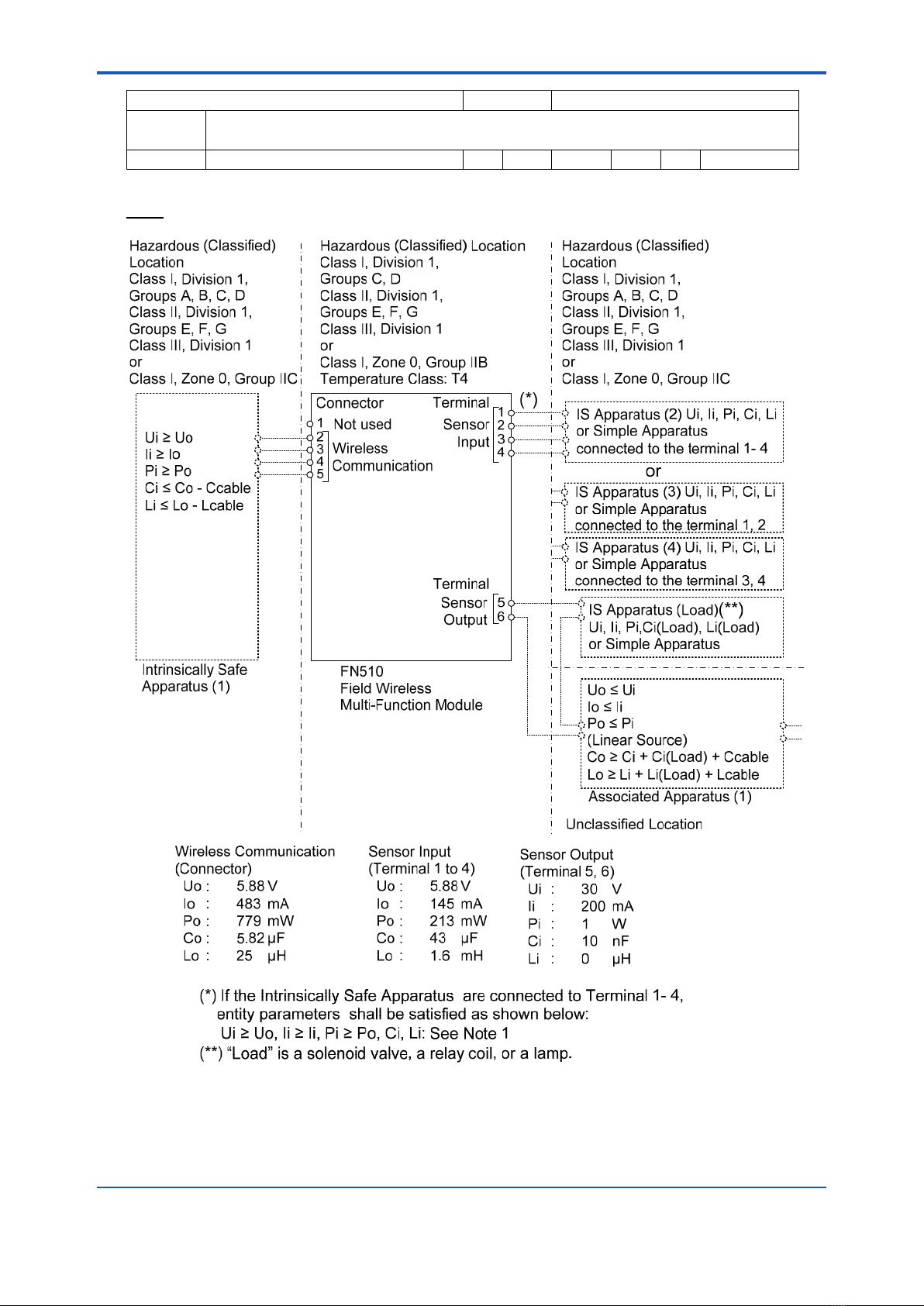
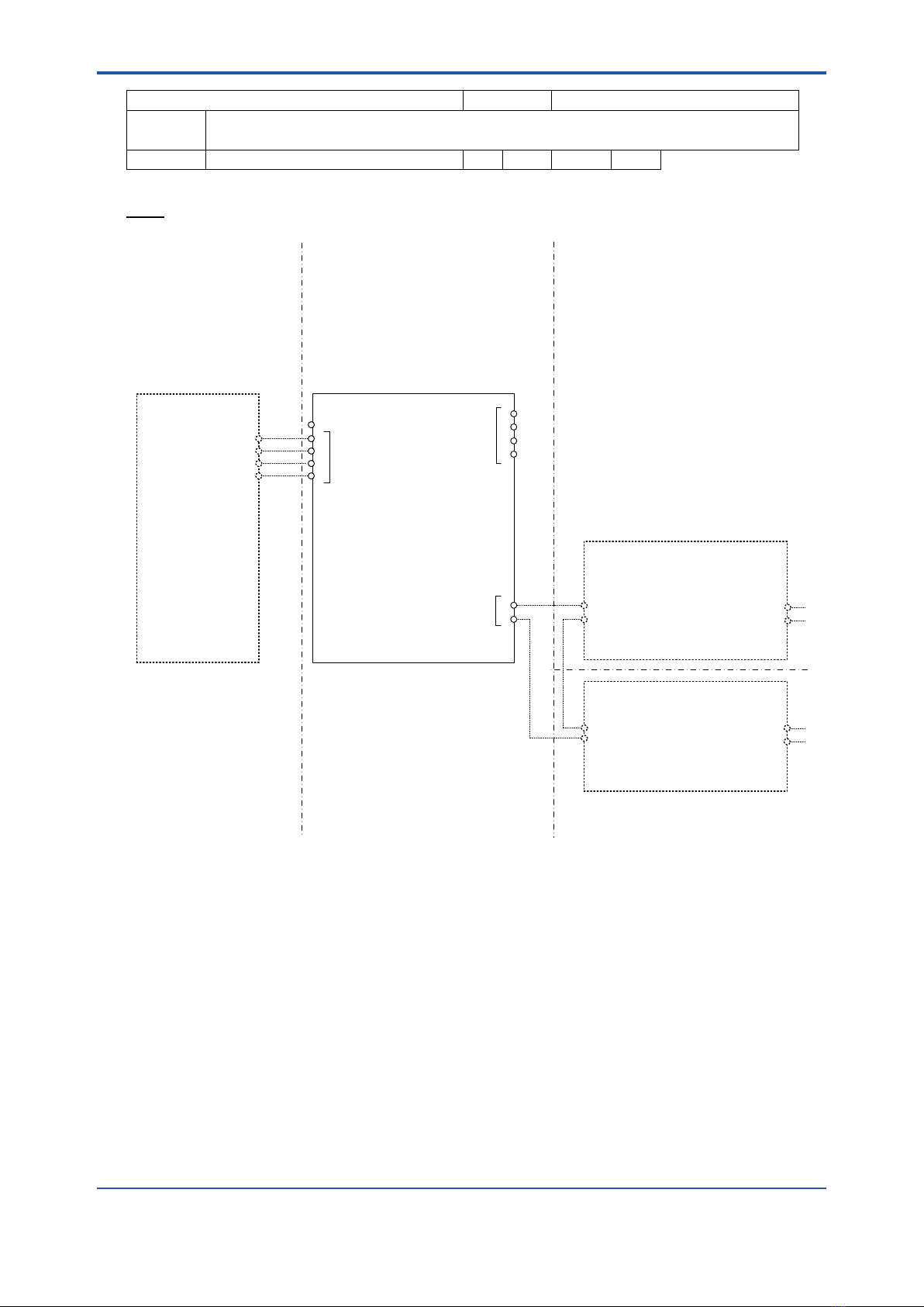
AI (1)
4
5
3
2
11
2
3
4
5
6
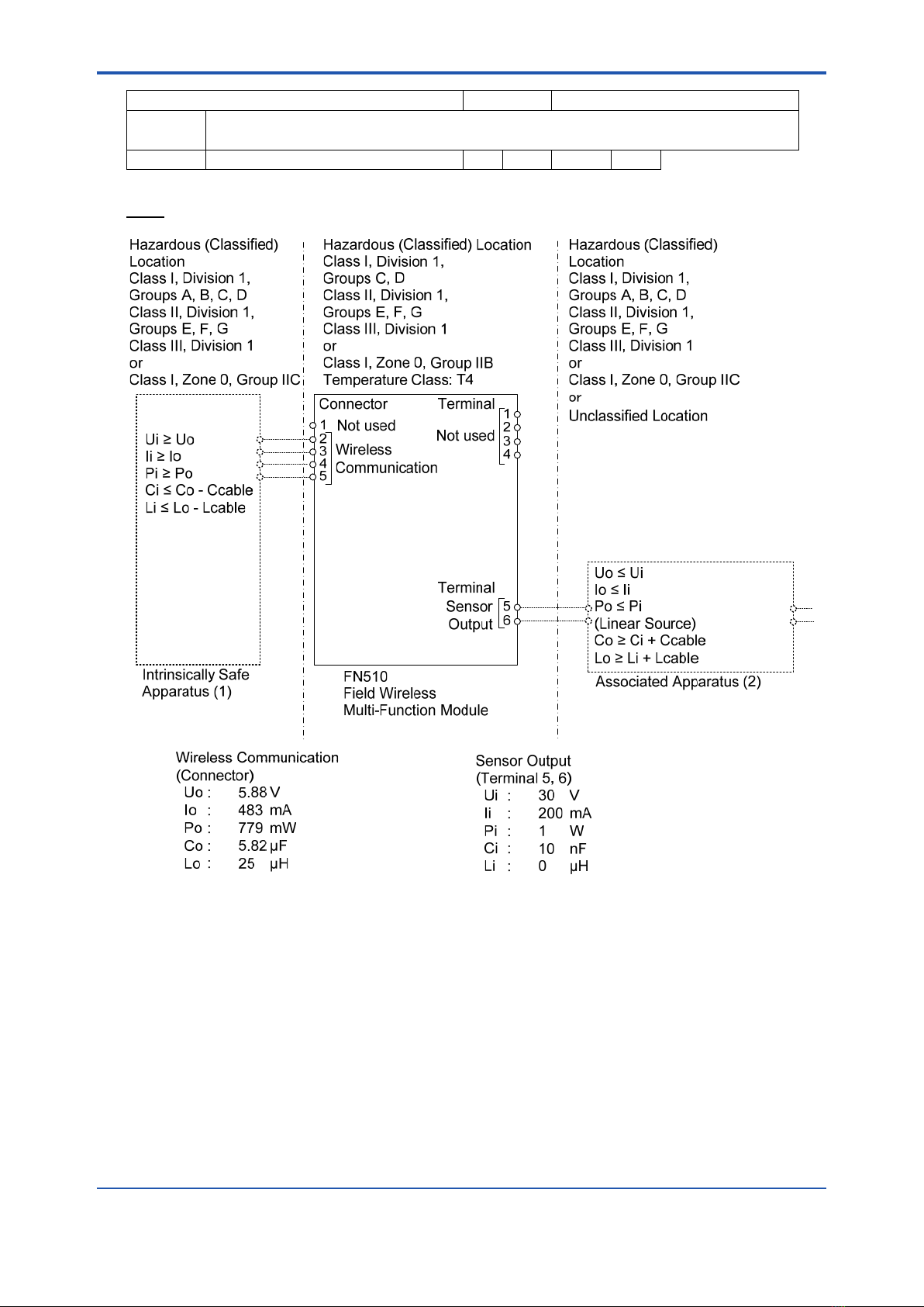
Wireless
Communication
Connector Terminal
Sensor
Output
Not used
Hazardous (Classified)
Location
Class I, Division 1,
Groups A, B, C, D
Class II, Division 1,
Groups E, F, G
Class III, Division 1
or
Class I, Zone 0, Group IIC
Hazardous (Classified) Location
Class I, Division 1,
Groups C, D
Class II, Division 1,
Groups E, F, G
Class III, Division 1
or
Class I, Zone 0, Group IIB
Temperature Class: T4
Hazardous (Classified)
Location
Class I, Division 1,
Groups A, B, C, D
Class II, Division 1,
Groups E, F, G
Class III, Division 1
or
Class I, Zone 0, Group IIC
or
Unclassified Location
Ui ≥ Uo
Ii ≥ Io
Pi ≥ Po
Ci ≤ Co - Ccable
Li ≤ Lo - Lcable
Uo ≤ Ui
Io ≤ Ii
Po ≤ Pi
(Linear Source)
Co ≥ Ci + Ci(2) + Ccable
Lo ≥ Li + Li(2) + Lcable
Associated Apparatus (1)
Unclassified Location
Wireless Communication
(Connector)
Uo : 5.88 V
Io : 483 mA
Po : 779 mW
Co : 5.82 µF
Lo : 25 µH
Sensor Output
(Terminal 5, 6)
Ui : 30 V
Ii : 200 mA
Pi : 1 W
Ci : 10 nF
Li : 0 µH
FN510
Field Wireless
Multi-Function Module
Intrinsically Safe
Apparatus (1)
Terminal
Not used
Intrinsically Safe Apparatus (2)
or
Associated Apparatus (2)
Ui(2) ≥ Uo
Ii(2) ≥ Io
Pi(2) ≥ Po
Ci(2)
Li(2)
<2. Notes on Handling> 2-7
IM 01W03E01-01EN
Yokogawa Electric Corporation Model FN510, FN310 (Modbus)
Title Control drawing of FN510 (FN510-xx-AxxA, US / Canada)
No. IFM045-A81 Page 3 Revision 1
AI (2)

<2. Notes on Handling>2-8
IM 01W03E01-01EN
Yokogawa Electric Corporation Model FN510, FN310 (Modbus)
Title Control drawing of FN510 (FN510-xx-AxxA, US / Canada)
No. IFM045-A81 Page 4 Revision 1
PULSE

<2. Notes on Handling> 2-9
IM 01W03E01-01EN
Yokogawa Electric Corporation Model FN510, FN310 (Modbus)
Title Control drawing of FN510 (FN510-xx-AxxA, US / Canada)
No. IFM045-A81 Page 5 Revision 1
Notes:
1. As allowable connection values of an Intrinsically Safe Apparatus (2) or (3) and (4), the following
conditions of (a) or (b) must be satisfied.
(a) {( Li × 100 ≤ Lo) or (Ci × 100 ≤ Co)} and {Li ≤ (Lo - Lcable) and Ci ≤ (Co - Ccable)}
(b) { Li ≤ (Lo / 2 - Lcable) and Ci ≤ (Co / 2 - Ccable)} and
[{(Ci + Ccable) ≤ 600 nF for Group IIC} or {(Ci + Ccable) ≤ 1 μF for Group IIA, IIB}]
2. (For US) No revision to this drawing without prior approval of FM.
3. (For US) Installation must be in accordance with the National Electrical Code (NFPA 70),
ANSI/ISA-RP12.06.01, and relevant local codes.
4. (For Canada) Installation must be in accordance with the Canadian Electrical Code Part I (C22.1),
ANSI/ISA-RP12.06.01, and relevant local codes.
5. (For US) IS Apparatus (or Associated Apparatus) must be FM approved.
6. Control equipment connected to IS Apparatus (or Associated Apparatus) must not use or
generate a voltage more than Um of the control equipment.
7. The equipment satisfies the requirements for IP66 and Type 4X only when it is connected to a
connector JR13WPI-5P (Hirose Electric) and tightened with a torque of 1.2-2.0 Nꞏm. Appropriate
type of plug must be used in accordance with the instructions.
8. The control drawing of IS Apparatus (or Associated Apparatus) must be followed when installing
the equipment.

<2. Notes on Handling>2-10
IM 01W03E01-01EN
2.6.2 FM Approval (Canada)
(1) Technical Data
CautionforFMApproval(Canada)Intrinsicallysafe
type.
Note1. ModelFN510FieldWirelessMulti-Function
Modulewithoptionalcode/CS17for
potentiallyexplosiveatmospheres:
• ApplicableStandards:
CAN/CSA-C22.2No.0
C22.2 No. 60079-0:19
CAN/CSA-C22.2No.60079-11:14
CAN/CSA-C22.2No.61010-1
CAN/CSA-C22.2No.94.1
CAN/CSA-C22.2No.94.2
CAN/CSA-C22.2No.60529
• Certicatenumber:FM21CA0032X
• SpecicExmarking:
Exia[iaIICGa]IIBT4Ga
ISCLI/II/IIIGPCDEFGT4
ForconnectiontoCLI/II/IIIGPABCDEFG
• Enclosure:IP66,Type4X
• Ambienttemperature:−40°C≤Ta≤+70°C
• TemperatureClass:T4
Note2. ElectricalParameters
(RefertotheControlDrawing)
Note 3. Installation
• Installationshouldbeinaccordancewith
localinstallationrequirements.
(RefertotheControlDrawing)
Note 4. Signals
Terminals:RS485Modbuscommunication
Connector:RS485Communication
Note5. Dielectricstrength
Dielectricstrength≥500VAC,r.m.s.,1min
Note6. Specicconditionsofuse
• Precautionshallbetakentominimizetherisk
fromelectrostaticdischargesonthenon-
metallicpartsoftheequipment.
• Theconnector(FN110terminal)onthe
enclosurecontainsaluminumandis
consideredapotentialriskofignitioncaused
byimpactorfriction.Whentheequipment
ismountedinZone0,itshallbeinstalledin
suchawaythat,evenintheeventofrare
incidents,anignitionsourceduetoimpact
and/orfrictionsparksisexcluded.
• Rigidtypeconduitshallnotbeusedasthe
wiringmethod.
Note7. WARNING
• Amodicationoftheequipmentwould
nolongercomplywiththeconstruction
describedinthecerticatedocumentation.
• OnlypersonnelauthorizedbyYokogawa
ElectricCorporationcanrepairthe
equipment
• USEONLYYOKOGAWABATTERYPACK
F9090FCorF9090GC
• THEBATTERYPACKCANBEREPLACED
INAHAZARDOUSLOCATION.
THEBATTERYPACKHASSURFACE
RESISTIVITYGREATERTHAN1GOHM
ANDMUSTBEPROPERLYINSTALLEDIN
THEENCLOSUREOFTHEEQUIPMENT.
CAREMUSTBETAKENDURING
TRANSPORTATIONTOANDFROMTHE
POINTOFINSTALLATIONTOPREVENT
ELECTROSTATICCHARGEBUILD-UP
• CELLSMUSTBECHANGEDINANON-
HAZARDOUSAREAONLY
• SUBSTITUTIONOFCOMPONENTSMAY
IMPAIR INTRINSIC SAFETY
• Besuretousethespeciedbatterypack
andbatteries.Fordetails,refertosection8.5
“HandlingBatteries.”
• Withanintrinsicallysafeproducts,thebattery
packisreplaceableinahazardousarea.
Duringthereplacementwork,makesurethat
dust and water droplets do not enter inside
theproducts.
Fordetailsonhowtoreplacethebattery
pack,refertosection8.3“Replacingthe
BatteryPack.”

<2. Notes on Handling> 2-11
IM 01W03E01-01EN
Yokogawa Electric Corporation Model FN510, FN310 (Modbus)
Title Control drawing of FN510 (FN510-xx-AxxA, US / Canada)
No. IFM045-A81 Page 1 Revision 1 Date 2020-09-11
DIDO

<2. Notes on Handling>2-12
IM 01W03E01-01EN
Yokogawa Electric Corporation Model FN510, FN310 (Modbus)
Title Control drawing of FN510 (FN510-xx-AxxA, US / Canada)
No. IFM045-A81 Page 2 Revision 1
AI (1)
4
5
3
2
11
2
3
4
5
6
Wireless
Communication
Connector Terminal
Sensor
Output
Not used
Hazardous (Classified)
Location
Class I, Division 1,
Groups A, B, C, D
Class II, Division 1,
Groups E, F, G
Class III, Division 1
or
Class I, Zone 0, Group IIC
Hazardous (Classified) Location
Class I, Division 1,
Groups C, D
Class II, Division 1,
Groups E, F, G
Class III, Division 1
or
Class I, Zone 0, Group IIB
Temperature Class: T4
Hazardous (Classified)
Location
Class I, Division 1,
Groups A, B, C, D
Class II, Division 1,
Groups E, F, G
Class III, Division 1
or
Class I, Zone 0, Group IIC
or
Unclassified Location
Ui ≥ Uo
Ii ≥ Io
Pi ≥ Po
Ci ≤ Co - Ccable
Li ≤ Lo - Lcable
Uo ≤ Ui
Io ≤ Ii
Po ≤ Pi
(Linear Source)
Co ≥ Ci + Ci(2) + Ccable
Lo ≥ Li + Li(2) + Lcable
Associated Apparatus (1)
Unclassified Location
Wireless Communication
(Connector)
Uo : 5.88 V
Io : 483 mA
Po : 779 mW
Co : 5.82 µF
Lo : 25 µH
Sensor Output
(Terminal 5, 6)
Ui : 30 V
Ii : 200 mA
Pi : 1 W
Ci : 10 nF
Li : 0 µH
FN510
Field Wireless
Multi-Function Module
Intrinsically Safe
Apparatus (1)
Terminal
Not used
Intrinsically Safe Apparatus (2)
or
Associated Apparatus (2)
Ui(2) ≥ Uo
Ii(2) ≥ Io
Pi(2) ≥ Po
Ci(2)
Li(2)
Other manuals for FN510
2
Table of contents
Popular Conference System manuals by other brands

Clear One
Clear One COLLABORATE Room Installation and setup manual

RF Technology
RF Technology CODE ALERT Quick Response Premiere Wireless Call... Hardware installation guide

Clear One
Clear One INTERACT PRO Specifications

Vivo Link
Vivo Link VLCAM200 manual

PTZOptics
PTZOptics PT12X-NDI-GY user manual

Clear One
Clear One XAP 800 datasheet


