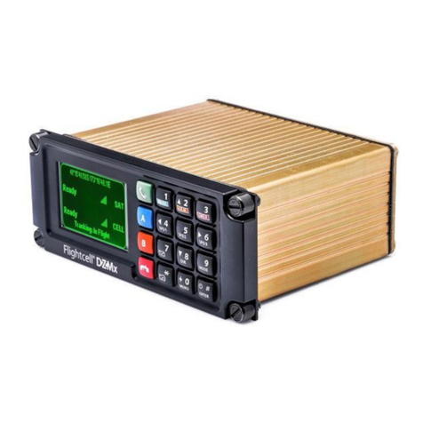
Flightcell SVS User manual

117-00002 Flightcell SVS Installation Manual Rev 1.2 Effective date 20 September 2023
Flightcell SVS
Installation Manual

117-00002 Flightcell SVS Installation Manual Rev 1.2 Effective date 20 September 2023 Page 2
Section 1: Revisions & Approvals
Manual Revision
Effective Date
Approved By
Reasons for Change
1.0
30 July 2022
James Mace
New issue for product revision 1.5
and up
1.1
30 August 2022
Brodie Hemmings-
Sykes
Updated revision
1.2
20 September
2023
Hannes Booyse
HW-2238
Except as expressly provided below, no part of this document may be reproduced, copied, transmitted, disseminated, downloaded, or
stored in any storage medium, for any purpose other than that which Flightcell International has provided this document for. Any
electronic or printed copy of this document or any revision must contain the complete text of this copyright notice. Any unauthorised
commercial distribution of this document or any revision hereto is strictly prohibited. Information in this document is subject to change.
Document users are responsible for ensuring printed copies are valid prior to use.
© Copyright 2023 Flightcell International Ltd –All Rights Reserved

117-00002 Flightcell SVS Installation Manual Rev 1.2 Effective date 20 September 2023 Page 3
CONTENTS
Section 1: Revisions & Approvals.................................................................................................... 2
Section 2: Introduction .................................................................................................................... 5
Applicability of this Manual........................................................................................................... 5
Section 3: Specifications................................................................................................................. 6
Dimensions .................................................................................................................................. 6
Electrical ...................................................................................................................................... 6
Environmental and EMI Qualifications.......................................................................................... 7
Section 4: Installation...................................................................................................................... 8
Mounting the SVS ........................................................................................................................ 8
The SVS Backplate ...................................................................................................................... 8
Necessary Installations ................................................................................................................ 8
Antennas................................................................................................................................... 9
Installation of Iridium Antennas............................................................................................................ 9
Guidelines for Antenna Cables .............................................................................................................. 9
SIM cards.................................................................................................................................. 9
SIM Slot Designation............................................................................................................................ 10
Installing SIM cards.............................................................................................................................. 10
Wiring the SVS........................................................................................................................... 10
Fabricating Wiring Harnesses ................................................................................................. 10
Grounding and Shielding Terminations ................................................................................... 10
SVS Main Connector............................................................................................................... 11
Necessary Connections ............................................................................................................. 13
Power Supply.......................................................................................................................... 13
Audio....................................................................................................................................... 13
Audio from the SVS to the Aircraft Audio System............................................................................... 13
Audio from the ICS to the SVS (microphone installation) ................................................................... 13
Low Impedance Microphones ......................................................................................................... 14
High Impedance Microphones ........................................................................................................ 14
Connecting Directly to a Headset Microphone Line.................................................................... 14
Connecting to a Cell Phone Port on the Audio Panel.................................................................. 14
Connecting to a Spare Radio Position on the Audio Panel.......................................................... 14
Inputs ...................................................................................................................................... 14
Wiring the inputs................................................................................................................................. 15
Outputs ................................................................................................................................... 15
Management Ports..................................................................................................................... 15

117-00002 Flightcell SVS Installation Manual Rev 1.2 Effective date 20 September 2023 Page 4
Section 5: Configuration................................................................................................................ 16
Accessing the Command Line Interface ..................................................................................... 16
Using the Ethernet Interface.................................................................................................... 16
Using the USB Interface.......................................................................................................... 18
Using the Command Line Interface ......................................................................................... 19
Configuring the SVS................................................................................................................ 20
Modem Configuration................................................................................................................. 20
Secondary Modem Activation.................................................................................................. 20
Safety Voice Functionality Activation....................................................................................... 21
Importing and Exporting Settings and Phone Books................................................................... 21
Settings File ............................................................................................................................ 22
Phone Book File...................................................................................................................... 22
Audio Configuration ................................................................................................................... 23
Configuring Microphone Bias .............................................................................................................. 23
Configuring Side Tone.......................................................................................................................... 23
Configuring Global Default Audio Levels............................................................................................. 23
Backlighting ............................................................................................................................... 23
Backlight Control..................................................................................................................... 23
Backlight Control Options........................................................................................................ 24
Section 6: Diagnostics................................................................................................................... 25
Real-Time Diagnostics............................................................................................................... 25
Section 7: Documentation and Information.................................................................................... 26
Contact Details........................................................................................................................... 26
Warranty .................................................................................................................................... 26

117-00002 Flightcell SVS Installation Manual Rev 1.2 Effective date 20 September 2023 Page 5
Section 2: Introduction
Thank you for selecting and purchasing a quality Flightcell product.
This manual has been prepared to guide you through the installation and configuration of your
Flightcell SVS. Please read this manual carefully before using your SVS for the first time. Keep this
manual in a safe place and use it as your first point of reference.
Due to continual product development Flightcell reserves the right to alter specifications or the
appearance of the device.
Applicability of this Manual
This manual applies to the Flightcell SVS part number HFP_01, revision 2.0 and up.
Revision 2.0 and up operate firmware version 1.2.2.

117-00002 Flightcell SVS Installation Manual Rev 1.2 Effective date 20 September 2023 Page 6
Section 3: Specifications
Dimensions
Dimension
DZUS mount
Faceplate Width
146mm
Extrusion Width
126mm
Faceplate Height
57mm
Extrusion Height
54mm
Depth (from Front face to Rear face)
110mm
Electrical
Part/Item
Parameter
Value
Power
Input Voltage
12-32VDC
Supply Current
Up to 1A @ 28VDC
ICS to SVS
Input Levels (VRMS)
20mV to 1.15V, adjustable
775mV nominal
Input Impedance
600Ω
Microphone Bias
Voltage
12V via 2.2kΩ
Output Levels (VRMS)
Up to 5V, adjustable
SVS to ICS
775mV nominal
Output Impedance
150Ω
Backlighting
Input Dimming Control
0 to 28VDC
Scaled from 0-100% based on DC input
voltage
Colour
Dual mode:
White (Daylight operation)
NVIS Green A (Night operation)
General Purpose Inputs
Inputs Levels (Vin)
0 to 28VDC
General Purpose
Outputs
Levels (Vout)
0 to 32VDC
Max Current (lout)
500mA

117-00002 Flightcell SVS Installation Manual Rev 1.2 Effective date 20 September 2023 Page 7
Environmental and EMI Qualifications
The SVS has been tested to the following DO-160G and MIL categories:
Test Name
DO160G Test Section
Cate
gory
Notes
Ground Survival Low and Short
Time Operating Low Temp
Section 4
F1
Combined test
Operating Low Temp
Section 4
F1
Combined test
Ground Survival High and Short
Time Operating High Temp
Section 4
F1
Combined test
Operating High Temp
Section 4
F1
Combined test
Altitude
Section 4
F1
Combined test
Overpressure Test
Section 4
A2
-15,000 Ft
Temperature Variation
Section 5
B
Humidity
MIL-STD-810H
Method 507.6, Procedure II
(aggravated)
Functional & Crash Hazard
Shock
MIL-STD-810H
Method 516.8, Procedure I
(functional) & Procedure V
(crash hazard)
Vibration
MIL-STD-810H
Method 514.8, Procedure I
(general), tailored per Boeing
901-910-034, Rev C,
Vibration Zone 2
Explosive Atmosphere
MIL-STD-810H
Method 511.7, Procedure I
Rain Drip
MIL-STD-810H
Method 506.6, Procedure III
Thermal Shock
MIL-STD-810H
Method 503.6, Procedure I-C
Bench Handling Shock
MIL-STD-810H
Method 516.8, Procedure VI
Blowing Dust
MIL-STD-810H
Method 510.7, Procedure I
Fungus Resistance
Section 13
F
Salt Fog
Section 14
S
Magnetic Effect
Section 15
Z
X
Power Input
Section 16
Z
X
Voltage Spike
Section 17
A
X
AF Conducted Susceptibility
Section 18
Z
X
Induced Signal Susceptibility
Section 19
AC
X
RF Conducted Susceptibility
MIL-STD-461G
Method CS114, Bulk Cable
Injection, 10KHz to 200MHz
RF Conducted Susceptibility
MIL-STD-461G
Method CS116, Damped
Sinusoidal Transients, Cables
and Power Leads
RF Conducted Susceptibility
MIL-STD-461G
Method CS117, Lightening
Induced Transients, Cables
and Power Leads
RF Susceptibility (Radiated)
MIL-STD-461G
Method RS103 2MHz to
18GHz
RF Emissions (Radiated)
MIL-STD-461G
Method RE102 10KHz to
18GHz

117-00002 Flightcell SVS Installation Manual Rev 1.2 Effective date 20 September 2023 Page 8
RF Emissions (Conducted)
Section 21
M
X
ESD
Section 25
A
X
Please contact Flightcell for more information on the Environmental an EMI Qualifications.
Section 4: Installation
Mounting the SVS
The SVS should be mounted where the flight crew or radio operator have a clear view of the
display and can easily use the keypad, preferably where there is minimal sunlight shining on the
display. The ideal location is in the panel where it is readily viewed by, and accessible to the pilot or
pilots.
If the SVS is installed in the pedestal, for ease of use it is preferable to install it as near to the front
of the pedestal as possible.
Refer to the latest versions of the mechanical drawings available from the Flightcell website at
www.flightcell.com/resources for dimensions and mounting details of for the SVS.
CAD solid model files are also available on request from Flightcell International. Contact
The SVS Backplate
All SVS connectors, and the SIM card tray, are mounted on its backplate.
Necessary Installations
The following are essential parts of the SVS installation:
»Antenna(s)
Note: The GPS Antenna BNC connector is a placeholder for future variants of the device.
This is not currently used.

117-00002 Flightcell SVS Installation Manual Rev 1.2 Effective date 20 September 2023 Page 9
»SIM Cards
Antennas
Flightcell supplies a range of antennas, the choice of which will depend on SVS modem
configuration:
»Single Iridium modem: Use a Flightcell single Iridium antenna, P/N ANP_00045
»Dual Iridium modems: Use two Flightcell single Iridium antennas, P/N ANP_00045 with a
minimum spacing of 1m between the antennas.
Installation of Iridium Antennas
Installation drawings for the antennas are available at www.flightcell.com/resources.
The Flightcell Iridium antenna should be installed on the top of the aircraft where it will have an
unrestricted view of the sky, mounted as close to horizontal as possible. The following should be
considered when determining a mounting location:
»Maintain good separation from other antennas. Preferred separation is 1m from L-band
(GPS), TCAS or transponder antennas, but a lesser separation can be applied if there is
limited space on the aircraft.
»On a helicopter, the antenna can be installed below the rotor blades, but avoid installing it
close to the rotor hub, as the hub and inner rotor can block the antenna’s view of the sky.
Keep coax cable lengths short to minimize attenuation of transmit and receive signals.
Guidelines for Antenna Cables
Iridium antenna cables must be selected to keep signal loss within accepted levels. Total signal
loss on the Iridium connection between the SVS and the antenna should not exceed -3dB at
1626MHz.
Refer to the table below for the recommended length of cables.
It is recommended that the antenna cable be reduced to RG58 for the last 300mm to the SVS to
assist with installation in the panel.
SIM cards
The SVS may have one or two Iridium modems.
The primary modem must be configured for Safety Voice Services.
The secondary modem may be configured for Safety Voice Services or may be configured for
standard Iridium services.
A SIM card is required for each Iridium modem. If the modem is used for Safety Voice Services,
then a SIM for Safety Voice Services is required. This must be obtained from an Iridium service
provider authorised to provide this service.
Cable Specification
Maximum Cable Length
RG58C/U or RG400
Up to 3m
LMR400
Up to 17m
LMR600
Up to 26m

117-00002 Flightcell SVS Installation Manual Rev 1.2 Effective date 20 September 2023 Page 10
A SIM card for standard Iridium services can be obtained from any Iridium service provider.
SIM Slot Designation
SIM card slots are allocated as follows:
»SIM 1 is allocated to the primary modem.
»SIM 2 is allocated to the secondary modem (if installed).
Installing SIM cards
SIM cards are installed in the SIM card tray inserted in the back of the SVS.
To install SIM cards:
»Undo the screws securing the SIM card tray and remove the tray.
»Preferably place the tray on the edge of a hard surface such as a ta-
ble or book.
»Position the SIM card with the bevelled corner (circled in drawing)
forward and contacts downward, then slide the front edge into the
recess in the front of the tray.
»Tilt the card downward until it clicks into the groove in the tray.
»Insert the tray into the slot on the back of the SVS and secure in
place with the two cap screws.
Wiring the SVS
Refer to the wiring diagrams for the Flightcell SVS and associated equipment (available from
www.flightcell.com/resources)
Fabricating Wiring Harnesses
All wiring should be carried out with aviation specification fireproof cable.
Screened cable should be used where indicated in the wiring diagrams. Where cable screen
connections are not explicitly shown, they should be left unterminated.
The following minimum wiring specification is recommended:
»Power supply - 22 AWG stranded (0.325mm2)
»Ethernet Cabling –CAT5e or better twisted pair cable
»USB Cabling –Up to 5m length of shielded USB Cable to ensure compliance with the USB
2.0 cable delay specification. This is essential for the operation of the USB interface.
»Other cabling - 24 AWG stranded (0.205mm2).
It is recommended that enough slack be left in the main cable to enable the SVS to be partially
removed from the aircraft panel for service or to exchange the Iridium SIM cards.
Grounding and Shielding Terminations
The SVS provides a chassis ground connection on the primary connector. This can be connected
to a local aircraft chassis ground point if required. If the SVS is mounted in a DZUS rack, the
housing is grounded to the SVS rails via the DZUS connectors and contact between the front panel
metalwork and the SVS rails.

117-00002 Flightcell SVS Installation Manual Rev 1.2 Effective date 20 September 2023 Page 11
SVS Main Connector
The SVS uses a single D38999 connector. Refer to the figure below for the layout of the SVS
backplate, connector type: D38999/24WE-35PN. The mating part is D38999/26WE-35SN (or
equivalent).
Connector Pinouts are shown in the following table.

117-00002 Flightcell SVS Installation Manual Rev 1.2 Effective date 20 September 2023 Page 12
Pin No
Name
Description
Direction
1
ETH 10/100 TX-
Ethernet port used for configuration / phonebooks
OUTPUT
2
ETH 10/100 RX+
Ethernet port used for configuration / phonebooks
INPUT
3
ETH 10/100 RX-
Ethernet port used for configuration / phonebooks
INPUT
4
AUDIO FROM SVS ICS2 LO
ICS2 Audio port
OUTPUT
5
ETH 10/100 TX+
Ethernet port used for configuration / phonebooks
OUTPUT
6
RESERVED
-
7
RESERVED
-
8
CHASSIS GND
Chassis Ground connection
CHASSIS
9
RESERVED
-
10
AUDIO FROM SVS ICS2 HI
ICS2 Audio port
OUTPUT
11
OUTPUT 3A
Output 3 - Degraded Operations
OUTPUT
12
AUDIO FROM SVS ICS1 HI
ICS1 Audio port
OUTPUT
13
OUTPUT 1B
Output 1 - Modem 1 Call Status
OUTPUT
14
OUTPUT 1A
Output 1 - Modem 1 Call Status
OUTPUT
15
OUTPUT 2B
Output 2 - Modem 2 Call Status
OUTPUT
16
RESERVED
-
17
POWER GROUND
DC Power Return
INPUT
18
OUTPUT 3B
Output 3 - Degraded Operations
OUTPUT
19
AUDIO FROM SVS ICS1 LO
ICS1 Audio port
OUTPUT
20
RESERVED
-
21
RESERVED
-
22
RESERVED
-
23
OUTPUT 2A
Output 2 - Modem 2 Call Status
OUTPUT
24
INPUT 6 (LIGHTING MODE)
Input 6 - Lighting mode input
-
25
DC IN
DC Power IN - 28VDC
INPUT
26
MIC TO SVS ICS2 HI
ICS2 Audio port
INPUT
27
MIC TO SVS ICS2 LO
ICS2 Audio port
INPUT
28
RESERVED
-
29
RESERVED
-
30
RESERVED
-
31
USB D+
USB Upgrade port
I/O
32
RESERVED
-
33
OUTPUT 4A
Reserved for future use
OUTPUT
34
MIC TO SVS 1 LO
ICS1 Audio port
INPUT
35
RESERVED
-
36
RESERVED
-
37
RESERVED
-
38
USB VBUS
USB Upgrade port
PWR
39
USB D-
USB Upgrade port
I/O
40
RESERVED
-
41
OUTPUT 4B
Reserved for future use
OUTPUT

117-00002 Flightcell SVS Installation Manual Rev 1.2 Effective date 20 September 2023 Page 13
Pin No
Name
Description
Direction
42
MIC TO SVS 1 HI
ICS1 Audio port
INPUT
43
INPUT GND
Input Ground return
-
44
RESERVED
-
45
RESERVED
-
46
USB GND
USB Upgrade port
GROUND
47
RESERVED
-
48
RESERVED
-
49
INPUT GND
Input Ground return
Ground
50
INPUT 2
Input 2 - EMCON Mode
INPUT
51
INPUT 1
Input 1 - Aural Notification Suppression
INPUT
52
INPUT 5 (LIGHTING)
Input 5 - Lighting level input 0-28VDC Signal
INPUT
53
INPUT 3
Input 3 - Modem 1 Call Answer/Terminate
INPUT
54
INPUT 4
Input 4 - Modem 2 Call Answer/Terminate
INPUT
55
INPUT GND
Input Ground return
GROUND
Necessary Connections
»Power Supply
»Audio System
»Inputs
»Outputs
Power Supply
The SVS unit and other components require aircraft DC power. Operating range is 12-32VDC. It is
recommended that the SVS be connected to the emergency (primary) power bus on the aircraft.
This is to ensure successful operation of emergency calls.
When operating on a nominal 28V supply, a 2-amp circuit breaker/fuse is recommended to protect
the SVS system.
The SVS has a non-resettable internal 5A fail-safe fuse to protect the aircraft power bus from major
malfunctions.
Audio
Audio from the SVS to the Aircraft Audio System
The SVS supports an isolated audio channel for each of the Iridium SATVOICE channels installed
in the unit. Audio from the SVS is connected direct to the ICS input, and its levels adjusted using
the SVS setting.
Audio from the ICS to the SVS (microphone installation)
The SVS can be installed in aircraft systems with either high impedance or low impedance
microphones. Most (but not all) civil aircraft operate high impedance (electret) microphone
systems. Most (but not all) military aircraft operate low impedance microphone systems. Refer to
www.flightcell.com/resources for wiring diagrams for the microphone connections.

117-00002 Flightcell SVS Installation Manual Rev 1.2 Effective date 20 September 2023 Page 14
Low Impedance Microphones
When installing the SVS with an ICS that uses low impedance mics, the SVS must be connected to
a line level Radio/Comms port. If a line-level port is not available and the SVS is to be connected
direct to the mic line, then a tactical radio adaptor will be needed to match impedances. Options
include the NAT AA34-300, Jupiter JA34-001 or PS Engineering 200-002-0002.
High Impedance Microphones
There are several options for connecting the SVS into an audio panel/ICS with high impedance
microphones. The way in which the SVS is connected will depend on your system configuration
and operational requirements. As the Iridium satellite phones are full duplex, it is preferable to use
the SVS on a hot mic connection, rather than PTT (keyed). The SVS will typically be installed in
one of the following ways:
Connecting Directly to a Headset Microphone Line
The MIC lines are spliced to one or more headset microphone inputs on the audio panel. As these
microphone inputs have mic bias provided by the audio panel, the SVS should have mic bias
disabled. The way this is configured will depend on how many headsets are to have access to the
SVS:
If only the pilot is to use the SVS, its MIC TO SVS 1 HI/LO lines are connected only to the pilot’s
microphone line.
If both pilot and co-pilot are to use the SVS, the MIC lines are connected to the pilot microphone
line and the MIC lines are connected to the co-pilot microphone line.
If more than two microphones need to have access to the SVS, an external switch is required to
select the active microphone input.
Connecting to a Cell Phone Port on the Audio Panel
The SVS MIC line can be connected to the cell phone port on the audio panel.
Connecting to a Spare Radio Position on the Audio Panel
On aircraft with separate audio control panels at each crew position, this option enables crew to
use the SVS and connected phones individually on demand. In this case it may be necessary to
provide mic bias.
Inputs
The SVS has six Inputs which are assigned the following functions:
Input
Number
Input type
Input function
1
Digital
Audio Annunciation Suppression Mode Enable
2
Digital
EMCON mode Enable
3
Digital
Primary Comms Answer/End
4
Digital
Secondary Comms Answer/End
5
Analog
Backlight Dimming
6
Digital
Backlight Day/Night Mode

117-00002 Flightcell SVS Installation Manual Rev 1.2 Effective date 20 September 2023 Page 15
Wiring the inputs
The inputs can tolerate a voltage range of 0-28VDC, with an over/under voltage protection to
±32VDC. The inputs have two states, Open (high voltage) or Closed (low voltage). Refer to the
Flightcell website at www.flightcell.com/resources. for the wiring diagrams.
Two ground return pins are provided for the five primary GPIs (pin 3 and pin 17 of the primary
connector); these are internally connected to power ground and aircraft chassis ground, so the
aircraft chassis can be used as a ground return for these GPIs if required.
Outputs
The SVS has four outputs, which are switches that can be used to turn an electrical signal on or off.
These can each be wired to a light on the aircraft panel.
Each output has two terminals, A and B. The output consists of an isolated switch, internal to the
SVS. When the output is active, the switch is closed (terminals A and B are connected). When
output is inactive, the switch is open (terminals A and B are disconnected).
Output functions are assigned as follows:
Output
Number
Description
Off State
Toggling State
On State
1
Primary Comms Call state
Idle
Incoming Call
In Call
2
Secondary Comms Call
state
Idle
Incoming Call
In Call
3
Degraded Operations and
EMCON state
Device is operating in
a degraded capacity
EMCON mode
is enabled
Device is
operating normally
4
Reserved
Management Ports
In order to configure the SVS, and to export and import settings files and phonebooks, a
management port is required.
The SVS has two management ports, Ethernet and USB.
»The Ethernet port can be used for configuration and to export and import settings files and
phonebooks
»The USB port can be used as a backup port for configuration only.
Management ports can be installed either on the aircraft, or on a management loom in the
workshop.
Wiring of the management ports is shown in the SVS Wiring Diagrams.

117-00002 Flightcell SVS Installation Manual Rev 1.2 Effective date 20 September 2023 Page 16
Section 5: Configuration
A number of settings on the SVS can be user configured via a connected PC using the Command
Line Interface.
Accessing the Command Line Interface
The Command Line Interface is usually accessed over the SVS Ethernet connection but can also
be accessed over the SVS USB connection.
Using the Ethernet Interface
The Ethernet Interface on the SVS uses a static IP address and does not support DHCP. The host
PC connected to the SVS needs to have an ethernet interface statically configured in the same IP
address range as the SVS to provide access to the telnet and web server functionality.
The following are steps to configure a Windows PC to connect to the SVS.
1: Connect the SVS ethernet interface via an RJ45 cable to an ethernet port on the host PC.
2: In the windows search bar type in Network Connections.
3: Select the networking interface the SVS is connected to (usually named Ethernet) and select
properties.

117-00002 Flightcell SVS Installation Manual Rev 1.2 Effective date 20 September 2023 Page 17
4: Select “Internet Protocol Version 4 (TCP/Ipv4)” and press the Properties button to open the IP
address configuration window.
5: Select “Use the following IP Address” and enter the parameters shown in the following image:
6: Press OK to apply the configuration.
Note: If the configured Ethernet port is the primary port for the PC, it should be reset to
“Obtain an IP address automatically” in step 5 to access the internet when SVS
configuration is complete.

117-00002 Flightcell SVS Installation Manual Rev 1.2 Effective date 20 September 2023 Page 18
Once the host PC is connected to the SVS, open Putty or a similar Telnet compatible client, select
the Telnet protocol and connect to the address 169.254.1.1.
Using the USB Interface
1: Connect a PC to the SVS via the USB connection
2: Open a serial terminal to the SVS com port using a serial terminal client such as Putty. In
Windows, the correct COM port to select can be found using the Device Manager. In the windows
search bar type in Device Manager.

117-00002 Flightcell SVS Installation Manual Rev 1.2 Effective date 20 September 2023 Page 19
Using the Command Line Interface
Upon connecting to the command line interface, the following will be presented:
Commands can be input one at a time, using the ENTER key to execute the command. To show a
list of commands use the help command which will output the following:
Note: It is not necessary to set the serial configuration such as baud rate.

117-00002 Flightcell SVS Installation Manual Rev 1.2 Effective date 20 September 2023 Page 20
Configuring the SVS
To view a list of all settings and their current values, the show-settings command can be used
which will present the following:
To change a setting use the set command with the setting name and a value which is either YES or
NO for Boolean settings or an integer value.
For example, to change the Maximum brightness of the NVIS keypad backlight the following
command would be entered:
Modem Configuration
The SVS can be configured with one or two Iridium 9523 Satellite modems for use with either the
ATS Safety Voice network or the standard Iridium SATVOICE network.
The default modem configuration for the SVS is:
»Primary modem –configured for Safety Voice Services
»Secondary modem (if installed) –configured for standard Iridium services.
Secondary Modem Activation
The secondary modem on the SVS can be enabled or disabled via a setting depending on the
number of modems installed. This will be pre-configured prior to shipment, unless otherwise
requested.
To activate or deactivate the secondary modem set the following setting to YES or NO respectively.
»MODEM_2_ENABLE
Other manuals for SVS
1
Table of contents
Other Flightcell Conference System manuals
Popular Conference System manuals by other brands

RADVision
RADVision Scopia XT5000 Series Administrator's guide

Polycom
Polycom realpresence 1800 Administrator's guide

Cisco
Cisco Quick Set C20 Quick reference guide
Crestron
Crestron UC-M50-T quick start

Takstar
Takstar DG-C100R Installation instruction
GE
GE MobileLink CB-1000 Installation and troubleshooting guide

