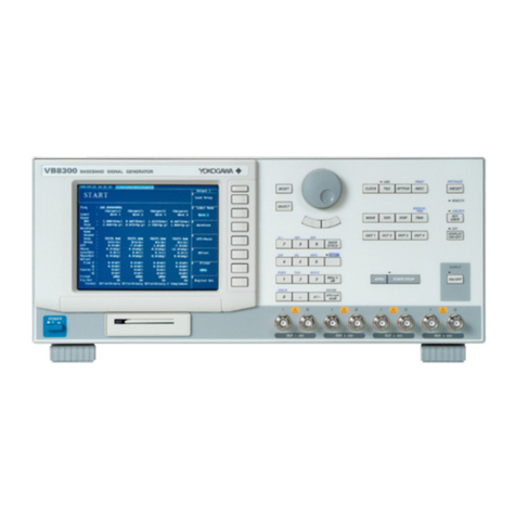
YOKOGAWA FG420 User manual

User's
Manual
FG410/FG420
Arbitrary/Function Generator
User’s Manual(Basic)
IM FG410-01EN
6th Edition
nbn Austria GmbH

User Registration
YOKOGAWA provides registered users with useful information and services. Please
allow us to serve you best by completing the user registration form accessible from
our website.
https://tmi.yokogawa.com/support/
Contact Us
If you want to resolve a technical support issue or need to contact YOKOGAWA,
please fill out the inquiry form on our website.
https://tmi.yokogawa.com/contact/
PIM 103-06E

I
IM FG410-01EN
Preface
Thank you for purchasing the FG410/FG420 Arbitrary/Function Generator.
To ensure safe and proper use of this electric equipment, please read first Safety Precautions on the
following pages.
● CautionSymbolsUsyasu6905edinThisManual
The following caution symbols are used in this manual. Be sure to observe these caution symbols and
their contents to ensure the safety of the user and avoid damage to the equipment.
WARNING
Thismarkindicatesinformationfortheavoidanceofahazardsuchas
electricshockthatmayendangerhumanlifeorcauseinjuryduring
handlingoftheequipment.
AVERTISSEMENT
Cesigneindiquedesinformationsvisantàéviterlesaccidentstelsque
leschocsélectriquesrisquantdeprovoquerdesblessuresoulamort
lorsdel’utilisationdel’équipement.
CAUTION
Thismarkindicatesinformationfortheavoidanceofdamagetothe
equipmentduringhandling.
ATTENTION
Cesigneindiquedesinformationspermettantd’éviterd’endommager
l’appareillorsdesonutilisation.
● AboutManuals
This manual focuses on the handling precautions, basic operations, and specifications of the FG410/
FG420.
To ensure correct use, please read this manual thoroughly before beginning operation. Keep this
manual in a safe place for quick reference in the event that a question arises.
The following nine manuals, including this one, are provided as manuals for the FG410/FG420.
Please read all manuals.
ManualTitle Manual No. Description
FG410/FG420 Arbitrary/Function
Generator User's Manual(Basic)
IM FG410-01EN This manual. Explains the handling precautions
and basic operations of the FG410/FG420 and
provides a list of specifications.
FG410/FG420 Arbitrary/
Function Generator User's
Manual(Application)
IM FG410-02EN Explains all FG410/FG420 features, except for
the communication features, and how to use
them.
FG410/FG420 Arbitrary/Function
Generator Communication Interface
User's Manual
IM FG410-17EN Explains the features related to using
communication commands to control the
FG410/FG420.
FG410/FG420 ARBITRARY
WAVEFORM EDITOR User's
Manual
IM FG410-61EN Explains ARBITRARY WAVEFORM EDITOR
features, and how to use them.
FG410/FG420 SEQUENCE EDIT
SOFTWARE User's Manual
IM FG410-62EN Explains SEQUENCE EDIT SOFTWARE
features, and how to use them.
FG410/FG420 LabVIEW Driver
SOFTWARE User's Manual
IM FG410-63EN Explains LabVIEW Driver SOFTWARE
features, and how to use them.

II IM FG410-01EN
FG410/FG420 Transferring and
Outputting DLM/DL/SL Series
Waveform Data
IM FG410-64EN Explains how to transfer waveform data acquired
with an DLM/DL/SL series instrument to the
FG410/FG420 and use it to generate arbitrary
waveforms.
FG410/FG420 Arbitrary/Function
Generator
IM FG410-92Z1 For Chinese
Safety Instruction Manual IM 00C01C01-01Z1 Safety manual (European languages)
Contact information of Yokogawa offices worldwide is provided on the following sheet.
Manual No. Description
PIM113-01Z2 List of worldwide contacts
● Thismanualhasthefollowingchapterorganization.
Instruction manuals of the FG410/FG420 are divided to two volumes, Basics and Application.
Instructions for remote control (GPIB and USB) are provided separately.
If reading this manual for the first time, start from 1. OVERVIEW of the Basics Instruction Manual.
Basics
1. OVERVIEW
Briefly describes and explains the features and brief operation principles of the FG410/FG420.
2. PREPARATIONSBEFOREUSE
Describes various cautions regarding preparations to be made before using the FG410/FG420,
ranging from installation to connection of the power supply.
3. PANELSANDI/OTERMINALS
Describes the functions and operations of the switches and I/O terminals of the panel controls.
4. BASICOPERATION
Describes how to use basic functions.
5. SAVINGANDRECALLINGSETTINGS
Describes how to store and retrieve the settings.
6. LISTOFINITIALSETTINGS
Describes initial settings.
7. SPECIFICATIONS
Lists the specifications (functions and performance) of the FG410/FG420.
8. RECOMMENDEDPARTREPLACEMENT
List of recommended part replacement

III
IM FG410-01EN
Application
1. DETAILSOFPARAMETER-VARIABLEWAVEFORMS
Explains the meanings of each parameter of parameter-variable waveforms and waveform
examples.
2. CREATINGARBITRARYWAVEFORMS
Explains how to input and edit arbitrary waveforms from the panel control.
3. HANDYUSEOF2-CHANNELDEVICE(FG420ONLY)
Explains how to operate two channels at the same time.
4. SYNCHRONIZINGMULTIPLEUNITS
Describes how to configure a multi-phase oscillator by connecting multiple units of this product.
5. USINGEXTERNALFREQUENCYREFERENCE
Describes how to use external frequency reference.
6. USINGSEQUENCEOSCILLATION
Describes how to set and operate sequence oscillation.
7. USINGUSER-DEFINEDUNITS
Explains the units that can be optionally set by users.
8. OTHERUTILITYSETTINGS
Explains how to set display and operational details.
9. TROUBLESHOOTING
Explains error messages and how to respond to cases where a failure is suspected.
10.MAINTENANCE
Explains the operational inspection and performance test.

IV IM FG410-01EN
SafetyPrecautions
This product is designed to be used by a person with specialized knowledge.
To ensure safe use, be sure to observe the following warnings and cautions.
Yokogawa Test & Measurement Corporation shall not be held liable for damages that arise from a
failure to observe these warnings and cautions.
This product is a Class I product (with protective conductor terminal) that conforms to the JIS and
IEC insulation standards.
This manual is part of the product and contains important information. Store this manual in a safe
place close to the instrument so that you can refer to it immediately. Keep this manual until you
dispose of the instrument.
● UsetheInstrumentOnlyforItsIntendedPurpose
The FG410/FG420 is designed to generate sine waveforms, rectangular waveforms, and other various
types of voltage waveforms. Use the FG410/FG420 only for this purpose.
● CheckthePhysicalAppearance
Do not use the instrument if there is a problem with its physical appearance.
● Besuretoobservethecontentsofthisinstructionmanual.
This instruction manual contains information for the safe operation and use of this product.
Be sure to read this information first before using this product.
All the warnings in the instruction manual must be heeded to prevent hazards that may cause major
accidents.
● Besuretogroundtheproduct.
This product uses a line filter and must be grounded to avoid the risk of electric shock.
To prevent electric shock, be sure to safely implement grounding such that ground resistance is 100
W or lower.
The FG410/FG420 is automatically grounded when the 3-prong power plug is connected to a 3-prong
power outlet with a protective grounding contact.
● Checkthepowersupplyvoltage.
This product operates on the power supply voltage shown in 2.3 Grounding and Power Supply
Connection in the Basics Instruction Manual.
Prior to connecting the power supply, check that the voltage of the power supply matches the rated
power supply of the product.
● Incaseofsuspectedanomaly
If this product emits smoke, an abnormal smell, or abnormal noise, immediately power it off and stop
using it.
If such an anomaly occurs, do not use this product until it has been repaired, and immediately report
the problem to the location of purchase (either YOKOGAWA or your distributor).
● Donotusethisproductwhengasispresent.
An explosion or other such hazard may result.
● Donotremovethecover.
This product contains high-voltage parts. Absolutely never remove its cover.
Even when the inside of this product needs to be inspected, do not touch the inside. All such
inspections are to be performed by service technicians designated by YOKOGAWA.
● Donotmodifythisproduct.
Absolutely never modify this product, as this may cause new hazards and may disqualify this product
from repair in case of failure.
● InstallorUsetheInstrumentinAppropriateLocations
• This instrument is designed to be used indoors. Do not install or use it outdoors.
• Install the instrument so that you can immediately remove the power cord if an abnormal or
dangerous condition occurs.

V
IM FG410-01EN
French
● NefaitesdecetéquipementQUEl’utilisationpourlaquelleilaétéconçu
Le FG410/FG420 est conçu pour générer des formes d’ondes sinusoïdales, des formes d’ondes
rectangulaires et d'autres types de formes d’ondes de tension. Utilisez le FG410/FG420 à cette fin
uniquement.
● Inspectezl'apparencephysique
N’utilisez pas l'équipement si son intégrité physique semble être compromise.
● Respecteztoujourslesinstructionsduprésentmoded’emploi.
Ce mode d’emploi contient des informations pour un fonctionnement et une utilisation sûrs de ce
produit.
Veillez à bien lire ces informations avant d’utiliser ce produit.
Respectez tous les avertissements de ce mode d’emploi afin d’éviter les dangers susceptibles de
provoquer des accidents graves.
● Veillezàrelierl’appareilàlaterre.
Cet appareil est équipé d’un filtre en ligne et doit être relié à la terre pour éviter les risques de choc
électrique.
Pour éviter les risques de choc électrique, veillez à bien relier l’appareil à la terre de manière à obtenir
une résistance de terre inférieure ou égale à 100 .
Le FG410/FG420 est automatiquement relié à la terre lorsque l’on branche la fiche secteur à 3
broches sur une prise d’alimentation à 3 boches équipée d'un contact de mise à la terre de protection.
● Contrôlezlatensiond’alimentationélectrique.
Cet appareil fonctionne sur la tension d’alimentation électrique indiquée à la section 2.3 Raccord à la
terre et branchement d’alimentation
électrique du mode d’emploi de base.
Avant le branchement sur l’alimentation électrique, vérifiez que la tension d’alimentation électrique
correspond à l’alimentation électrique préconisée sur l’appareil.
● Encasd’anomalieprésumée
Si cet appareil émet de la fumée, une odeur anormale, ou un son inhabituel, débranchez-le
immédiatement, et ne l’utilisez pas.
En cas d’anomalie de ce type, n’utilisez pas ce produit tant qu’il n’a pas été réparé, et signalez
immédiatement le problème au personnel du lieu d'achat (YOKOGAWA ou votre distributeur)."
● N’utilisezpasceproduitencasdeprésencedegaz.
Ceci risquerait de provoquer une explosion ou d’autres dangers similaires.
● N’ouvrezpaslecouvercle.
Cet appareil contient des pièces sous haute tension. N’ouvrez le couvercle sous aucun prétexte.
Ne touchez jamais l’intérieur de cet appareil, même lorsqu’il doit être inspecté. Confiez toujours ce
type d’inspection aux techniciens de service désignés par YOKOGAWA.
● Nemodifiezpascetappareil.
Ne modifiez cet appareil sous aucun prétexte, car ceci risquerait d’entraîner des risques
supplémentaires et pourrait rendre le produit impropre à la réparation en cas de panne.
● Installezetutilisezcetéquipementdansdeslieuxappropriés
• Cet appareil est conçu pour une utilisation à l’intérieur. Ne l’installez/utiliser pas à l'extérieur.
• Installez l'équipement de manière à pourvoir le débrancher immédiatement du secteur en cas de
fonctionnement anormal ou dangereux.

VI IM FG410-01EN
● Safety-relatedsymbols
The general definitions of the safety-related symbols used on this product and in the instruction
manual are provided below.
Instruction Manual Reference Symbol
This symbol is displayed to alert the user to potential danger and refer him/her to
the instruction manual.
Electric Shock Danger Symbol
This symbol indicates locations that present a risk of electric shock under specific
conditions.
WARNING
Warning Symbol
This symbol indicates information for avoiding danger to human life or bodily
injury while handling this product.
AVERTISSEMENT
Symbole d'avertissement
Ce symbole indique des informations permettant d'éviter les accidents ou la mort
lors de l'utilisation de ce produit.
CAUTION
Caution Symbol
This symbol indicates information for preventing damage to the product when
handling it.
ATTENTION
Symbole de mise en garde
Ce symbole indique des informations permettant d'éviter d'endommager l'appareil
lors de son utilisation.
● Othersymbols
This symbol indicates that the external conductor of the connector is connected to the case.
This symbol shows that the external conductor of the connector is insulated from the case.
It shows, however, that the potential difference from the grounding potential is restricted to 42
Vpk or lower for safety. (Since this product is grounded when used, the potential of the case
equals the grounding potential.)
● Wastedisposal
When disposing of the instrument, follow the laws and ordinances of your country or region.

VII
IM FG410-01EN
Waste Electrical and Electronic Equipment (WEEE)
(EU WEEE Directive valid only in the EEA*and UK WEEE Regulation in the UK)
This product complies with the WEEE marking requirement. This marking indicates that you
must not discard this electrical/electronic product in domestic household waste.
When disposing of products in the EEA or UK, contact your local Yokogawa office in the EEA
or UK respectively.
* EEA: European Economic Area
Authorized Representative in the EEA
Yokogawa Europe B.V. is the authorized representative of Yokogawa Test & Measurement
Corporation for this product in the EEA. To contact Yokogawa Europe B.V., see the separate list of
worldwide contacts, PIM 113-01Z2.
關於在台灣銷售
This section is valid only in Taiwan.
關於在台灣所販賣的符合其相關規定的電源線 A1100WD 的限用物質含量信息,請至下麵的
網址進行查詢
https://tmi.yokogawa.com/support/service-warranty-quality/product-compliance/

VIII IM FG410-01EN

IX
IM FG410-01EN
Contents
Preface..............................................................................................................................I
Safety Precautions ........................................................................................................ IV
Waste Electrical and Electronic Equipment .................................................................. VII
Authorized Representative in the EEA.......................................................................... VII
關於在台灣銷售............................................................................................................. VII
1. OVERVIEW...................................................................................................................1
1.1 Features..................................................................................................................1
1.2 Operating Principles ...............................................................................................2
2. PREPARATIONSBEFOREUSE ...........................................................................4
2.1 Checking Before Use..............................................................................................4
2.2 Installation...............................................................................................................6
2.3 Grounding and Power Supply Connection..............................................................8
2.4 Calibration...............................................................................................................9
3. PANELSANDI/OTERMINALS ...........................................................................10
3.1 Panel Components and Operations .....................................................................10
3.1.1 Front panel of FG410 .................................................................................10
3.1.2 Rear panel of FG410 ..................................................................................11
3.1.3 Front panel of FG420 .................................................................................12
3.1.4 Rear panel of FG420 ..................................................................................13
3.2 I/O Terminals.........................................................................................................14
3.2.1 Waveform output (FCTN OUT) ..................................................................15
3.2.2 Sync/sub-output (SYNC/SUB OUT) ..........................................................15
3.2.3 External modulation/addition input (MOD/ADD IN) ...................................16
3.2.4 External trigger input (TRIG IN) .................................................................17
3.2.5 External 10 MHz frequency reference input (10 MHz REF IN) ..................17
3.2.6 Frequency reference output (REF OUT) ...................................................18
3.2.7 Multi-I/O (MULTI I/O) .................................................................................19
3.3 Cautions on Floating Ground Connection.............................................................22
4. BASICOPERATION ................................................................................................25
4.1 Power on/off Switching and Restoration of Settings.............................................25
4.1.1 Power on/off switching method...................................................................25
4.1.2 Restoration of settings at power-on ...........................................................26
4.2 Screen Configuration and Operation ...................................................................29
4.2.1 Screen configuration...................................................................................29
4.2.2 Switching display format with tabs (displaying waveform graph) ...............31
4.2.3 Top menu ...................................................................................................33

XIM FG410-01EN
4.3 Basic Settings and Operations .............................................................................34
4.3.1 Changing the frequency, amplitude, and other values................................34
4.3.2 Changing the waveform and oscillation mode............................................37
4.3.3 Manipulating shortcut keys for changing basic parameters .......................38
4.3.4 Operations of ENTER key, CANCEL key, and UNDO key .........................39
4.3.5 Changing the display unit ...........................................................................40
4.3.6 CH1/CH2 switching key and active channel (FG420 only).........................42
4.3.7 Actions possible in the Utility screen ..........................................................43
4.3.8 Restoring the initial settings........................................................................45
4.3.9 Output on/off...............................................................................................45
4.4 Setting Methods for Main Items ............................................................................47
4.4.1 Configuration of text display screen in continuous oscillation mode ..........47
4.4.2 Setting the oscillation mode........................................................................47
4.4.3 Setting the waveform..................................................................................48
4.4.4 Setting the frequency..................................................................................48
4.4.5 Performing setting with period ....................................................................49
4.4.6 Setting the phase........................................................................................49
4.4.7 Setting the amplitude..................................................................................52
4.4.8 Setting DC offset.........................................................................................54
4.4.9 Setting the output level with high level/low level.........................................55
4.4.10 Setting the waveform polarity and amplitude range ...................................56
4.4.11 How to use auto range/range hold for the output voltage...........................58
4.4.12 Setting the load impedance ........................................................................59
4.4.13 Adding external signal ................................................................................61
4.4.14 Setting the square wave duty .....................................................................63
4.4.15 Setting the pulse width and leading/trailing edge time of a pulse wave .....65
4.4.16 Setting the ramp wave symmetry ...............................................................68
4.5 Using Parameter-Variable Waveforms..................................................................69
4.6 Using Arbitrary Waveforms ...................................................................................71
4.7 Modulation Setting and Manipulation....................................................................73
4.7.1 Modulation types ........................................................................................73
4.7.2 Screen for modulation setting and manipulation ........................................74
4.7.3 Common modulation settings and manipulations.......................................76
4.7.4 Setting FM ..................................................................................................79
4.7.5 Setting FSK ................................................................................................80
4.7.6 Setting PM ..................................................................................................81
4.7.7 Setting PSK ................................................................................................82
4.7.8 Setting AM ..................................................................................................83
4.7.9 Setting AM (DSB-SC) .................................................................................84
4.7.10 Setting DC offset modulation......................................................................85
4.7.11 Setting PWM...............................................................................................86

XI
IM FG410-01EN
4.8 Sweep Setting and Manipulation ..........................................................................87
4.8.1 Sweep types ...............................................................................................87
4.8.2 Screen for sweep setting and manipulation................................................87
4.8.3 Common sweep settings and manipulations ..............................................90
4.8.4 Setting frequency sweep ............................................................................99
4.8.5 Setting phase sweep ................................................................................101
4.8.6 Setting amplitude sweep ..........................................................................103
4.8.7 Setting DC offset sweep ...........................................................................105
4.8.8 Setting duty sweep ...................................................................................107
4.9 Burst Setting and Manipulation...........................................................................109
4.9.1 Burst oscillation types...............................................................................109
4.9.2 Auto burst .................................................................................................110
4.9.3 Trigger burst ............................................................................................. 113
4.9.4 Gate oscillation .........................................................................................117
4.9.5 Triggered gate oscillation..........................................................................122
5. SAVINGANDRECALLINGSETTINGS ..........................................................126
5.1 Saving Settings...................................................................................................126
5.2 Recalling Settings ...............................................................................................128
6 LISTOFINITIALSETTINGS ..............................................................................130
7. SPECIFICATIONS ..................................................................................................133
7.1 Oscillation Modes ...............................................................................................133
7.2 Waveforms..........................................................................................................133
7.2.1 Standard waveforms.................................................................................133
7.2.2 Arbitrary waveforms..................................................................................133
7.3 Frequency, Phase...............................................................................................134
7.4 Output Characteristics ........................................................................................134
7.4.1 Amplitude..................................................................................................134
7.4.2 DC offset...................................................................................................134
7.4.3 Load impedance setting ...........................................................................135
7.4.4 Waveform output ......................................................................................135
7.4.5 Sync/sub output........................................................................................135
7.5 Signal Characteristics .........................................................................................135
7.5.1 Sine wave .................................................................................................135
7.5.2 Square wave.............................................................................................136
7.5.3 Pulse wave ...............................................................................................136
7.5.4 Ramp wave...............................................................................................137
7.5.5 Parameter-variable waveforms.................................................................137
7.6 Modulated Oscillation Mode ...............................................................................140
7.6.1 General.....................................................................................................140
7.6.2 Modulation conditions...............................................................................141

XII IM FG410-01EN
7.7 Sweep Oscillation Mode .....................................................................................142
7.7.1 General.....................................................................................................142
7.7.2 Sweep conditions .....................................................................................143
7.8 Burst Oscillation Mode........................................................................................143
7.9 Triggers...............................................................................................................144
7.10 Sequence............................................................................................................145
7.11 Other I/Os ...........................................................................................................146
7.12 2-channel ganged operation (FG420 only).........................................................147
7.13 Synchronous Operation of Multiple Units ...........................................................148
7.14 User-Defined Units .............................................................................................148
7.15 Other Functions ..................................................................................................149
7.16 Options ...............................................................................................................149
7.17 General Characteristics ......................................................................................149
External dimensions (FG410)..........................................................................151
External dimensions (FG420)..........................................................................152
RACK MOUNTING DIMENSIONS...............................................................................153
Inch rack mounting dimensions (for 1 unit)......................................................153
Inch rack mounting dimensions (for 2 units)....................................................154
Millimeter rack mounting dimensions (for 1 unit) .............................................155
Millimeter rack mounting dimensions (for 2 units) ...........................................156
8. RECOMMENDEDPARTREPLACEMENT.....................................................158
INDEX ...................................................................................................................................160
FiguresandTables
Figure 3-1. Front Panel of FG410...........................................................................10
Figure 3-2. Rear Panel of FG410............................................................................11
Figure 3-3. Front Panel of FG420...........................................................................12
Figure 3-4. Rear Panel of FG420............................................................................13
Figure 3-5. Multi-I/O Connector Pin Assignment ....................................................20
Figure 3-6. Cautions on Floating Ground Connection for FG410 ..........................23
Figure 3-7. Cautions on Floating Ground Connection for FG420 ...........................24
Table 3.1 Signals Selectable for Sync/Sub-Output .................................................15
Table 3-2. Multi-I/O Connector Function Allocation ................................................20

1
IM FG410-01EN
1. OVERVIEW
1.1 Features
The FG410 and FG420 are arbitrary/function generator based on direct digital synthesizers (DDS).
The FG410 is a 1-channel generator, while the FG420 is a two-channel generator.
• Highest frequency: 30 MHz (sine wave), 15 MHz (square wave, pulse)
• Frequency accuracy: ±(3 ppm + 2 pHz), high resolution of 0.01 μHz. 10 MHz external frequency
reference can be used.
• Maximum output voltage: 20 Vp-p/open, 10 Vp-p/50 Ω
• Large number of standard parameter-variable waveforms: Sine wave, square wave (variable duty),
pulse (variable pulse width/duty, leading edge time, trailing edge time), ramp wave (variable
symmetry), CF controlled sine wave (variable crest factor), staircase sine wave (variable number
of steps), Gaussian pulse (variable s), Sin(x)/x (variable number of zero crossings), exponential
rise/fall (variable time constant), damped oscillation (variable oscillation frequency, damping time
constant), pulse surge (variable rising and duration times), trapezoid (variable rise, fall, and upper
base width), and so on.
• Large-capacity arbitrary waveform memory: 512 K words max., saving capacity: 128 waveforms/4
M words
• Phase and waveform remain continuous even when frequency is changed or during frequency
sweep.
• Square wave, pulse with variable duty and high resolution of 0.0001%
• Pulse with variable leading edge time and trailing edge time
• Various oscillation modes
• Continuous oscillation
• Modulation: FM, FSK, PM, PSK, AM, DC offset modulation, PWM
• Sweep: Frequency, phase, amplitude, DC offset, duty
• Burst oscillation: Auto burst, trigger burst, gate oscillation, triggered gate oscillation
• Sequence oscillation: Variable waveform/ frequency/ phase/ amplitude/ DC offset/ square wave
duty, constant value/ linear interpolation, jump/ repeat/ hold/ branch
• Sequence function for easy test waveform creation and adjustment
Flexible waveform creation possible through combination with standard parameter-variable
waveforms
Frequency, phase, amplitude, etc., can be rapidly changed and swept
• Intuitive user interface through use of high-resolution QVGA TFT color LCD
• Two-channel ganged function with 2 phases, constant frequency difference, constant frequency
ratio, and differential output (only FG420)
• Floated from housing for each channel to reduce effect of ground loop
• Multiple-phase oscillator can be configured by synchronizing multiple units
• USB and GPIB interfaces provided
• Thin and lightweight: Height of approx. 9 cm, weight of approx. 2.1 kg

2IM FG410-01EN
1.OVERVIEW
1.2 Operating Principles
FG410 blockdiagram
ANALOG
REF OUT
TRIG IN
10MHz REF IN
for ANALOG
+12V
100V...230V
~LINE
MOD/ADD
IN
FCTN
OUT
SYNC/SUB
OUT
A/DLPF
LPF
D/A
DC OFFSET
120MHz
±10Vmax
PGA
0/-10/-20/-30dB
LPF
±1V
×2
TTL/±3V
×5
±2Vmax
EXTERNAL
MODULATION
EXTERNAL
ADDITION
ISOLATION
DDS
WAVE
MEMORY
16bit
512Kw
16bit-
2CH
D/A
CLOCK
GENERATOR
20MHz
SYSTEM
CONTROLLER
MULTI
I/O
GPIBUSB
FRONT
PANEL
UNIT
AC/DC
POWER
SUPPLY
FAN
for SYSTEM
CONTROLLER
Analog block
• The DDS (digital direct synthesizer) uses a 120 MHz clock to generate various types of oscillation
and waveforms. Modulation, sweep, burst, and sequence are also processed within the DDS.
• The digital waveforms generated by the DDS are controlled to the specified polarity (normal,
inversed) in the amplitude range (-FS/0, ±FS, 0/+FS), and following digital amplitude adjustment,
the signal is input into the digital to analog (D/A) converter.
• The waveform converted into an analog signal by the D/A is then smoothed by the lowpass filter
(LFP), and the amplitude is controlled in 10 dB steps by the programmable gain amplifier (PGA).
• The external addition signal and DC offset are added to the PGA output. When an output voltage
exceeding ±2V/open is required, output is done via the ×5 amplifier.
• The maximum output voltage of the product is either 20 Vp-p or 4 Vp-p depending on whether or
not the ×5 amplifier is used. Also depending on this, the external addition gain is either ×10 or ×2.
• After passing through the LPF, the external modulation signal undergoes A/D conversion and is
then input to the DDS.

3
IM FG410-01EN
FG420 blockdiagram
ANALOG CH1
AC/DC
FAN
for ANALOG CH1
+12V
~LINE
100V...230V
for ANALOG CH2
REF OUT
TRIG IN CH1
10MHz REF IN
TRIG IN CH2
ANALOG CH2
MOD/ADD
IN
FCTN
OUT
SYNC/SUB
OUT
A/DLPF
LPF
DDS
D/A
DC OFFSET
16bit
512Kw
WAVE
MEMORY
120MHz
±10Vmax
PGA
0/-10/-20/-30dB
LPF
±1V
×2
TTL/±3V
×5
±2Vmax
EXTERNAL
MODULATION
EXTERNAL
ADDITION
ISOLATION
POWER
SUPPLY
for SYSTEM
CONTROLLER
20MHz
SYSTEM
CONTROLLER
MULTI
I/O
GPIBUSB
FRONT
PANEL
UNIT
16bit-
2CH
D/A
CLOCK
GENERATOR
• The analog block is insulated from the system controller block located in the housing potential.
• In the FG420, the analog block comprises two channels, each individually isolated from the
housing potential.
Systemcontrollerblock
• This block performs control of the analog block, including the display, panel key processing,
remote control (GPIB, USB) processing, trigger input processing, frequency reference control,
DDS control, amplitude, and DC offset.
• A 20 MHz crystal oscillator is used as the basic oscillation of the DDS.
• The signal to synchronize multiple units is sent to REF OUT (frequency reference output), and the
inter-channel sync (FG420 only) is sent to the analog block of each channel.
Power supply block
• The AC/DC directly connected to the power supply input is in a constantly powered state.
• Control of each power supply circuit is done through power switch manipulation.
1.2 Operating Principles

4IM FG410-01JA
2. PREPARATIONSBEFOREUSE
2.1 CheckingBeforeUse
a) Safetycheck
To ensure safety in using the FG410/FG420, the user should read the following sections of this
instruction manual before using the FG410/FG420:
• Safety Precautions (provided at the beginning of this instruction manual)
• 2.3 Grounding and Power Supply Connection
b) Appearanceandaccessoriescheck
If an abnormality (such as a flaw or dent) is found on the outside surface of the corrugated box,
carefully check if the product is adversely affected when removing the product from the corrugated
box.
After opening the corrugated box, check the items contained in the box.
If an abnormality such as a flaw or dent is found on the product, or an accessory is missing, contact
YOKOGAWA or its representative.
• Model
Check that the product that you received is what you ordered by referring to the model name and
suffix code given on the delivery note on the packing box. The suffix code of the power cord is not
indicated on the instrument.
MODEL Suffix Description
FG410 Arbitrary/Function Generator: 1-Channel, 30 MHz
FG420 Arbitrary/Function Generator: 2-Channel, 30 MHz
Power cord1
-D
-F
-Q
-R
-H
-N
-T
-B
-U
-Y
UL/CSA Standard power cord, Maximum rated voltage: 125 V
VDE Standard power cord, Maximum rated voltage: 250 V
BS Standard power cord, Maximum rated voltage: 250 V
AS Standard power cord, Maximum rated voltage: 250 V
GB Standard power cord, Maximum rated voltage: 250 V
NBR Standard power cord, Maximum rated voltage: 250 V
Taiwanese Standard power cord, Maximum rated voltage: 125 V
Indian Standard power cord, Maximum rated voltage: 250 V
IEC Plug Type B power cord, Maximum rated voltage: 250 V
No power cord included.2
1 Make sure that the attached power cord meets the designated standards of the country and area that you are using it in.
2 Prepare a power cord that complies with the standard specified by the country or region that the instrument will be used
in.
• Appearance check
Check that no abnormalities such as a flaw and dent are found on the panel, controls, connectors, and
so forth.

5
IM FG410-01EN
• Configurationandaccessory check
The accessories of this product are listed below. Check that there are no missing items and no flaws
are found.
Main unit ‧‧‧‧‧‧‧‧‧‧‧‧‧‧‧‧‧‧‧‧‧‧‧‧‧‧‧‧‧‧‧‧‧‧‧‧‧‧‧‧‧‧‧‧‧‧‧‧‧‧‧‧‧‧‧‧‧‧‧‧‧‧‧‧‧‧‧‧‧‧‧‧‧‧‧‧‧‧‧‧‧‧‧‧‧‧‧‧‧‧‧‧‧‧‧‧‧‧‧‧‧‧‧‧‧‧‧‧‧‧‧‧‧‧‧‧‧‧‧‧‧‧‧‧‧‧‧‧‧‧‧‧‧‧‧‧‧‧‧‧‧ 1
Instruction Manual (Basics IM FG410-01EN) ‧‧‧‧‧‧‧‧‧‧‧‧‧‧‧‧‧‧‧‧‧‧‧‧‧‧‧‧‧‧‧‧‧‧‧‧‧‧‧‧‧‧‧‧‧‧‧‧‧‧‧‧‧‧‧‧‧‧‧‧‧‧‧‧‧‧‧‧‧‧‧‧‧‧‧‧‧‧‧‧‧‧‧‧‧‧‧ 1
Inquiries (PIM 113-01Z2) ‧‧‧‧‧‧‧‧‧‧‧‧‧‧‧‧‧‧‧‧‧‧‧‧‧‧‧‧‧‧‧‧‧‧‧‧‧‧‧‧‧‧‧‧‧‧‧‧‧‧‧‧‧‧‧‧‧‧‧‧‧‧‧‧‧‧‧‧‧‧‧‧‧‧‧‧‧‧‧‧‧‧‧‧‧‧‧‧‧‧‧‧‧‧‧‧‧‧‧‧‧‧‧‧‧‧‧‧‧‧‧‧‧‧‧‧‧‧‧1
FG410/FG420 Arbitrary / Function Generator (IM FG410-92Z1) ‧‧‧‧‧‧‧‧‧‧‧‧‧‧‧‧‧‧‧‧‧‧‧‧‧‧‧‧‧‧‧‧‧‧‧‧‧‧‧‧‧‧‧‧‧‧‧‧‧‧‧‧‧‧‧‧1
Safety Instruction Manual (IM 00C01C01-01Z1) ‧‧‧‧‧‧‧‧‧‧‧‧‧‧‧‧‧‧‧‧‧‧‧‧‧‧‧‧‧‧‧‧‧‧‧‧‧‧‧‧‧‧‧‧‧‧‧‧‧‧‧‧‧‧‧‧‧‧‧‧‧‧‧‧‧‧‧‧‧‧‧‧‧‧‧‧‧‧‧‧‧‧ 1
CD (PDF instruction manuals, application software) ‧‧‧‧‧‧‧‧‧‧‧‧‧‧‧‧‧‧‧‧‧‧‧‧‧‧‧‧‧‧‧‧‧‧‧‧‧‧‧‧‧‧‧‧‧‧‧‧‧‧‧‧‧‧‧‧‧‧‧‧‧‧‧‧‧‧‧‧‧‧‧‧‧‧‧‧‧1
PDF instruction manuals:
Arbitrary & Function Generator User's Manual(Application).pdf
IM FG410-02EN
Communication Interface User's Manual.pdf IM FG410-17EN
ARBITRARY WAVEFORM EDITOR User's Manual.pdf
IM FG410-61EN
SEQUENCE EDIT SOFTWARE User's Manual.pdf IM FG410-62EN
LabVIEW Driver SOFTWARE User's Manual.pdf IM FG410-63EN
Transferring and Outputting DLMDLSL Series Waveform Data.pdf IM FG410-64EN
Application software:
Arbitrary Waveform Editing Software, Sequence Editing Software,
LabVIEW Driver
Power cord set (2 m, with 3-prong plug) ‧‧‧‧‧‧‧‧‧‧‧‧‧‧‧‧‧‧‧‧‧‧‧‧‧‧‧‧‧‧‧‧‧‧‧‧‧‧‧‧‧‧‧‧‧‧‧‧‧‧‧‧‧‧‧‧‧‧‧‧‧‧‧‧‧‧‧‧‧‧‧‧‧‧‧‧‧‧‧‧‧‧‧‧‧‧‧‧‧‧‧‧‧‧‧‧ 1
Suffix Part No. SpecificationsandNotes
-D A1006WD UL, CSA, and PSE standard
-F A1009WD VDE standard
-Q A1054WD BS standard
-R A1024WD AS standard
-H A1064WD GB standard
-N A1088WD NBR standard
-T A1100WD Taiwanese standard
-B A1101WD Indian standard
-U A1102WD IEC Plug Type B
Make sure that the attached power cord meets the designated standards of the country and area
that you are using it in. If the suffix code is -Y, a power cord is not included.
• DoNotDamagethePowerCord
Nothing should be placed on top of the power cord, and it should be kept away from any heat sources.
When removing the plug from the power outlet, do not pull on the cord. Pull from the plug. If the
power cord is damaged or if you are using the instrument in a location where the power supply
specifications are different, purchase a power cord that matches the specifications of the region that
the instrument will be used in.
WARNING
This product contains high-voltage parts. Never remove the cover.
All internal inspections of this product are to be performed only by
service technicians qualified by Yokogawa Test & Measurement
Corporation.
2.1 Checking Before Use

6IM FG410-01EN
2.PREPARATIONS BEFORE USE
AVERTISSEMENT
Cet appareil contient des pièces sous haute tension. N'ouvrez jamais
le couvercle. Toute inspection interne de cet appareil doit être effectuée
exclusivement par des techniciens de service qualifiés par Yokogawa
Test & Measurement Corporation.
c) Repacking
When repacking this equipment for transportation, etc., use a shipping carton of sufficient strength
and capacity to safely accommodate the equipment and hold its weight.
d) Options
The following options are available and can be purchased separately.
Model/partsnumber Product Description
705928 Multi input/output cable For sweep/sequence control
751537-E2 Rack mount kit Inch rack mounting (for 1 unit)
751537-J2 Rack mount kit Millimeter rack mounting (for 1 unit)
751538-E2 Rack mount kit Inch rack mounting (for 2 units)
751538-J2 Rack mount kit Millimeter rack mounting (for 2 units)
• Multi-I/O cable
This cable is used when using the multi-I/O connector on the rear panel.
A 2 meter multi-core shielded cable is connected to the mini-Dsub 15-pin connector. Since the
opposite side is cut off, process that side according to the connection destination.
For the connector's pin assignment and cable differentiation, p. 20 .
• Rack mount adapters
These adapters are for mounting the equipment on a 19-inch IEC, EIA standard rack, or JIS
standard rack.
Each type of adapter is available as a 1-unit and 2-unit model (for side-by-side mounting), for a
total lineup of 4 models.
2.2 Installation
CAUTION
Operating Environment Limitations
This product is a Class A (for industrial environments) product.
Operation of this product in a residential area may cause radio
interference in which case the user will be required to correct the
interference.
ATTENTION
Limitations relatives à l'environnement opérationnel
Ce produit est un produit de classe A (pour environnements industriels).
L'utilisation de ce produit dans un zone résidentielle peut entraîner une
interférence radio que l'utilisateur sera tenu de rectifier.
This manual suits for next models
2
Table of contents
Other YOKOGAWA Portable Generator manuals
Popular Portable Generator manuals by other brands
Briggs & Stratton
Briggs & Stratton 5000 Watt Operator's manual
Rohde & Schwarz
Rohde & Schwarz 1141.2005.02 quick start guide

Briggs & Stratton
Briggs & Stratton PowerBoss 030217 Wiring diagrams
HP
HP 8340b manual
SDMO
SDMO KOHLER PERFORM 3000 C5 Instruction and maintenance manual

Amico
Amico AH6000LN owner's manual
