YOKOGAWA 700938 User manual

User’s
Manual 700938
Power Supply
IM 700938-01E
7th Edition

User Registration
YOKOGAWA provides registered users with useful information and services. Please
allow us to serve you best by completing the user registration form accessible from
our website.
https://tmi.yokogawa.com/support/
Contact Us
If you want to resolve a technical support issue or need to contact YOKOGAWA,
please fill out the inquiry form on our website.
https://tmi.yokogawa.com/contact/
PIM 103-06E

1
IM 700938-01E
Thank you for purchasing the 700938 Power Supply. This user’s manual
contains useful information about the instrument’s functions and operating
procedures as well as precautions that should be observed during use. To
ensure proper use of the instrument, please read this manual thoroughly before
operating it. Keep the manual in a safe place for quick reference whenever a
question arises.
List of Manuals
The following manuals are provided for the 700938 Power Supply.
Manual Title Manual No. Notes
700938 Power Supply
User’s Manual
IM 700938-01E This manual.
Model 700938 Power Supply
User’s Manual
IM 700938-92 Document for China
Model 700938 Power Supply
User’s Manual
IM 700938-93Z2 Document for Korea
The “E” and “Z2” in the manual numbers are the language codes.
Contact information of Yokogawa offices worldwide is provided on the following
sheet.
Document No. Description
PIM113-01Z2 List of worldwide contacts
Revisions
1st Edition: May 1999
2nd Edition: January 2001
3rd Edition: November 2005
4th Edition: November 2015
5th Edition: October 2017
6th Edition: July 2019
7th Edition: April 2021
7th Edition: April 2021 (YMI)
All Rights Reserved, Copyright © 1999 Yokogawa Electric Corporation
All Rights Reserved, Copyright © 2015 Yokogawa Test & Measurement Corporation

2IM700938-01E
Checking the Contents of the Package
If the worng instrument or accessories have been delivered, if some accessories
are missing or if they appear abnormal, contact the dealer form which you
purchased them.
700938 Power Supply (main unit)
MODEL Suffix Description
700938 Main device
Power supply
voltage
-1 90 to 110 VAC
-3 108 to 132 VAC
-5 198 to 242 VAC
-7 216 to 264 VAC
Power cord1-D UL/CSA standard, maximum rated voltage: 125 V
-F VDE standard, maximum rated voltage: 250 V
-R SAA standard, maximum rated voltage: 250 V
-Q BS standard, maximum rated voltage: 250 V
-H Chinese standard, maximum rated voltage: 250 V
-N Brazilian standard, maximum rated voltage: 250 V
-T Taiwanese standard, maximum rated voltage: 125 V
-B Indian standard, maximum rated voltage: 250 V
-U IEC Plug Type B, maximum rated voltage: 250 V
-Y No power cord included.2
1 Make sure that the attached power cord meets the designated standards of the
country and area that you are using it in.
2 Prepare a power cord that complies with the standard specified by the country or
region that the instrument will be used in.
Standard Accessories
Item Model or Part No. Quantity Specifications and Notes
Power cord* A1006WD
A1009WD
A1024WD
A1054WD
A1064WD
A1088WD
A1100WD
A1101WD
A1102WD
1 UL/CSA standard
VDE standard
SAA standard
BS standard
Chinese standard
Brazilian standard
Taiwanese standard
Indian standard
IEC Plug Type B
Spare fuse — 1 • 100 V, 120 V: F1.0 AL/250 V, 20 mm ×
5 mm dia.
• 220 V, 240 V: F0.5 AL/250 V, 20 mm ×
5 mm dia.
Manuals IM 700938-01E 1 User’s Manual (this guide)
IM 700938-92 1 Document for China
IM 700938-93Z2 1 Document for Korea
PIM 113-01Z2 1 List of worldwide contacts
Standard accessories are not covered by warranty.
* Make sure that the attached power cord meets the designated standards of the
country and area that you are using it in. If the suffix code is -Y, a power cord is not
included.
3
IM 700938-01E
Safety Precautions
This product is designed to be used by a person with specialized knowledge.
This instrument is an IEC safety class I instrument (provided with terminal for
protective grounding).
The following general safety precautions must be observed during all phases
of operation, service and repair of this instrument. If this instrument is used in a
manner not specified in this manual, the protection provided by this instrument
may be impaired. YOKOGAWA assumes no liability for the customer’s failure to
comply with these requirements.
This manual is part of the product and contains important information. Store
this manual in a safe place close to the instrument so that you can refer to it
immediately. Keep this manual until you dispose of the instrument.
Operating Environment and Conditions
This instrument complies with the EMC standard under specific operating
environment and operating conditions. If the installation, wiring, and so on are
not appropriate, the compliance conditions of the EMC standard may not be
met. In such cases, the user will be required to take appropriate measures.
The following symbols are used on this instrument.
Warning: handle with care. Refer to the user’s manual or service manual.
This symbol appears on dangerous locations on the instrument which require
special instructions for proper handling or use. The same symbol appears in
the corresponding place in the manual to identify those instructions.
Ground or the functional ground terminal (do not use as the protective
earth ground terminal)
Alternating current
ON (power)
OFF (power)
French
Avertissement : À manipuler délicatement. Toujours se reporter aux manuels
d’utilisation et d’entretien. Ce symbole a été apposé aux endroits dangereux
de l’instrument pour lesquels des consignes spéciales d’utilisation ou
de manipulation ont été émises. Le même symbole apparaît à l’endroit
correspondant du manuel pour identifier les consignes qui s’y rapportent.
Borne de terre ou borne de terre fonctionnelle (ne pas utiliser cette borne
comme prise de terre.)
Courant alternatif
Marche (alimentation)
Arrêt (alimentation)
4IM700938-01E
Safety Precautions
Precautions
In order to ensure safe operation and to obtain maximum performance from the
unit, observe the cautions listed below.
WARNING
Use the Correct Power Cord and Plug
To prevent the possibility of electric shock or fire, be sure to use the power
cord for the instrument. The main power plug must be plugged into an
outlet with a protective earth terminal. Do not invalidate this protection by
using an extension cord without protective earth grounding. Further, do not
use this power cord with other instruments.
Connect the Protective Ground Terminal
Be sure to connect the protective earth to prevent electric shock before
turning ON the power. The power cord that you can use for the instrument
is a three-prong cord. Connect the power cord to a properly grounded
three-prong outlet.
CAUTION
• Do not subject the unit to vibrations or shocks during transport or
handling. Be especially careful to avoid dropping the unit.
• Do not store the unit where it will be exposed to direct sunlight, high
temperature, high humidity, or condensation. If exposed to such
conditions, the unit may be damaged, the insulation may deteriorate,
and the unit may no longer satisfy its specifications.
• Before using the unit, inspect it and check the operation to make
sure that the unit was not damaged due to poor storage or transport
conditions. If damage is found, contact your dealer or YOKOGAWA
representative.
• Nothing should be placed on top of the power cord, and it should be kept
away from any heat sources. When removing the plug from the power
outlet, do not pull on the cord. Pull from the plug. If the power cord is
damaged or if you are using the instrument in a location where the power
supply specifications are different, purchase a power cord that matches
the specifications of the region that the instrument will be used in.
• This unit is not constructed to be waterproof or dustproof, so do not use
it in a very dusty environment or in one where it will get wet.
• Gently wipe dirt from the surface of the unit with a soft cloth moistened
with a small amount of water or mild detergent. Do not try to clean
the unit using cleaners containing organic solvents such as benzine,
alcohol, acetone, ether, ketones, thinners, or gasoline. They may cause
discoloration or damage.
5
IM 700938-01E
Safety Precautions
French
AVERTISSEMENT
Utiliser le cordon d’alimentation et la fiche adaptés
Pour éviter tout risque de choc électrique, utiliser exclusivement le cordon
d’alimentation prévu pour cet instrument. La fiche doit être branchée sur
une prise secteur raccordée à la terre. En cas d’utilisation d’une rallonge,
celleci doit être impérativement reliée à la terre. Par ailleurs, ne pas utiliser
ce cordon d’alimentation avec d’autres instruments.
Brancher la prise de terre
Avant de mettre sous tension, veiller à brancher la mise à la terre de
protection afin d’éviter les chocs électriques. Le cordon d’alimentation que
vous utilisez pour l’instrument est un cordon à trois broches.
Brancher le cordon d’alimentation sur une prise de courant à trois plots et
mise à la terre.
ATTENTION
• Ne pas soumettre l’appareil à des vibrations ou des chocs lors du
transport ou de la manipulation. Il faut être particulièrement attentif à ne
pas faire chuter l’appareil.
• Ne pas stocker l’appareil dans un endroit où il sera exposé aux rayons
directs du soleil, à une température élevée, à une humidité élevée ou à
la condensation. L’exposition à de telles conditions risque d’endommager
l’appareil, détériorer l’isolation de l’appareil et l’appareil risque de ne
plus répondre à ses spécifications.
• Veuillez effectuer une inspection avant toute utilisation de l’appareil
et vérifiez son fonctionnement pour vous assurer qu’il n’a pas été
endommagé en raison de mauvaises conditions de stockage ou de
transport. En cas de dommages, contactez votre revendeur ou votre
représentant YOKOGAWA.
• Rien ne doit être placé sur le cordon d’alimentation et il faut le tenir
à l’écart de toute source de chaleur. Ne pas retirer le cordon lorsque
vous débranchez la prise de courant. Tirez de la fiche. Si le cordon
d’alimentation est endommagé ou si vous utilisez l’instrument dans
un emplacement où les spécifications d’alimentation sont différentes,
achetez un cordon d’alimentation conformément aux spécifications de
l’emplacement où l’instrument sera utilisé.
• Cet appareil n’est pas conçu pour être étanche à l’eau ou à la
poussière. Par conséquent, ne pas l’utiliser dans un environnement très
poussiéreux ou dans un environnement où il sera humide.

6IM700938-01E
• Essuyez délicatement la saleté de la surface de l’appareil avec un
chiffon doux légèrement imprégné d’eau ou de détergent doux. Ne pas
tenter de nettoyer l’appareil avec des produits de nettoyage contenant
des solvants organiques comme le benzène, l’alcool, l’acétone, l’éther,
les cétones, les diluants ou l’essence. Ces produits risquent d’entraîner
une décoloration ou des dommages.
Regulations and Sales in Various Countries and Regions
Waste Electrical and Electronic Equipment
Waste Electrical and Electronic Equipment (WEEE), Directive
(This directive is valid only in the EU.)
This product complies with the WEEE directive marking
requirement. This marking indicates that you must not discard this
electrical/electronic product in domestic household waste.
Product Category
With reference to the equipment types in the WEEE directive, this
product is classified as a “Monitoring and control instruments”
product.
When disposing of products in the EU, contact your local Yokogawa
Europe B.V. office.
Do not dispose in domestic household waste.
Authorized Representative in the EEA
Yokogawa Europe B.V. is the authorized representative of Yokogawa Test &
Measurement Corporation for this product in the EEA. To contact Yokogawa
Europe B.V., see the separate list of worldwide contacts, PIM 113-01Z2.
關於在台灣銷售
This section is valid only in Taiwan.
關於在台灣所販賣的符合其相關規定的電源線 A1100WD 的限用物質含量信息,
請至下麵的網址進行查詢
https://tmi.yokogawa.com/support/service-warranty-quality/product-compliance/
Disposal
When disposing of YOKOGWA products, follow the laws and ordinances of the
country or region where the product will be disposed of.
Safety Precautions

7
IM 700938-01E
The following symbol marks are used to attract the operator’s attention.
Improper handling or use can lead to injury to the user or
damage to the instrument. This symbol appears on the
instrument to indicate that the user must refer to the user’s
manual for special instructions. The same symbol appears in
the corresponding place in the user’s manual to identify those
instructions. In the manual, the symbol is used in conjunction
with the word “WARNING” or “CAUTION.”
WARNING Calls attention to actions or conditions that could cause serious
or fatal injury to the user, and precautions that can be taken to
prevent such occurrences.
CAUTION Calls attention to actions or conditions that could cause
light injury to the user or damage to the instrument or user’s
data, and precautions that can be taken to prevent such
occurrences.
French
AVERTISSEMENT Attire l’attention sur des gestes ou des conditions susceptibles
de provoquer des blessures graves (voire mortelles), et sur les
précautions de sécurité pouvant prévenir de tels accidents.
ATTENTION Attire l’attention sur des gestes ou des conditions susceptibles
de provoquer des blessures légères ou d’endommager
l’instrument ou les données de l’utilisateur, et sur les
précautions de sécurité susceptibles de prévenir de tels
accidents.
Note Calls attention to information that is important for proper
operation of the instrument.

8IM700938-01E
Contents
List of Manuals..................................................................................................................1
Checking the Contents of the Package.............................................................................2
Safety Precautions............................................................................................................3
Regulations and Sales in Various Countries and Regions................................................6
Product Overview..............................................................................................................9
Names of Parts .................................................................................................................9
Measurement Procedure ................................................................................................10
Preparations ........................................................................................................10
Measurement Procedure .....................................................................................10
Fuse Replacement ......................................................................................................... 11
Specifications..................................................................................................................14
Product Specifications .........................................................................................14
Compliant Standards ...........................................................................................14
Corrective Action to be Taken in the case of an Abnormality..........................................14

9
IM 700938-01E
Product Overview
This instrument is a power supply for probes.
Two power connectors are provided on the front panel, and this allows two
probes to be used simultaneously.
Names of Parts
Made in Japan
MODEL
NO.
POWER SUPPLY
POWER
PROBE
1 2
Power
connectors
Fuse holderPower indicator
Power supply
connector
Voltage
viewing
window
ON
Power
switch
OFF
Grounding terminal
Front view Rear view
1 Not used
2 +12V
3 -12 V
4 GND
14
3 2
Power connector pin assignments
10 IM700938-01E
Measurement Procedure
Measurement Procedure
Preparations
CAUTION
Before turning on the power, make sure that the voltage of the power
supply being used matches the supply voltage indicated on the rear panel
of the unit.
French
ATTENTION
Avant la mise sous tension, assurez-vous que la tension de l’alimentation
utilisée corresponde à la tension indiquée sur le panneau arrière de
l’appareil.
1Turn the power switch off and connect the power cord.
2Insert the power supply plug for the DL Series probe that you are using
into the power connector on this instrument.
3Turn the power switch ON, and check that the front panel power indicator
lights.
Measurement Procedure
Refer to the user’s manual on how to use the various probes.
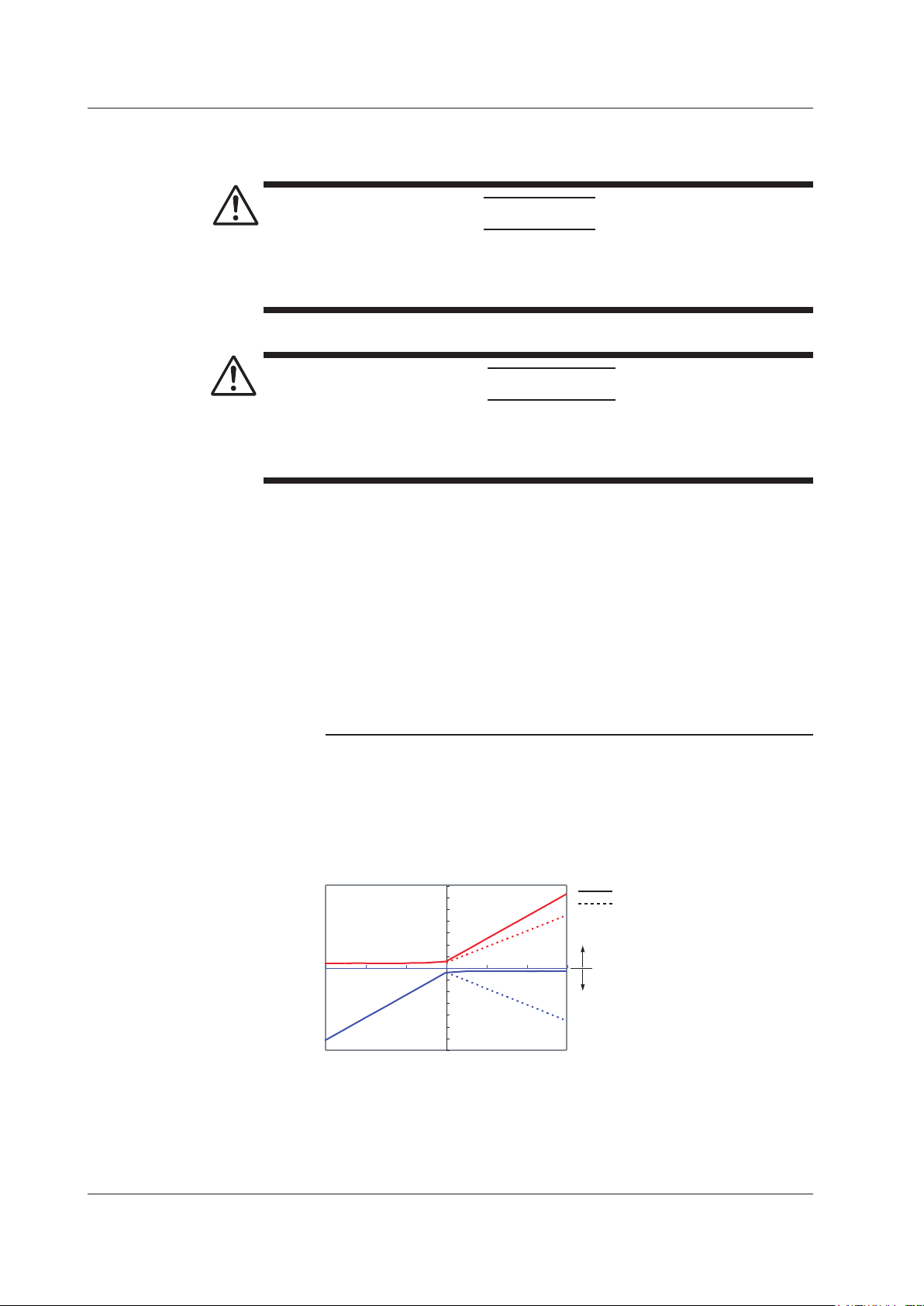
Note
• When using current probes, you may not be able to use a second current probe
simultaneously with the 700938 depending on the value of the curernt being
measured.
• The current consumption of the probe is dependent upon the value of the current
being measured. Do not let the total current consumption of the probe exceed the
rated output current of the 700938. See the examples below.
701930
Current consumption (mA)
Value of the current being measured (A)
DC
AC (f=50Hz)
Positive current
Negative current
-700
-600
-500
-400
-300
-200
-100
0
100
200
300
400
500
600
700
-300 -200 -100 0 100 200
300
Continued on next page

11
IM 700938-01E
701933
-500
-500
-400
-400
-300
-300
-200
-200 -100
00
100
200
200
300
300
400
400
500
500
600
600 700
-600
-600-700 100
100
Figure 1 Current consumption* vs. current to be measured (typical)
*Total of positive and negative power
Current consumption (mA)
Value of the current being measured (A)
Positive current
Negative current
DC
AC (f=50Hz)
Current consumption (mA)
Value of the current being measured (A)
Positive current
Negative current
701932
DC
AC (f=50Hz)
-600
-500
-400
-300
-200
-100
0
100
200
300
400
500
600
0
-50 -40 -30 -20 -10 10 20 30 40 50
701931
Current consumption (mA)
Value of the current being measured (A)
DC
AC (f=50Hz)
Positive current
Negative current
-600
-500
-400
-300
-200
-100
0
100
200
300
400
500
600
-700-600-500-400-300-200
-100 0 100 200 300 400 500 600 700
Fuse Replacement
If the fuse blows, replace it as shown in Figure.
WARNING
• In order to prevent electric shock, always disconnect the power cord
from the connector before replacing the fuse.
• Always replace the fuse with a new fuse of the specified rating.
Never use a fuse of other than the specified rating, and never short
circuit the fuse holder to prevent an accident resulting in injury or death.
100 V, 120 V: F1.0 AL/250 V 20 mm x 5 mm dia.
220 V, 240 V: F0.5 AL/250 V 20 mm x 5 mm dia.
Measurement Procedure

12 IM700938-01E
French
AVERTISSEMENT
• Afin d’éviter tout risque de choc électrique, il faut toujours débrancher le
cordon d’alimentation de la prise avant de remplacer le fusible.
• Toujours remplacer le fusible par un nouveau fusible à la valeur
spécifiée.
Ne jamais utiliser un fusible d’un autre calibre que celui spécifié, et, ne
pas court-circuiter le porte-fusible, pour éviter un accident entraînant
des blessures graves voire mortelles.
100 V, 120 V: F1.0 AL/250 V 20 mm x 5 mm dia.
220 V, 240 V: F0.5 AL/250 V 20 mm x 5 mm dia.
Replace the power fuse and change the supply voltage in the following
manner.
1Turn OFF the power switch and unplug the power cord.
2Insert a tool such as a flathead screwdriver into the fuse holder notch in
the power supply inlet, and use it to pry out the fuse holder.
3When Replacing the Power Fuse Replace the power fuse with another
fuse of the specified rating. When Switching the Current Voltage
(1) Remove the voltage selector box from the fuse holder, rotate the box
so that the desired voltage can be seen through the viewing window,
then reinsert it into the fuse holder. Confirm that the desired voltage
setting appears in the viewing window. (The display will be upside
down.)
(2) Replace the power fuse with another fuse of the specified rating.
4Reinsert the fuse holder into the power inlet.
Screwdriver
Fuse holder
AC Inlet
Use a tool such as a
flathead screwdriver to
pry out the fuse holder.
Fuse Replacement

13
IM 700938-01E
When Switching the Current Voltage
220
100
240
120
Voltage
selector box
Fuse holder
Remove the voltage selector box, rotate
it so that the numbers visible through
the viewing window match the line voltage
that you are using, then reinsert the box
into the fuse holder.
Viewing window
When Replacing the Power Fuse
Fuse
Fuse Replacement

14 IM700938-01E
Specifications
Product Specifications
Compatible probes* 700939 FET Probe 701930 Current Probe
701931 Current Probe 701932 Current Probe
701933 Current Probe
Number of power connectors
2
Output voltage ±12 V ±0.5 V
Operating temperature and humidity range
0 to 40°C (32 to 104°F), 80% RH or less (no
condensation)
Storage temperature and humidity range
-10 to 50°C (14 to 122°F), 80% RH or less (no
condensation)
Location for use Indoor, altitude up to 2000 m (6562 feet)
Rated output current 600 mA (the total value of both outputs)
Rated supply voltage 100 V AC (120, 220, and 240 V requires specification)
(Voltage fluctuation of 10% from the rated supply
voltage are taken into account.)
Ripple supply voltage 3 mVp-p (at the rated output current)
Rated supply frequency 50/60 Hz
Maximum rated power 60 VA (at the rated output current)
External dimensions Approx. 73(W) × 110(H) × 186(D) mm
Approx. 2.87”(W) × 4.33”(H) × 7.32”(D)
Mass Approx. 1.1 kg
Approx. 38.8 oz.
Standard Accessories Power cord (If the suffix code is -Y, a power cord is
not included.), Instruction manual,
Spare fuse
100 V, 120 V : F1.0 AL/250 V, 20 mm × 5 mm dia.
220 V, 240 V : F0.5 AL/250 V, 20 mm × 5 mm dia.
* For the latest information, contact your nearest YOKOGAWA
representatives.
Compliant Standards
Safety standards EN61010-1
Pollution Degree 2
EMC standards Emission EN61326-1 Class B
EN55011 Class B, Group 1
EN6100-3-2 Class B
EN6100-3-3
EMC standards of Australia and New Zealand
EN55011 Class B, Group 1
Immunity EN61326-1 Table 1 (Basic immunity requirement)
Environmental standards EU RoHS Directive compliant
Corrective Action to be Taken in the case of an Abnormality
• If an message appears on the screen, refer to the following pages.
• If maintenance service is required, or if the instrument still does not operate
properly even if the proper corrective action has been taken, contact your
nearest YOKOGAWA representatives, listed on the back cover of this manual.
Symptom Possible Cause Corrective Action
The power cannot be turned ON. The fuse is blown. Replace the fuse.
Other manuals for 700938
1
Table of contents
Other YOKOGAWA Power Supply manuals


