YOKOGAWA GS200 User manual

IM GS210-01EN
3rd Edition
DC Voltage/Current Source
GS200

Product Registration
Thank you for purchasing YOKOGAWA products.
YOKOGAWA provides registered users with a variety of information and
services.
Please allow us to serve you best by completing the product registration
form accessible from our homepage.
http://tmi.yokogawa.com/
PIM 103-03E

Thank you for purchasing the GS200 DC voltage/current source.
This user’s manual explains the features, operating procedures, and handling
precautions of the GS200. To ensure correct use, please read this manual thoroughly
before beginning operation. Keep this manual in a safe place for quick reference in the
event a question arises.
Notes
• The contents of this manual are subject to change without prior notice as a result
of continuing improvements to the instrument’s performance and functionality. The
figures given in this manual may differ from those that actually appear on your screen.
•Every effort has been made in the preparation of this manual to ensure the accuracy
of its contents. However, should you have any questions or find any errors, please
contact your nearest YOKOGAWA dealer.
• Copying or reproducing all or any part of the contents of this manual without
YOKOGAWA’s permission is strictly prohibited.
• The TCP/IP software of this product and the document concerning the TCP/IP
software have been developed/created by YOKOGAWA based on the BSD Networking
Software, Release 1 that has been licensed from University of California.
Trademarks
• Microsoft, Internet Explorer, MS-DOS, Windows, and Windows XP are either
registered trademarks or trademarks of Microsoft Corporation in the United States
and/or other countries.
•Adobe and Acrobat are trademarks of Adobe Systems Incorporated.
• In this manual, the TM and ® symbols do not accompany their respective registered
trademark or trademark names.
• Other company and product names are registered trademarks or trademarks of their
respective holders.
Revisions
• 1st Edition : December 2009
• 2nd Edition: July 2012
• 3rd Edition: September 2013
3rd Edition: September 2013 (YMI)
All Rights Reserved, Copyright ©2009, Yokogawa Electric Corporation
All Rights Reserved, Copyright ©2012, Yokogawa Meters & Instruments Corporation
i
IM GS210-01EN

Checking the Contents of the Package
After receiving the product and opening the package, check the items described below.
If the wrong items have been delivered, if items are missing, or if there is a problem with
the appearance of the items, contact your nearest YOKOGAWA dealer.
GS200
Check that the model name and suffix code given on the name plate on the side panel
are the same as those on your order.
MODEL
SUFFIX
Madein Japan
NO
MODEL
SUFFIX
Made in Japan
NO
MODEL and SUFFIX Codes
Model Suffix Code Description
GS210 DC voltage/current source (front panel output terminals)
GS211 DC voltage/current source (rear panel output terminals)
Supply voltage -1 100 VAC, 50/60 Hz
-4 120 VAC, 50/60 Hz
-7 230 VAC, 50/60 Hz
Power cord1 -D UL/CSA Standard Power Cord (Part No.: A1006WD)
[Maximum rated voltage: 125 V; Maximum rated current: 7A]
-F VDE Standard Power Cord (Part No.: A1009WD)
[Maximum rated voltage: 250 V; Maximum rated current: 10 A]
-Q BS Standard Power Cord (Part No.: A1054WD)
[Maximum rated voltage: 250 V; Maximum rated current: 10 A]
-R AS Standard Power Cord (Part No.: A1024WD)
[Maximum rated voltage: 250 V; Maximum rated current: 10 A]
-H GB Standard Power Cord (Part No.: A1064WD)
[Maximum rated voltage: 250 V; Maximum rated current: 10 A]
Options /MON Voltage and current monitoring
/C10 Ethernet interface
1 Make sure that the attached power cord meets the designated standards of the country and
area that you are using it in.
NO. (Instrument Number)
When contacting the dealer from which you purchased the instrument, please tell them
the instrument number.
ii IM GS210-01EN
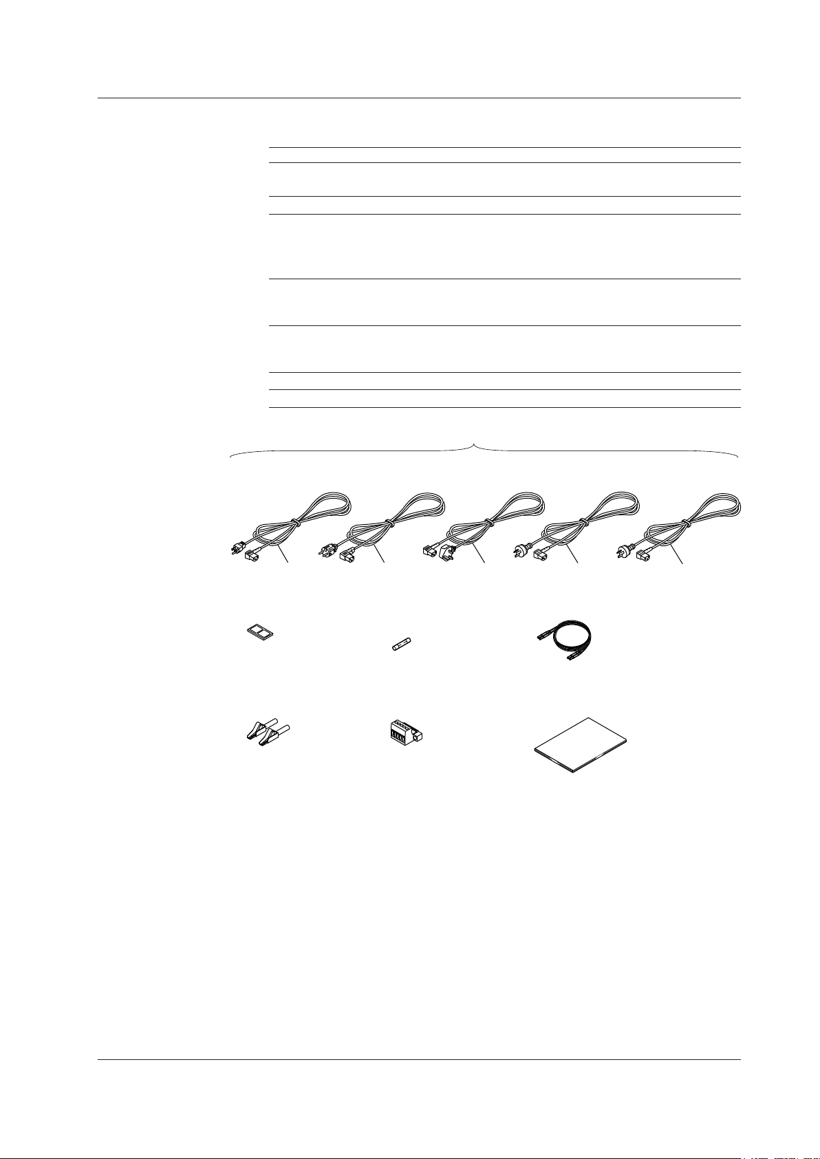
Checking the Contents of the Package
Standard Accessories
The standard accessories below are supplied with the instrument.
Name Model or Part No. Quantity Note
Power cord1See the previous 1
page
Rubber feet A9088ZM 1 Two rubber feet in one set.
Spare power supply fuse
Power cord suffix code
-1 or -4 A1109EF 1 250 V, 1 A, time lag.
-7 A1108EF 1 250 V, 0.5 A, time lag.
Measurement lead 758933 1 set Safety terminal cable. Red and black, 1
pc each.
Only included with the GS210.
Alligator clip adapter 758922 1 set Safety terminal-to-alligator clip adapter.
Red and black, 1 pc each.
Only included with the GS210.
Terminal plug A2006JT 1 Only included with the GS211.
User’s manual IMGS210-01EN 1 This manual.
Rubber feet
A9088ZM
User’s manual (this manual)
IMGS210-01EN
Measurement lead2
758933
Alligator clip adaptor set2
758922
Spare power supply fuse
A1109EF or A1108EF
Terminal plug3
A2006JT
UL, CSA Standard
A1006WD
VDE Standard
A1009WD
BS Standard
A1054WD
AS Standard
A1024WD
DFR
Q
One of these power cords1is supplied according to the suffix code.
H
GB Standard
A1064WD
1 Make sure that the attached power cord meets the designated standards of the country and
area that you are using it in.
2 Only included with the GS210.
3 Only included with the GS211.
iii
IM GS210-01EN

Checking the Contents of the Package
Optional Accessories (Sold separately)
The optional accessories below are available for purchase separately.
Name Model or Minimum Note
Part No. Q’ty.
Measurement lead 758933 1 Safety terminal cable. Length: 1 m.
Red and black, 1 pc. each.
Measurement lead 758917 1 Safety terminal cable. Length: 0.75 m.
Red and black, 1 pc. each.
Banana plug set 758919 1 set φ4 mm plug/φ4 mm socket adapter. Red
and black, 1 pc. each.
Small alligator clip adapter 758922 1 set Safety terminal-to-alligator clip adapter.
Red and black, 1 pc each.
Large alligator clip adapter 758929 1 set Safety terminal-to-alligator clip adapter.
Red and black, 1 pc each.
Fork terminal adapter 758921 1 set Safety terminal-to-fork terminal adapter.
Red and black, 1 pc each.
Conversion adapter 758924 1 BNC-to-safety terminal adapter.
Conversion adapter 751512 1 Banana plug-to-binding post adapter.
BNC cable 366924 1 BNC-BNC, length: 1 m.
BNC cable 366925 1 BNC-BNC, length: 2 m.
Safety terminal adapter 758923 1 set Spring clamp type. Red and black, 1
pc. each.
Safety terminal adapter 758931 1 set Screw-in type. Red and black, 1 pc.
each.
Terminal plug A2006JT 1 For use with the GS211 rear panel
terminals.
Synchronous operation cable 758960 1 RJ-11 cable, 6 pins, length: 1 m.
iv IM GS210-01EN
Safety Precautions
This instrument is an IEC safety class I instrument (provided with a terminal for protective
earth grounding).
The general safety precautions described herein must be observed during all phases
of operation. If the instrument is used in a manner not specified in this manual, the
protection provided by the instrument may be impaired. Yokogawa Electric Corporation
assumes no liability for the customer’s failure to comply with these requirements.
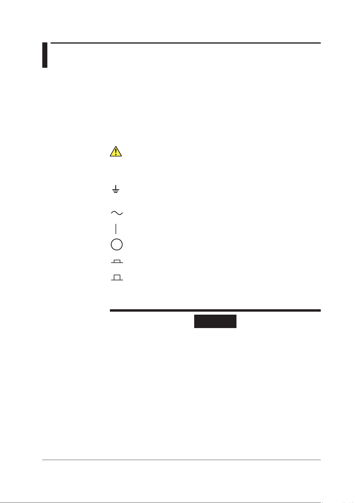
The following symbols are used on this instrument.
Warning: handle with care. Refer to the user’s manual or service manual.
This symbol appears on dangerous locations on the instrument which require
special instructions for proper handling or use. The same symbol appears in the
corresponding place in the manual to identify those instructions.
Ground (earth) or functional ground terminal (do not use this terminal as a
protective ground terminal).
Alternating current
ON (power)
OFF (power)
In-position of a bi-stable push control
Out-position of a bi-stable push control
Be sure to comply with the precautions below. Not complying might result in
injury or death.
WARNING
Use the Instrument Only for Its Intended Purpose
The GS200 is a generator that can generate DC voltage and current. Do not use
this instrument for anything other than as a DC voltage and current generator.
Check the Physical Appearance
Do not use the instrument if there is a problem with its physical appearance.
Use the Correct Power Supply
Before connecting the power cord, ensure that the source voltage matches the
rated supply voltage of the instrument and that it is within the maximum rated
voltage of the provided power cord.
Use the Correct Power Cord and Plug
To prevent the possibility of electric shock or fire, be sure to use the power cord
supplied by YOKOGAWA. The main power plug must be plugged into an outlet with
a protective earth terminal. Do not disable this protection by using an extension
cord without protective earth grounding. Additionally, do not use the power cord
supplied with this instrument with another instrument.
v
IM GS210-01EN

Safety Precautions
Do not use the power cord in a bundled condition. If you use a power plug with
foreign substance on it, insulation may be compromised by humidity or other
factors and may cause a fire. Clean the power plug regularly.
Connect the Protective Grounding Terminal
Be sure to connect the protective earth to prevent electric shock before turning ON
the power. The power cord that comes with the instrument is a three-prong type
power cord. Connect the power cord to a properly grounded three-prong outlet.
Do Not Impair the Protective Grounding
Never cut off the internal or external protective earth wire or disconnect the wiring
of the protective earth terminal. Doing so poses a potential shock hazard.
Do Not Operate with Defective Protective Grounding or Fuse
Do not operate the instrument if the protective earth or fuse might be defective.
Also, make sure to check them before operation.
Do Not Operate in an Explosive Atmosphere
Do not operate the instrument in the presence of flammable gasses or vapors.
Operation in such an environment constitutes a safety hazard.
Do Not Remove the Covers or Disassemble or Alter the Instrument
Only qualified YOKOGAWA personnel may remove the covers and disassemble or
alter the instrument. The inside of the instrument is dangerous because parts of it
have high voltages.
Ground the Instrument before Making External Connections
Securely connect the protective grounding before connecting to the item under
measurement or to an external control unit.
If you are going to touch the circuit, make sure to turn OFF the circuit and check
that no voltage is present.
Measurement Category
The measurement category of the GS200 signal input terminals is Other (O). Do
not use it to measure the main power supply or for Measurement Categories II, III,
and IV.
Installation Location
•This instrument is designed to be used indoors. Do not install or use it outdoors.
•Install the instrument so that you can immediately remove the power cord if an
abnormal or dangerous condition occurs.
CAUTION
Operating Environment Limitations
This product is a Class A (for industrial environment) product. Operation of this
product in a residential area may cause radio interference in which case the user is
required to correct the interference.
vi IM GS210-01EN

Waste Electrical and Electronic Equipment
Waste Electrical and Electronic Equipment (WEEE), Directive 2002/96/EC
(This directive is valid only in the EU.)
This product complies with the WEEE Directive (2002/96/EC) marking
requirement. This marking indicates that you must not discard this electrical/
electronic product in domestic household waste.
Product Category
With reference to the equipment types in the WEEE directive Annex 1, this
product is classified as a “Monitoring and Control instrumentation” product.
Do not dispose in domestic household waste. When disposing products in the EU,
contact your local Yokogawa Europe B. V. office.
New EU Battery Directive
New EU Battery Directive, DIRECTIVE 2006/66/EC
(This directive is valid only in the EU.)
Batteries are included in this product. This marking indicates they shall be sorted
out and collected as ordained in ANNEX II in DIRECTIVE 2006/66/EC.
Battery type
Lithium battery
You cannot replace batteries by yourself. When you need to replace batteries,
contact your local Yokogawa Europe B.V.office.
vii
IM GS210-01EN
Symbols and Notations Used in This Manual
Safety Markings
The following markings are used in this manual.
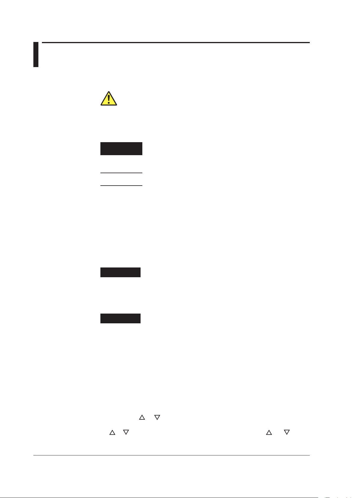
Improper handling or use can lead to injury to the user or damage
to the instrument. This symbol appears on the instrument to indicate
that the user must refer to the user’s manual for special instructions.
The same symbol appears in the corresponding place in the user’
s manual to identify those instructions. In the manual, the symbol is
used in conjunction with the word “WARNING” or “CAUTION.”
WARNING Calls attention to actions or conditions that could cause serious or
fatal injury to the user, and precautions that can be taken to prevent
such occurrences.
CAUTION Calls attention to actions or conditions that could cause light injury to
the user or damage to the instrument or user’s data, and precautions
that can be taken to prevent such occurrences.
Note Calls attention to information that is important for proper operation of
the instrument.
Notations Used in the Procedural Explanations
On pages that describe the operating procedures in chapters 3 through 15 and the
appendix, the following symbols are used to distinguish the procedures from their
explanations.
Procedure Carry out the procedure according to the step numbers. All
procedures are written under the assumption that you are starting
operation at the beginning of the procedure, so you may not need
to carry out all the steps in a procedure when you are changing the
settings.
Explanation This section describes the setup items and the limitations regarding
the procedures. It may not give a detailed explanation of the feature.
For a detailed explanation of the feature, see chapter 2.
<<Corresponding Command Mnemonic>>
Indicates a communication command that corresponds to the feature described on the
procedural explanation page.
Characters and Terminology Used in Procedural Explanations
Keys
Bold characters used in the procedural explanations indicate characters that are marked
on the panel keys.
NUM LOCK + or
This means the following: press the NUM LOCK key to make it illuminate, and then press
the or key. When the instrument is in this state, you can use the and keys to
directly access the items that are marked above and below these keys (numbers 0 to 9,
period, and BS).
viii IM GS210-01EN

Contents
Checking the Contents of the Package.............................................................................................ii
Safety Precautions............................................................................................................................v
Waste Electrical and Electronic Equipment .................................................................................... vii
New EU Battery Directive ............................................................................................................... vii
Symbols and Notations Used in This Manual ................................................................................ viii
Chapter 1 Component Names and Functions
1.1 Front Panel....................................................................................................................... 1-1
1.2 Rear Panel ....................................................................................................................... 1-2
1.3 Display Mode and Displayed Contents ............................................................................ 1-3
1.4 Keys ................................................................................................................................. 1-5
Chapter 2 Features
2.1 SystemConguration ....................................................................................................... 2-1
ProductFeaturesandSystemConguration ................................................................ 2-1
2.2 Source Feature and Measurement Feature (Monitoring feature; /MON option)............... 2-3
2.3 Source .............................................................................................................................. 2-6
Source Range ............................................................................................................... 2-6
Source Function............................................................................................................ 2-7
Source Action................................................................................................................ 2-7
Output ON/OFF............................................................................................................. 2-8
DUT Protection Using Limiters...................................................................................... 2-8
Local Sense and Remote Sense .................................................................................. 2-9
Guard Terminal Feature .............................................................................................. 2-10
2.4 Programs.........................................................................................................................2-11
Program Feature..........................................................................................................2-11
Program Interval Time..................................................................................................2-11
Program Slope Time ....................................................................................................2-11
Repeating Programs ................................................................................................... 2-12
Program Triggers ........................................................................................................ 2-12
Program Files.............................................................................................................. 2-13
Executing Programs.................................................................................................... 2-14
2.5 Measurement (Monitoring feature; /MON option)........................................................... 2-16
Measurement Function and Measurement Range...................................................... 2-16
Measurement ON/OFF ............................................................................................... 2-16
Measurement Operation ............................................................................................. 2-16
Measurement Delay.................................................................................................... 2-17
Highly Accurate Measurement and High-Speed Measurement .................................. 2-17
NULL Computation...................................................................................................... 2-17
Store/Recall (Statistical Computation Value Display).................................................. 2-18
2.6 Triggering ....................................................................................................................... 2-20
Overview ..................................................................................................................... 2-20
Program Triggers ........................................................................................................ 2-20
Measurement Triggers (/MON option) ........................................................................ 2-21
Trigger Block Diagram ................................................................................................ 2-22
Trigger Output ............................................................................................................. 2-23
Trigger Hold ................................................................................................................ 2-23
Sampling Error ............................................................................................................ 2-23
3
2
1
4
5
6
7
8
9
10
11
12
13
14
15
App
Index
ix
IM GS210-01EN

2.7 Synchronization.............................................................................................................. 2-24
Synchronization .......................................................................................................... 2-24
External I/O ................................................................................................................. 2-24
2.8 Other Features ............................................................................................................... 2-25
USB Storage Feature.................................................................................................. 2-25
USB Communication (USB-TMC command control) .................................................. 2-26
Ethernet Communications (/C10 option)..................................................................... 2-27
GP-IB Communications .............................................................................................. 2-27
Saving, Loading, and Deleting Setup Data ................................................................. 2-27
Selecting the Settings Applied at Power-On ............................................................... 2-27
Chapter 3 Instrument Preparation and Common Operations
3.1 Handling Precautions ....................................................................................................... 3-1
3.2 Installation ........................................................................................................................ 3-3
3.3 Connecting the Power Supply .......................................................................................... 3-6
3.4 Turning the Power Switch On and Off.............................................................................. 3-7
3.5 Wiring Precautions ........................................................................................................... 3-8
3.6 Wiring the GS211 Rear Panel Terminal Plug.................................................................... 3-9
3.7 Setting the Date, Time, and the Time Difference from GMT (Greenwich Mean Time) ... 3-10
Chapter 4 Common Settings
4.1 Basic Key Operations and How to Enter Values .............................................................. 4-1
4.2 Selecting the Wiring System (Remote Sense or Local Sense) ........................................ 4-3
4.3 Setting the Guard Terminal............................................................................................... 4-5
4.4 USB Storage Feature ....................................................................................................... 4-7
Chapter 5 Source
5.1 Setting the Source Function ............................................................................................. 5-1
5.2 Setting the Source Range ................................................................................................ 5-2
5.3 Setting the Source Level .................................................................................................. 5-3
5.4 Setting the Limiter ............................................................................................................ 5-4
5.5 Turning the Output On and Off......................................................................................... 5-5
Chapter 6 Programs
6.1 Turning Program Repetition Mode On and Off................................................................. 6-1
6.2 Setting the Program Interval Time.................................................................................... 6-2
6.3 Setting the Program Slope Time ...................................................................................... 6-3
6.4 Setting the Program Trigger (/MON option)...................................................................... 6-4
6.5 Creating and Editing Programs ........................................................................................ 6-5
6.6 Saving and Loading Programs ......................................................................................... 6-8
6.7 Executing Programs ....................................................................................................... 6-12
Chapter 7 Measurement (Option)
7.1 Turning Measurement On and Off.................................................................................... 7-1
7.2 Setting the Integration Time ............................................................................................. 7-2
7.3 Setting the Measurement Delay ....................................................................................... 7-3
7.4 Selecting the Measurement Trigger ................................................................................. 7-4
7.5 Setting the Measurement Timer ....................................................................................... 7-5
7.6 Turning the NULL Computation On and Off ..................................................................... 7-6
7.7 Zero Calibration (Zero reference measurement).............................................................. 7-7
7.8 Storing Measured Results ................................................................................................ 7-8
7.9 Performing Statistical Computations on Measured Values (Recall) ............................... 7-10
Contents
xIM GS210-01EN

Contents
Chapter 8 Synchronous Operation
8.1 Synchronous Operation Using the BNC I/O Terminals (IN and OUT) .............................. 8-1
8.2 Using the RJ-11 Connectors (SYNC IN and SYNC OUT) to Perform Synchronous
Operation.......................................................................................................................... 8-4
Chapter 9 Other Features
9.1 Initializing Setup Data....................................................................................................... 9-1
9.2 Saving, Loading, and Deleting Setup Data ...................................................................... 9-2
9.3 Selecting the Settings Applied at Power-On..................................................................... 9-4
9.4 Selecting the Display Brightness, Turning the Display Off, and Turning the Beep
Sound On and Off............................................................................................................. 9-5
9.5 Selecting the CSV File Format ......................................................................................... 9-6
9.6 Error Log Display.............................................................................................................. 9-7
Chapter 10 USB Interface
10.1 USBInterfaceFeaturesandSpecications.................................................................... 10-1
10.2 Setting the USB Interface Mode..................................................................................... 10-2
10.3 Viewing the VISA Setup Information............................................................................... 10-3
Chapter 11 Ethernet Interface (Option)
11.1 EthernetInterfaceFeaturesandSpecications ..............................................................11-1
11.2 Connecting to a Network .................................................................................................11-2
11.3 ConguringNetworkSettings(TCP/IP)...........................................................................11-3
11.4 Viewing the Network Settings..........................................................................................11-6
11.5 Web Server Feature ........................................................................................................11-7
Chapter 12 GP-IB Interface
12.1 GP-IBInterfaceFeaturesandSpecications ................................................................. 12-1
12.2 Connecting the GP-IB Cable .......................................................................................... 12-2
12.3 Setting the GP-IB Address and Command Mode........................................................... 12-3
12.4 7651-Compatible Mode .................................................................................................. 12-4
12.5 Responses to Interface Messages ................................................................................. 12-5
12.6 About the IEEE 488.2-1992 Standard ............................................................................ 12-7
Chapter 13 Communication Commands
13.1 Program Format ............................................................................................................. 13-1
13.1.1 Symbols Used in the Syntax............................................................................ 13-1
13.1.2 Messages ........................................................................................................ 13-1
13.1.3 Commands ...................................................................................................... 13-3
13.1.4 Responses....................................................................................................... 13-5
13.1.5 Data ................................................................................................................. 13-5
13.2 Commands ..................................................................................................................... 13-7
13.2.1 List of Commands............................................................................................ 13-7
13.2.2 Output Commands (OUTPut group).............................................................. 13-10
13.2.3 Source Commands (SOURce group) .............................................................13-11
13.2.4 Program Commands (PROGram group) ....................................................... 13-13
13.2.5 Measurement Commands (SENSe group).................................................... 13-15
13.2.6 Measured Value Read Commands (INITiate, FETCh, READ, and MEASure
groups)........................................................................................................... 13-17
13.2.7 Store/Recall Commands (TRACe group) ...................................................... 13-18
13.2.8 External I/O Commands (ROUTe group)....................................................... 13-20
13.2.9 System Commands (SYSTem group)............................................................ 13-21
3
2
1
4
5
6
7
8
9
10
11
12
13
14
15
App
Index
xi
IM GS210-01EN

13.2.10 Status Commands (STATus group) ............................................................... 13-23
13.2.11 Common Commands..................................................................................... 13-24
13.3 Status Reports.............................................................................................................. 13-26
13.3.1 Status Reports............................................................................................... 13-26
13.3.2 Status Byte .................................................................................................... 13-28
13.3.3 Standard Event Register................................................................................ 13-29
13.3.4 Extended Event Register............................................................................... 13-30
13.3.5 Output Queue and Error Queue .................................................................... 13-31
Chapter 14 Troubleshooting and Maintenance
14.1 Troubleshooting.............................................................................................................. 14-1
14.2 Error Code Descriptions and Corrective Actions ............................................................ 14-3
14.3 Self-Test ......................................................................................................................... 14-6
14.4 Viewing the Product Information..................................................................................... 14-8
14.5 Updating the System Firmware ...................................................................................... 14-9
14.6 Changing the Power Fuse.............................................................................................14-11
14.7 Recommended Replacement Parts and Maintenance................................................. 14-12
Chapter 15 Specications
15.1 Source Section ............................................................................................................... 15-1
15.2 Measurement Section (On models with the /MON option) ............................................. 15-3
15.3 Features ......................................................................................................................... 15-3
15.4 External I/O Section (BNC (IN/OUT) and I/O for synchronous operation
(SYNC IN/OUT))............................................................................................................. 15-4
15.5 Interface ......................................................................................................................... 15-5
15.6 GeneralSpecications ................................................................................................... 15-6
15.7 External Dimensions ...................................................................................................... 15-8
Appendix
Appendix 1 Factory Default Settings..................................................................................... App-1
Appendix 2 Block Diagram.................................................................................................... App-2
Index
Contents
xii IM GS210-01EN
3
2
1
4
5
6
7
8
9
10
11
12
13
14
15
App
Index
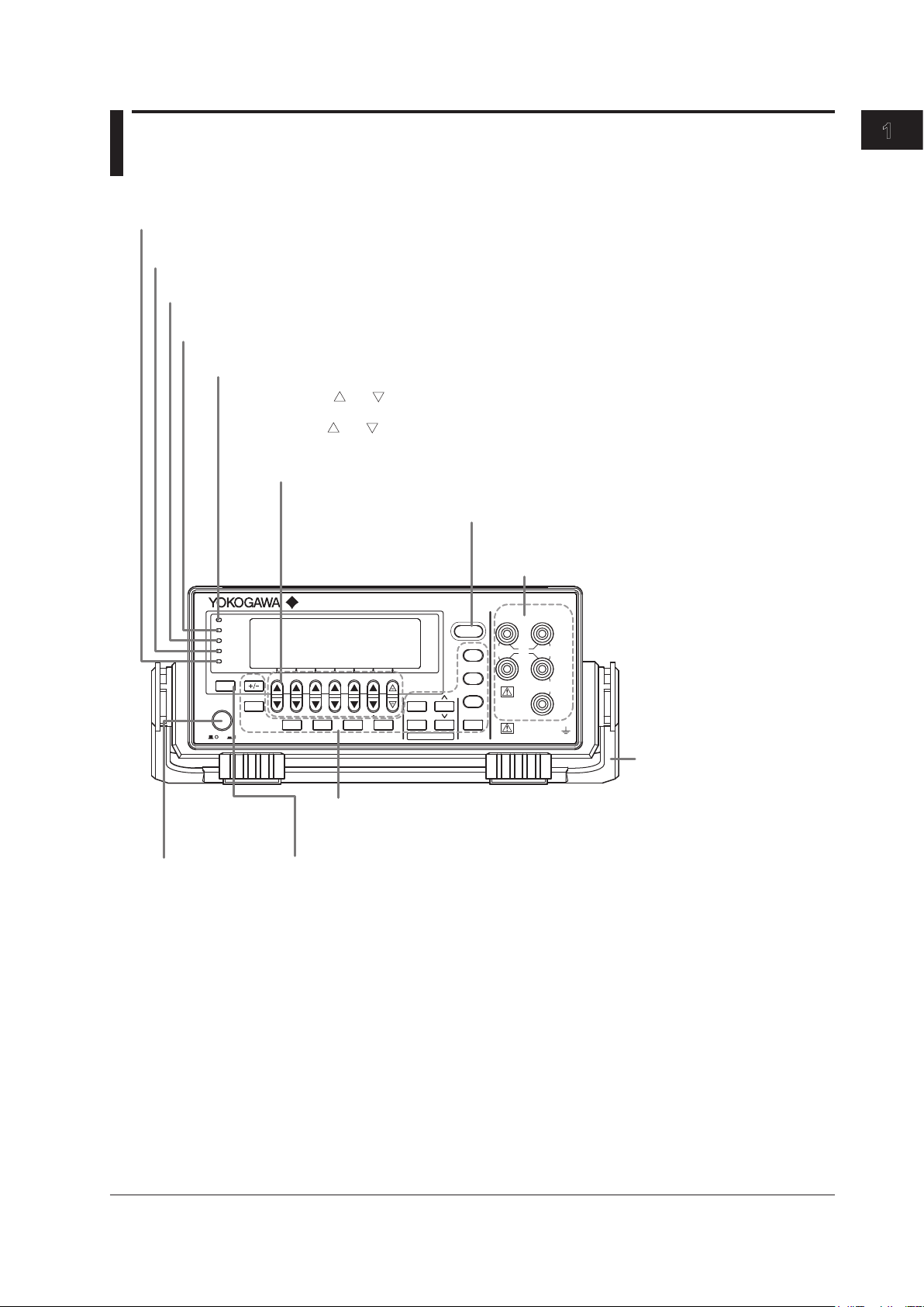
1.1 Front Panel
GS200
DC VOLTAGE/CURRENT SOURCE
SAMPLE
ERROR
REPEAT
STORE
REMOTE
ERROR
LOCAL
ESC
POWER
NUM
LOCK
1 2 3 4 5
BS
RANGE
6 7 8 9 0
UTILITY
SETUP
LIMIT
MEASURE
PROGRAM
END
DEL
HOLD
STEP
RUN
PROGRAM
OUTPUT
V
mV
mA
SRQ
ENTER
SENSE OUTPUT
32V
MAX 0.5V
MAX 32V
200mA MAX
Hi
Lo
42V
10mA
PEAK
G
G TERM 250 V PEAK TO
Power switch
→ Section 3.4
Handle
Used to carry the GS200.
→ Section 3.2
Output terminals (only on the GS210)
Used to connect the included measurement leads.
→ Sections 3.5, 4.2, and 4.3
Soft keys, and
keys, and the keypad
• Use the soft keys to select items on the soft key menus that appear during configuration.
• Use the and keys to increase and decrease each digit of the displayed value during numeric
input.
• Use the keypad to specify a value directly during numeric input.
→ Section 4.1
ESC (LOCAL) key
Switches the display or clears a soft key menu → Section 4.1
Setup and execution keys
These keys are used to change settings or execute operations.
Press a setup key to show the respective setup item. → Sections 1.4 and 4.1
Remote indicator
Illuminates when the GS200 is in remote mode (controlled through communications) → Section 12.1
Store indicator
Illuminates when store mode is turned on → Section 7.8
Sampling error indicator
Illuminates when a sampling error occurs in a program or measurement trigger → Sections 6.4 and 7.4
Repeat indicator
Illuminates when the program’s repeat mode is turned on → Section 6.1
Output control key
Press to turn the source on and off. → Section 5.5
Error indicator
Illuminates when there are errors in the error log → Section 14.2
1-1
IM GS210-01EN
Component Names and Functions
Chapter 1 Component Names and Functions

1.2 Rear Panel
LINK ACT
ETHERNET
100BASE-TX
IN
OUT USB
SYNC
IN OUT
100V AC
80 VA MAX
50/60 Hz
FUSE 250 V T 1A
GP-IB (IEEE 488)
Cooling fan → Section 3.2
USB port
Used to connect the GS200 to a PC that has a USB interface and to access the GS200
as USB storage or to control the GS200 through USB-TMC commands.
→ Sections 4.4 and 10.2
I/O terminals for synchronous operation
Used to connect multiple GS200s and perform synchronous operation. → Section 8.2
Ethernet port
Used to connect the GS200 to a network. → Section 11.2
BNC I/O terminals
Used to receive and transmit trigger, output state, and source
change completion signals. → Section 8.1
Power inlet
Connects to a power supply → Section 3.3
GP-IB connector
Used when controlling the GS200 with commands
through the GP-IB interface. → Section 12.2
Output terminal (only on the GS211)
Used to connect the DUT cable. → Sections 3.5, 3.6, 4.2, and 4.3
*
* Only on models with the Ethernet option (/C10).
1-2 IM GS210-01EN
3
2
1
4
5
6
7
8
9
10
11
12
13
14
15
App
Index
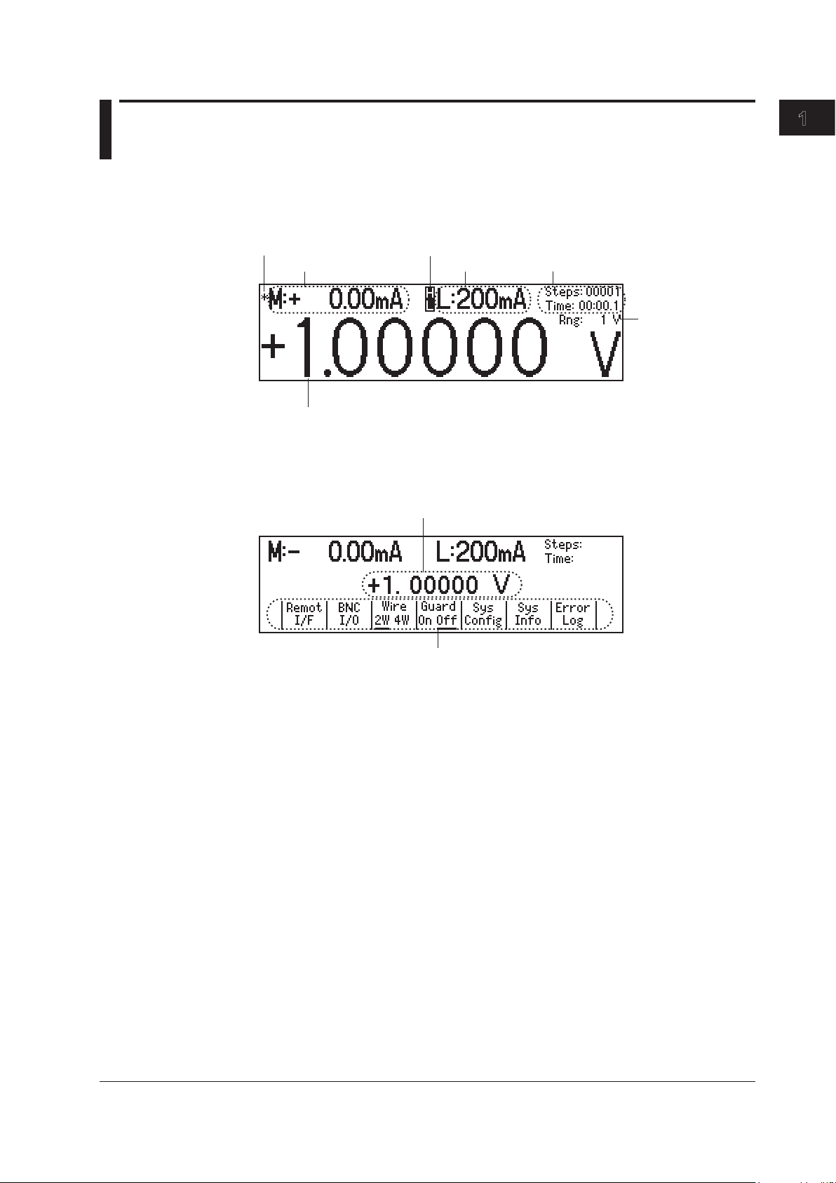
1.3 Display Mode and Displayed Contents
Display Mode
Main Screen
Limiter indicators
H: High limiter
L: Low limiter
Limit
Measured value1
Source level
Source range
Program execution status
Measurement sample
indicator1
1 This is displayed on models with the monitoring (/MON) option.
Menu Screen
Source level
Menu items
Displayed Contents
Source Level
The source level that is being produced is displayed here.
Measurement Sample Indicator (On models with the /MON option)
During measurement, an asterisk illuminates. When the measurement completes, the
asterisk turns off. If you are performing sequential measurements that have a short
integration time, the asterisk illuminates and turns off once every 100 ms.
Measured Value (On models with the /MON option)
When the source function is set to voltage, this displays the measured current. When the
source function is set to current, this displays the measured voltage. When there is no
measured value, “-------” is displayed. When the source range is set to 10 mV or 100 mV,
you cannot use the measurement (monitoring) feature. In these situations, the message
“Cannot measure in mV source range” is displayed. When the measurement feature is
turned off, “Off” is displayed.
On models without the monitoring (/MON) option, nothing is displayed in the measured
value area.
1-3
IM GS210-01EN
Component Names and Functions

Limits
When the source function is set to voltage, this displays the current limit. When the
source function is set to current, this displays the voltage limit. When the source range
is set to 10 mV or 100 mV, the limit is fixed to 200 mA (you cannot change this value). In
these situations, “------mA” is displayed for the limit.
Note
In voltage source mode’s 10 mV and 100 mV ranges, the output resistance is approximately 2
Ω. Therefore, these ranges are not suitable when the GS200 is connected to a load that allows
current to flow (a low-impedance load). Connect a load that allows as little current to flow as
possible (a high-impedance load).
Limiter Indicators
• is displayed when the high limiter is activated.
• is displayed when the low limiter is activated.
Program Execution Status
When a program is running, the following items are displayed.
•Steps: The step number that is currently being executed.
• Time: The remaining interval time (minutes:seconds.tenths of seconds).
Source Range
The source range that is currently in use is displayed here.
1-4 IM GS210-01EN
1.3 Display Mode and Displayed Contents
3
2
1
4
5
6
7
8
9
10
11
12
13
14
15
App
Index
1-5
IM GS210-01EN
Component Names and Functions
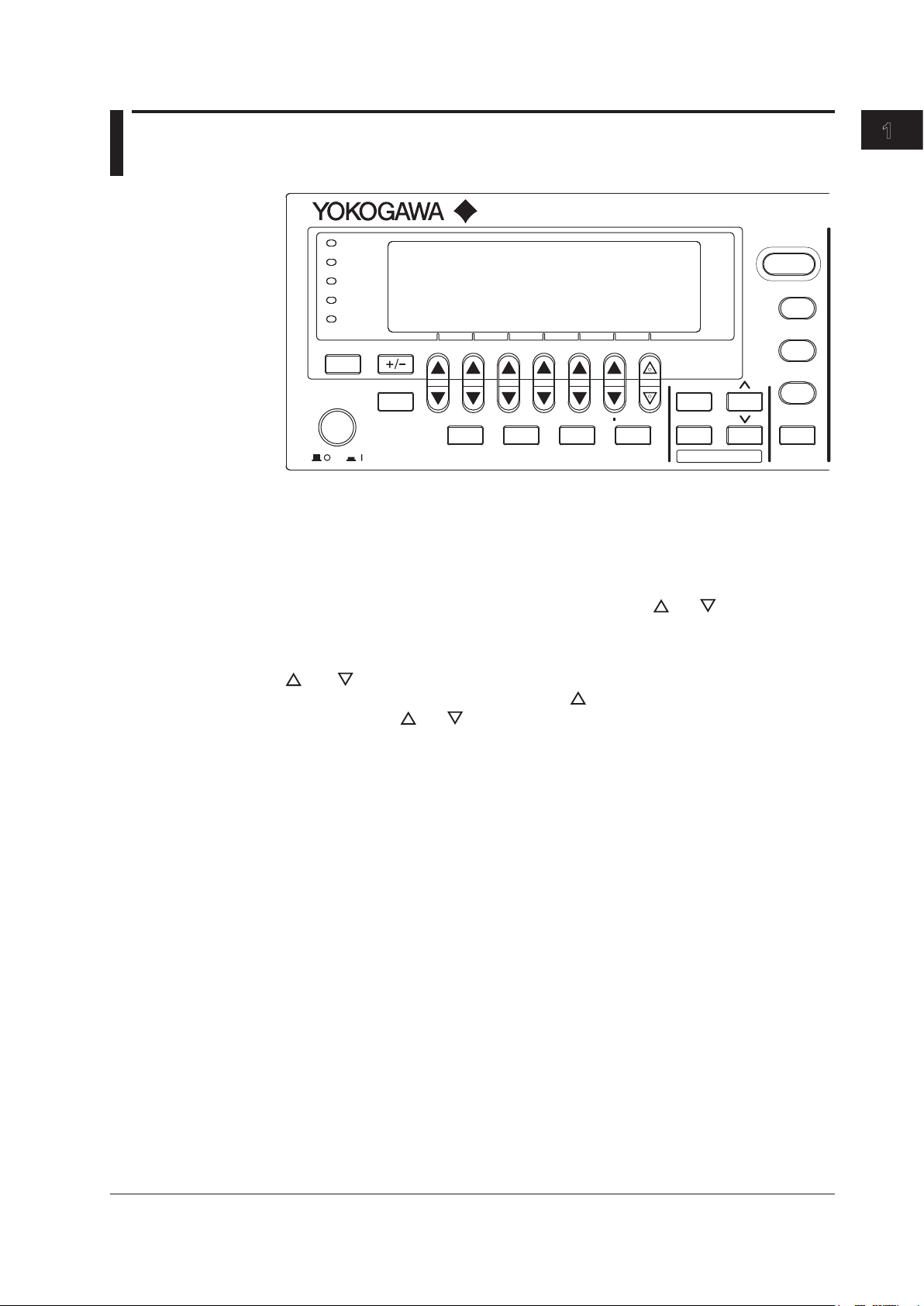
1.4 Keys
GS200
DC VOLTAGE/CURRENT SOURCE
SAMPLE
ERROR
REPEAT
STORE
REMOTE
ERROR
LOCAL
ESC
POWER
NUM
LOCK
1 2 3 4 5
BS
RANGE
6 7 8 9 0
UTILITY
SETUP
LIMIT
MEASURE
PROGRAM
END
DEL
HOLD
STEP
RUN
PROGRAM
OUTPUT
V
mV
mA
SRQ
ENTER
General-Purpose Keys
+/- Key (Section 4.1)
This key is used when you enter numeric values or change a value’s sign.
NUM LOCK Key (Section 4.1)
When you press the NUM LOCK key, the NUM LOCK key’s indicator illuminates, and the
GS200 enters keypad mode. In this mode, you can use the and keys to directly
access the items that are marked above and below these keys (numbers 0 to 9, period,
and BS).
and Keys (Section 4.1)
When a soft key menu is displayed, press the keys to make selections and perform
actions. Press the and keys to enter values in up/down key mode and keypad
mode.
ENTER Key (Section 4.1)
When the GS200 is in keypad mode, press this key to enter the setting that you have
specified.
ESC (LOCAL) Key (Section 4.1)
When a menu is displayed, press this key to display the previous menu (to move up one
level in the menu hierarchy). If you press this key when you are entering a value with
the GS200 in up/down key mode, the GS200 returns to one screen before the numeric
value input screen. When the GS200 is displaying the top menu, you can press this key
to switch between the top menu and the main screen. This is also the LOCAL key. When
the GS200 is in remote mode, you can press this key to return it to local mode.

1-6 IM GS210-01EN
Source Keys
V Key (Sections 5.2 and 5.3)
If you press this key when the GS200 is in up/down key mode and is displaying the main
screen, the source function is set to voltage, and the source range is set to 1 V. If you
press this key when the GS200 is in keypad mode and is displaying the main screen, the
voltage source level that you specified is fixed, the source function is set to voltage, and
the source range is set to the most appropriate range greater than or equal to the 1 V
range.
mV Key (Sections 5.2 and 5.3)
If you press this key when the GS200 is in up/down key mode and is displaying the
main screen, the source function is set to voltage, and the source range is set to 10 mV
(the circuit that produces the 10 mV range uses the voltage divider). If you press this
key when the GS200 is in keypad mode and is displaying the main screen, the voltage
source level that you specified is fixed, the source function is set to voltage, and the
source range is set to the most appropriate range.
mA Key (Sections 5.2 and 5.3)
If you press this key when the GS200 is in upd/down key mode and is displaying the
main screen, the source function is set to current and the source range is set to 1 mA. If
you press this key when the GS200 is in keypad mode and is displaying the main screen,
the current source level that you specified is fixed, the source function is set to current,
and the source range is set to the most appropriate range.
RANGE Keys (Section 5.2)
Press these keys to change the source range. Press the key to increase the source
range by one. Press the key to decrease the source range by one. When a menu is
displayed, you can use the key as a menu selection soft key. You cannot change the
range continuously by holding these keys down.
Depending on the operation menu, these keys may be used to scroll the screen. In these
situations, you can scroll the screen by holding these keys down.
LIMIT Key (Section 5.4)
Press this key to display the limit input screen. If you press this key in keypad mode
when you are entering a limit, the limit that you specified is discarded, and the GS200
returns to the main screen.
OUTPUT Key (Section 5.5)
Output turns on and off each time that you press the OUTPUT key. When output is
turned on, this key illuminates in red. When output is turned off, this key turns off. When
you turn output on, the display switches to the main screen.
1.4 Keys
Table of contents
Other YOKOGAWA Power Supply manuals


