York International YCAA-B Guide

AIR COOLED LIQUID CHILLERS
and HEAT PUMPS
INSTALLATION, CO ISSIONING,
OPERATION AND AINTENANCE
REFRI ERANT TYPE:
R407C YCAA-B
R22 YCAA-H
035B -100 Rev. 409012
(09/03)
GB


TABLE OF CONTENTS
1 SUPPLIER INFOR ATION
1.1 Introduction 1.1
1.2 Warranty 1.1
1.3 Safety 1.1
1.4 Emergency Stops/Shutdown 1.2
1.5 About this Manual 1.2
1.6 Safety Labels 1.3
1.7 Material Safety Data 1.4
2 PRODUCT DESCRIPTION
2.1 Introduction 2.1
2.2 eneral Specification 2.2
2.3 Compressors 2.2
2.4 Refrigerant Circuits 2.2
2.5 Evaporators 2.2
2.6 Air Cooled Condensers 2.2
2.7 Power And Controls 2.3
2.8 Options 2.3
2.9 Nomenclature 2.4
2.10 Theory Of Operation 2.4
3 TRANSPORTATION, HANDLING AND
STORAGE
3.1 Inspection 3.1
3.2 Handling 3.1
3.3 Anchorage 3.2
3.4 Storage 3.2
4 INSTALLATION
4.1 Location 4.1
4.2 Defrost Water Drainage
(YCAA-H Units) 4.1
4.3 Spring Isolator Installation 4.1
4.4 External Water System 4.2
4.5 Water connections 4.3
4.6 Hydro Kit Connection (Option) 4.3
4.7 Electrical Supplies 4.4
4.8 Electrical Connections 4.4
5 CO ISSIONING
5.1 Preliminary Checks 5.1
5.2 Starting 5.1
5.3 Performance Check 5.2
5.4 Customer Handover 5.2
6 OPERATION
6.1 Control Panels 6.1
6.2 Unit Starting 6.2
6.3 Water Temperature Display 6.3
6.4 Operating Mode Change
(YCAA-H units) 6.3
6.5 Alarm Display and Reset 6.3
6.6 Unit Shutdown 6.3
6.7 ISN Control Panel (Standard YCAA
models 170 - 210, optional YCAA
models 60 - 150) 6.4
6.8 Protection and Safety Devices 6.5
(09/03)
035B09012-100 Rev. 4 I
-
i

7 AINTENANCE
7.1 eneral Requirements 7.1
7.2 Daily Maintenance 7.1
7.3 Refrigerant Charge 7.2
7.4 Compressors 7.2
7.5 Condenser Coils 7.2
7.6 Condenser Fans 7.2
7.7 Filter Drier 7.2
7.8 Sight lass 7.2
7.9 Thermostatic Expansion Valve 7.3
7.10 Evaporator 7.3
8 TROUBLE SHOOTING
9 TECHNICAL DATA
9.1 Unit Pressure Drop raphs 9.1
9.2 lycol Data raphs 9.2
9.3 Safety Switch Settings 9.3
9.4 Operational Limits 9.3
9.5 Sound Power Levels
(Frequency Analysis (Spectrum)) 9.5
9.6 Physical Data 9.6
9.7 Unit Electrical Data 9.11
9.8 Dimensions 9.14
9.9 Space Requirements 9.17
9.10 Weight and Isolator Data 9.18
9.11 Spring Isolator Installation 9.20
9.12 Process and Instrumentation
Diagrams 9.21
10 SPARE PARTS
10.1 Recommended Spares 10.1
10.2 Recommended Compressor Oils 10.1
10.3 Associated Diagrams 10.2
11 DE-CO ISSIONING,
DIS ANTLING AND DISPOSAL
11.1 eneral 11.1
(09/03)
I
-
ii 035B09012-100 Rev. 4

1 SUPPLIER INFOR ATION
1.1 Introduction
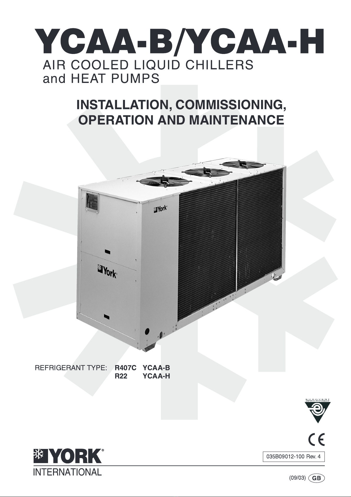
York YCAA Series chillers are manufactured to the most
stringent design and construction standards to ensure
high performance, reliability and adaptability to all types
of air conditioning installations. The unit is intended for
cooling water/ lycol (and heating water in the case of
heat pump units) and is not suitable for purposes other
than those specified in this manual.
The unit can be converted into a total cooling/heating
plant with the field mounted Hydro Kit option.
If the unit is used improperly, or for different purposes
without the prior agreement of York International or their
agents, then such use would be outside the scope and
may be unsafe.
This manual contains all the information required for
correct installation and commissioning of the unit,
together with operation and maintenance instructions.
The manual should be read thoroughly before
attempting to operate or service the unit.
With the exception of the operations detailed in this
manual, all installation, commissioning and
maintenance tasks must be performed by suitably
trained and qualified personnel from an Authorised York
Service Centre.
The manufacturer is not liable for injury or damage
resulting from incorrect installation/commissioning or
operation, insufficient maintenance and/or failure to
follow the procedures and instructions contained in this
manual.
1.2 Warranty
The unit is supplied finished, tested and ready to work.
The unit warranty will be void if any modification to the
unit is carried out without written agreement of York
International.
For warranty purposes, the following conditions must be
satisfied:
n
The initial start of the unit must be carried out by
trained personnel from an Authorised York Service
Centre.
n
Maintenance must be carried out by properly
trained personnel.
n
Only genuine York spare parts must be used.
n
All the scheduled maintenance operations detailed
in this manual must be performed at the specified
times.
A suitable water filter must be installed in the
external water circuit or the warranty will not
be valid. The field mounted Hydro Kit option
includes a water filter as standard.
Failure to satisfy any of these conditions will
automatically void the warranty.
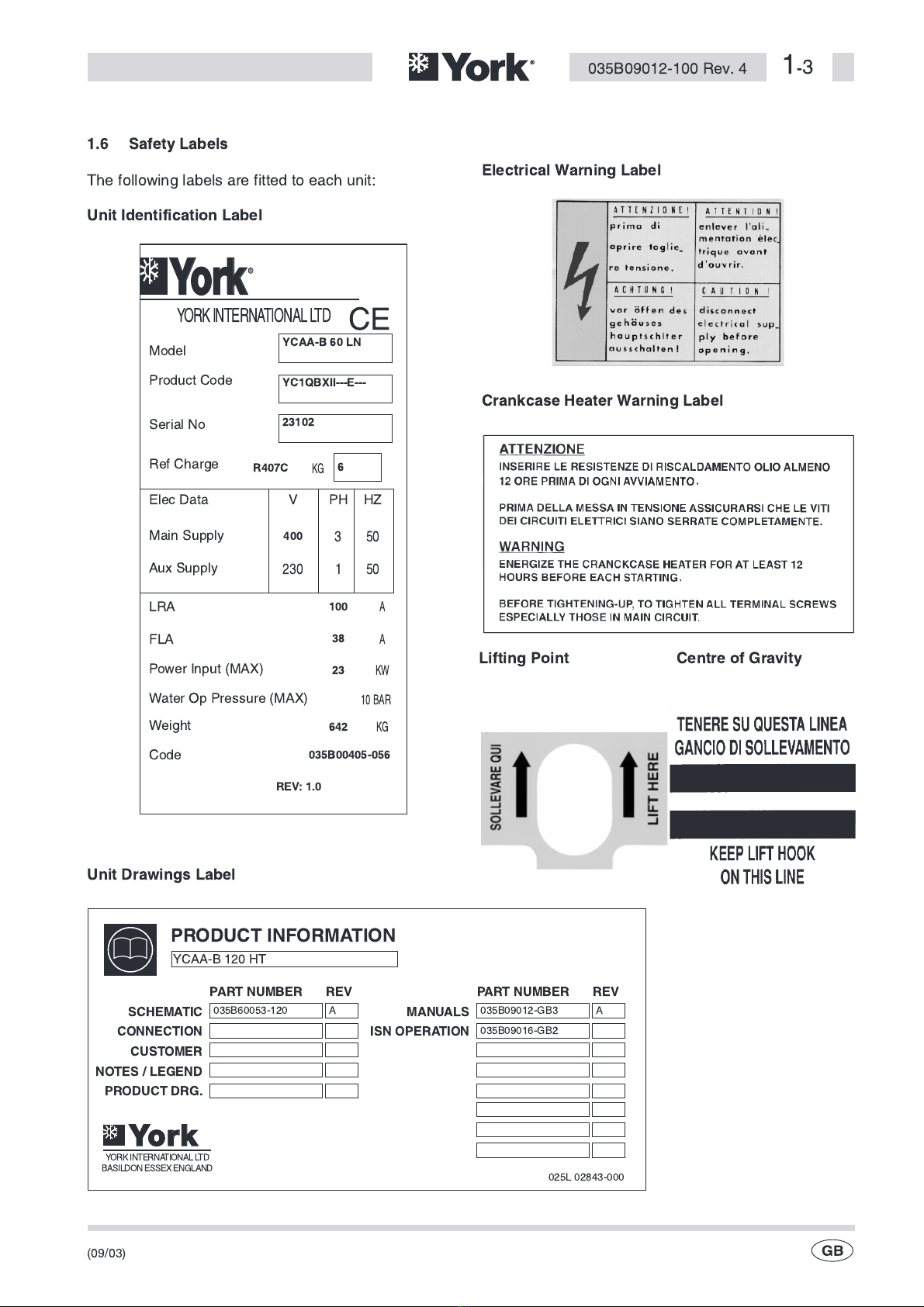
1.3 Safety
Standards for Safety
YCAA Series chillers are designed and built within an
EN ISO 9001 accredited design and manufacturing
organisation and, within the limits specified in this
manual, are in conformity with the essential health and
safety requirements of the following European Union
Directives:
Machinery Directive (89/392/EEC)
Low Voltage Directive (73/23/EEC, EN 60204)
EMC Directive (89/336/EEC)
Refrigeration equipment built at York Basildon conforms
to the applicable and essential safety requirements of
Pressure Equipment Directive 97/23/EC (PED) and
bear CE marking.
Responsibility for Safety
Every care has been taken in the design and
manufacture of the units to ensure that they meet the
safety requirements listed in the previous paragraph.
However, the individual operating or working on any
machinery is primarily responsible for:
Personal safety, safety of other personnel, and the
machinery.
Correct utilisation of the machinery in accordance with
the procedures detailed in the manuals.
(09/03)
035B09012-100 Rev. 4 1
-
1

The unit contains refrigerant vapour and
liquid under pressure within the heat
exchangers, compressors and pipework.
Release of refrigerant can be a danger and
cause injury.
Fan guards must be fitted at all times and
not removed unless the main power
supply has been isolated.
It is the responsibility of the user to ensure
that the unit is suitable for the conditions
of use and that installation and regular
maintenance is carried out by personnel
with the appropriate skills and in
accordance with this manual.
Support of the unit must be provided as
indicated in this manual, failure to provide
proper support may put personnel at risk
of injury.
The unit is not designed to withstand loads or
stresses from adjacent equipment, pipework
and structures. Any such extraneous loads or
stress may cause failure or collapse which
can be a danger and cause injury. In such
cases the warranty will be void.
Do not discard or burn the packaging in the
environment.
1.4 Emergency Stops/Shutdown
The isolator switch on the electrical panel will shutdown
the unit, when set to the 0 (Off) position.
The unit should be restarted in accordance with the
procedure detailed in this manual.
On models 60 - 150 remove the protection
plate on the isolator switch before operating
the unit.
1.5 About this anual
For safety reasons, the instructions contained in this
manual must be followed categorically; furthermore,
damage caused by misuse is not covered by the
warranty.
This manual uses the following conventions:
Warning messages alert you to a specific
procedure or practice which, if not
followed correctly, could cause serious
personal injury.
Caution messages appear before procedures
which, if not observed, could result in damage
to the unit.
Notes contain particularly important
comments which are set off from the text.
The contents of this manual, and any other document
supplied with the unit, are the property of YORK which
reserves all rights. They may not be reproduced, in
whole or in part, without the written authorisation of
YORK.
(09/03)
1
-
2035B09012-100 Rev. 4

1.6 Safety Labels
The following labels are fitted to each unit:
(09/03)
035B09012-100 Rev. 4 1
-
3
YORKINTERNATIONALLTD
YYoorrkk
CE
Model
YCAA-B 60 LN
YC1QBXII---E---
23102
6
R407C
400
100
38
23
642
035B00405-056
REV: 1.0
Product Code
Serial No
Ref Charge
K
1
3
50
50
230
A
A
KW
10 BAR
K
Elec Data V PH HZ
Main Supply
Aux Supply
LRA
FLA
Power Input (MAX)
Water Op Pressure (MAX)
Weight
Code
Unit Identification Label
Lifting Point Centre of Gravity
PRODUCT INFOR ATION
SCHE ATIC ANUALS
PART NU BER PART NU BERREV REV
CONNECTION ISN OPERATION
CUSTO ER
NOTES / LEGEND
PRODUCT DRG.
YCAA-B 120 HT
035B60053-120
YORKINTERNATIONALLTD
BASILDONESSEXEN LAND
035B09012- B3
025L 02843-000
035B09016- B2
A A
YYoorrkk
Unit Drawings Label
Electrical Warning Label
Crankcase Heater Warning Label

1.7 aterial Safety Data
Refrigerant Data:
Safety Data R22, R407C
Toxicity Low.
In contact with skin Liquid splashes or spray may cause freeze burns. Unlikely to be hazardous by skin
absorption. R22 may be slightly irritant and liquid has a degreasing effect. Thaw
affected areas with water. Remove contaminated clothing carefully — may adhere
to skin in case of freeze burns. Wash affected areas with plenty of warm water. If
symptoms occur (irritation or blistering) obtain medical attention.
In contact with eyes Vapour has no effect. Liquid splashes or spray may cause freeze burns.
Immediately irrigate with eyewash solution or clean water for at least 10 minutes.
Obtain immediate medical attention.
Ingested Highly unlikelyto occur — but should this occur freeze burn will occur. Do not induce
vomiting. Provided patient is conscious, wash mouth with water and give about 250
ml (0.5 pint) to drink. Obtain immediate medical attention.
Inhalation R22: High levels of vapour concentration
initially produce stimulation and then
depression of the central nervous
system causing headaches and
giddiness and may lead to
unconsciousness. Can prove suddenly
fatal if the exposure has been severe.
R407C: High atmospheric
concentrations may lead anaesthetic
effect, including loss of consciousness.
Very high exposures may cause an
abnormal heart rhythm and prove
suddenly fatal.
At higher concentration there is a danger from asphyxiation due to reduced oxygen
content of atmosphere. Remove patient to fresh air, keep warm and at rest.
Administer oxygen if necessary. Apply artificial respiration if breathing has ceased
or shows signs of failing. In event of cardiac arrest apply external cardiac massage.
Obtain immediate medical attention.
Further Medical Advice Symptomatic and supportive therapy is indicated. Cardiac sensitisation has been
described which may, in the presence of circulating catecholamines such as
adrenalin, give rise to cardiac arrhythmias and subsequent arrest following
exposure to high concentrations.
Long term exposure R22: A lifetime inhalation study in rats
and mice give a small excess in salivary
gland tumours in male rats only at
50,000 ppm. 10,000 ppm showed no
effect. This information suggests that
R22 does not represent a carcinogenic
hazard to humans.
R407C: A lifetime inhalation study in rats
has shown that exposure to 50,000 ppm
resulted in benign tumours of the testis.
This is not considered to be of relevance
to humans exposed to concentrations at
or below the occupational exposure
limit.
Occupational exposure limits R22: Recommended limit: 1000 ppm
v/v - 8 hr TWA 1250 ppm v/v - 12 hr TWA. R407C: Recommended limit: 1000 ppm
v/v - 8 hr TWA.
Stability R22: Unstable. R407C: Not specified.
Conditions to avoid Use in presence of naked flames, red hot surfaces and high moisture levels.
Hazardous reactions May react violently with sodium, potassium, barium and other alkali and alkaline
earth metals. Incompatible materials: Magnesium and alloys containing more then
2% magnesium.
Hazardous decomposition products R22: Halogen acids formed by thermal
decomposition. R407C: Halogen acids by thermal
decomposition and hydrolysis.
(09/03)
1
-
4035B09012-100 Rev. 4

eneral precautions Avoid inhalation of high concentrations of vapors. Atmospheric concentrations
should be minimised and kept as low as reasonably practicable below the
Occupational exposure limit. The vapour is heavier than air and collects at low level
and in confined areas. Ventilate by extraction at lowest levels.
Respiratory protection Where doubt exists on atmospheric concentration, HSE approved breathing
apparatus should be worn. This should be self contained or of the long breather
type.
Storage Keep containers dry and in a cool place away from fire risk, direct sunlight, and all
sources of heat such as radiators. Keep at temperatures not exceeding 45 °C.
Protective clothing Wear overalls, impervious gloves and goggles/face protection.
Spill / Leak procedure Ensure suitable personal protective clothing and respiratory protection is worn.
Provided it is safe to do so, isolate the source of the leak. Allow small spillage’s to
evaporate provided there is suitable ventilation.
Large spillage’s : Ventilate area. Contain spillage’s with sand, earth or any suitable
absorbent material. Prevent liquid from entering drains, sewers, basements and
work pits since vapour may create a suffocating atmosphere.
Disposal Best to recover and recycle. If this is not possible, destruction is to be in an approved
facility which is equipped to absorb and neutralise acids and other toxic processing
products.
Fire extinguishing data R22: Non-flammable R407C: Non-flammable at atmospheric
conditions.
Containers Fire exposed containers should be kept cool with water sprays. Containers may
burst if overheated.
Fire fighting protective equipment Self contained breathing apparatus and protective clothing must be worn in fire
conditions.
(09/03)
035B09012-100 Rev. 4 1
-
5

REFRIGERANT OIL DATA
Safety Data Oil:
(098L00565-000 - YCAA-B models 60-75-120-150)
(098L00637-000 (York 'T') - YCAA-B models L90 - L105 - 170 - 190 - 210)
(098L00220-000 - YCAA-H models 60-150)
Classification Non-hazardous polyol ester containing antioxidant.
In contact with skin Repeated or prolonged skin contact may result in mild irritation. Remove
contaminated clothing. Wash skin with soap and water. If symptoms develop,
obtain medical attention.
In contact with eyes Irrigate with eyewash solution or clean water, holding the eyelids apart, for at least
10 minutes. Obtain medical attention.
Ingested Do not induce vomiting.Wash out mouth with water and give 200-300 ml (half a pint)
of water to drink. Obtain medical attention. (Further Medical Treatment-
Symptomatic treatment and supportive therapy as indicated).
Inhalation High concentrations of mist may be slightly irritant to the upper respiratory tract.
Remove patient from exposure. Obtain medical attention if ill effects occur.
Occupational exposure limits Not assigned.
Stability Stable but hygroscopic - store in sealed containers.
Conditions to avoid Strong oxidising agents.
Hazardous decomposition Thermal decomposition will evolve irritant vapours.
Handling Avoid prolonged skin contact. Avoid inhalation of high concentrations of mists.
Avoid inhalation of high concentrations of vapours.
Storage Keep away from strong oxidising agents, store in mild steel containers. Avoid
ingress of moisture by keeping containers properly sealed when not in use. Store at
ambient temperature. Storage Life of 2 year(s).
Respiratory protection Use in well ventilated areas.
Protective clothing loves and goggles should be worn.
Spill / Leak procedure Do not allow to entry into drains, sewers or watercourses. Adsorb spillages onto
sand, earth or any suitable adsorbent material. Transfer to a container for disposal
or recovery.
Disposal Disposal should be in accordance with local, or national legislation.
Fire extinguishing data Low fire hazard. Unlikely to ignite except in high heat flux conditions. Flash point
270°C.
Use extinguishing media as appropriate for surrounding materials/equipment. Use
water with care to avoid possible violent production of steam.
Containers Fire exposed containers should be kept cool with water sprays.
Fire fighting protective equipment Suitable respiratory protection.
(09/03)
1
-
6035B09012-100 Rev. 4

2PRODUCT DESCRIPTION
2.1 Introduction
The YCAA range of twin refrigerant circuit chillers/heat
pumps are designed to be located outside on the roof of
a building or at ground level.
The range includes the following models:
The following options are available:
Option Description
Hydro Kit The field mounted hydro kit comes complete
with all components for correct operation of a
liquid distribution circuit.
Remote
On/Off Kit
A field mounted control panel to provide
remote on/off control (only for user friendly
standard control).
Pressure
auge Kit
Factory fitted mechanical gauge kit for display
of unit operating parameters (only for user
friendly standard control).
Flow Switch
Kit
Field mounted flow switch for the evaporator
water circuit.
Spring
Isolators
Open spring isolator mounts with fixing holes,
supplied loose for field installation.
Condenser
Coil Protection
Copper fins, blue fins (pre-coated aluminium
condenser fins).
Condenser
Coil uards
Painted galvanised steel wire guards mounted
on the exterior of the unit.
Integrated
System
Network (ISN)
Control
The ISN control offers Building Management
System (BMS) communication, leaving chilled
liquid temperature control, sequence control,
double setpoint, display and print of unit
operational and history data alarm history.
(Refer to Section 2.8 for further details)
Water filter A field mounted water filter.
(09/03)
035B09012-100 Rev. 4 2
-
1
2
7
4
1
56
6
3
YCAA Models 60 - 150
HYDRO KIT (Optional)
6
3
7
9
8
YCAA Models 170 - 210
odels Description
YCAA-B
(Standard Operation)
YCAA-B LN
(Low Noise Operation)
YCAA-B HT
(High Temperature Operation)
Water chiller charged with
refrigerant R407C
YCAA-H
(Standard Operation)
YCAA-H LN
(Low Noise Operation)
Water chiller/heat pump
charged with refrigerant R22
YCAA models 60 - 150 of all versions are available with either
user friendly standard control or optional York Integrated System
Network (ISN) control. YCAA models 170 - 210 are fitted with
York ISN control as standard.
Water/ lycol chiller charged
with refrigerant R407C
1 Compressor Compartment 3 Air Cooled Condenser 5 Cable Entry 7 Control Panel 9 Cooler
2 Power and Control Compartment 4 Cooling Fan 6 Lifting Points 8 Compressor

2.2 General Specification
YCAA air cooled chiller/heat pump models are
completely assembled with all interconnecting
refrigerant piping and wiring ready for field installation.
The unit is pressure tested, evacuated and finally
charged with refrigerant and includes an oil charge.
After assembly a full run test is performed, with water
flowing through the evaporators, to verify that each
refrigerant circuit operates correctly.
The unit base and frame is of heavy gauge galvanised
steel fastened with stainless steel screws and bolts.
alvanised steel parts are painted with baked-on
powder paint (Desert Sand (RAL 1019)).
YCAA-B LN & YCAA-H LN (Low Noise Version)
Very low noise levels are achieved on YCAA LN units
without any impact on unit performance or operating
limits. The noise reduction is obtained using greater
surface area condenser coils and special fan
configuration. In addition, the compressor compartment
is completely acoustically insulated (models 60 - 150
only) and mufflers are mounted on the compressor
discharge lines. Each compressor is also separately
enclosed in an acoustic sound blanket.
YCAA-B HT (High Temperature Version)
YCAA-B HT units are suitable for operation at higher
ambient temperatures. The higher ambient limit is
obtained using greater surface area condenser coils
and high efficiency fans.
2.3 Compressors
YCAA-B/YCAA-H models 60-75-120-150 have two
hermetic reciprocating compressors with internal motor
protection.
Compressors on YCAA-B models 60 to150 are housed
in a separate acoustically lined enclosure.
YCAA-B models L90, L105, 170, 190 and 210 have
scroll compressors.
Compressors on all models are mounted on rubber
anti-vibration pads and employ direct on line starting.
The compressor motors are refrigerant gas cooled, with
integral thermistor protection against overloads. The
overload protection is automatically reset after
approximately 8 seconds. The motor terminal boxes are
to IP-54 weather protection.
The compressors are switched On and Off by the unit
microprocessor to provide capacity control.
2.4 Refrigerant Circuits
Two complete refrigerant circuits are supplied on each
unit. All piping is ACR copper, with brazed joints.
Refrigerant circuits include: a service valve for
refrigerant charging, discharge and liquid line isolating
valves, a sight glass with moisture indicator, a filter dryer
and a thermostatic expansion valve. High and low
pressure switches are also included on models 60 to
150.
On models 170 - 210 transducers and pressure
switches are included on the high pressure circuits,
transducers are included on the low pressure circuits
and liquid line solenoid valves are also provided.
2.5 Evaporators
The evaporators are stainless steel plate type heat
exchangers thermally insulated with flexible closed cell
material. Design working pressure is 10 bar g on the
water side and 30 bar g on the refrigerant side. An
electric heater mat and evaporator differential pressure
switch are provided for freeze protection.
The evaporators have a common water manifold so that
single flow and return water connections are provided.
Water connection to the manifold is via 2 inch gas
connections. A bleed valve is also provided on the
manifold.
2.6 Air Cooled Condensers
The condenser coils are seamless copper tubes,
arranged in staggered rows, mechanically expanded
into corrugated aluminium fins. The design working
pressure of the coil is 28 bar g.
All YCAA models shall have a stepless fan speed
controller fitted as standard. When standard control is
fitted, the controller operates on the basis of ambient air
temperature allowing operation down to -5°C ambient
air temperature. When ISN control is fitted, the
controller operates on the basis of condensing pressure
with operation possible down to -18°C ambient air
temperature.
The condenser fans are direct drive with aluminium
aerofoil blades. Each fan has a painted galvanised steel
protection guard.
The totally enclosed fan motors are to IP-54 weather
protection and have thermocontact protection
embedded in their windings.
(09/03)
2
-
2035B09012-100 Rev. 4

2.7 Power And Controls
All controls and motor starting equipment necessary for
full unit operation are factory wired and tested. Power
and control components are accessed via individual
doors on models 60 - 150.
Power Compartment
The power compartment has a door interlocked isolator
and contains compressor and fan contactors, fuses and
supply protection.
Control Compartment
(Standard YCAA models 60 - 150)
The control compartment contains an electronic circuit
board and a soft touch key control panel with display of
operating functions, alarms and stops.
ISN CONTROL
(Standard YCAA models 170 - 210,
optional YCAA models 60 - 150)
The panel shall contain:
n
A 40 character Liquid Crystal Display (LCD) with
Light Emitting Diode (LED) back lighting for
outdoor viewing.
n
A Colour coded 12-button keypad.
n
Customer terminal block for control inputs and
liquid flow switch.
2.8 Options
Hydro Kit
The field installed York Hydro Kit is a hydraulic package
complete with all components required for the correct
operation of a liquid distribution circuit. The Hydro Kit
can be combined directly (YCAA models 60 -150) or
remotely (all YCAA models).
The Hydro Kit is fully enclosed and comprises: a buffer
tank, pump(s), expansion tank(s), filter, pressure
gauge, shut-off valves, safety valve, automatic vent
valve, drain valve, charge valve, electrical panel and
safety valve for system discharge (if selected optional
water filter is not available).
Flow Switch
Supplied loose for field installation by contractor.
Spring Isolators
Open spring isolator mounts with fixing down holes,
supplied loose for field installation.
Remote On/Off Kit
(Models 60 - 150, standard control
only)
The kit allows remote activation of the cooling mode and
heat pump mode (YCAA-H units) when the unit is in
stand-by.
The kit contains a remote control complete with 3 metre
cable for wall mounting, additional PCB for LED control
and full installation instructions.
Condenser Coil Guards
Painted galvanised steel wire guards mounted on the
exterior of the unit.
Condenser Coil Protection
Copper fins, Blue fins (pre-coated aluminium condenser
fins for corrosion resistance in mild seashore locations -
corrosion resistance (salt spray test as per ASTM B117):
minimum 300 hours).
Gauge Kit
(Models 60 - 150, standard control only)
Factory fitted mechanical dial gauges for suction and
discharge pressure indication of each refrigerant circuit.
Units with ISN control have high and low
pressure transducers fitted as standard.
Water filter
A field mounted water filter for fitting in the customers
water circuit (not available if Hydro Kit is selected).
Integrated System Network (ISN) Control
(Standard YCAA models 170 - 210, optional YCAA
models 60 - 150).
The ISN control offers Building Management System
(BMS) communication, leaving chilled liquid
temperature or entering chilled liquid temperature
control, sequence control, double setpoint, display and
print of unit operational and history data alarm history.
ISN options:
EMS Offset Card (Temperature Reset/Offset)
Additional PCB allowing alternative signals to be used
from customer EMS to unit controls to perform remote
liquid leaving temperature setpoint reset/offset function.
Suitable for water and glycol control ranges (cannot be
fitted when a sequence control is fitted).
(09/03)
035B09012-100 Rev. 4 2
-
3

Sequence Control and Automatic Lead/Lag Control
Sequencing control centre to manage sequencing
control of up to eight units in parallel based on mixed
liquid temperature, interconnecting wiring by others
(cannot be fitted when an EMS offset card is fitted).
2.9 Nomenclature
2.10 Theory Of Operation YCAA-B Cooling ode
Low pressure liquid refrigerant enters the cooler
(Evaporator) and is evaporated and superheated by the
heat energy absorbed from the chilled water passing
through the cooler plates. Low pressure vapour enters
the compressor where pressure and superheat are
increased. Heat is rejected via the air cooled condenser
coil and fans. The fully condensed and subcooled liquid
refrigerant then enters the expansion valve where
pressure reduction and further cooling takes place
before returning to the cooler.
(09/03)
2
-
4035B09012-100 Rev. 4
YCAA-B Cooling ode (models 60 - 150)
YC A A - H 90
Product
Type
B = R407C Chiller
H = R22 Heat Pump
York Chiller
Air Cooled
Model
YCAA-B Cooling ode (models 170 - 210)
Note: Only one refrigerant circuit shown.

YCAA-H Cooling ode
Low pressure liquid refrigerant enters the cooler
(Evaporator) and is evaporated and superheated by the
heat energy absorbed from the chilled water passing
through the cooler plates. Low pressure vapour passes
through the four way valve and accumulator before
entering the compressor where pressure and superheat
are increased. The superheated refrigerant vapour
again passes through the four way valve and enters the
air cooled condenser coil. Heat is rejected via air cooled
condenser coil and fans. The fully condensed and
subcooled liquid refrigerant then enters the expansion
valve where pressure reduction and further cooling
takes place before returning to the cooler.
YCAA-H Heat Pump ode
Liquid refrigerant enters the ambient coils and is fully
evaporated and superheated by the energy absorbed
from the ambient air. Low pressure superheated
refrigerant vapour passes through the four way valve and
accumulator and enters the compressor, where pressure
and superheat are increased. High pressure superheated
refrigerant vapour again passes through the four way
valve and enters the cooler where heat is rejected to the
water circulating through the plates. The high pressure
liquid refrigerant, leaving the cooler, enters the
thermostatic expansion valves where the refrigerant
pressure is reduced and subsequently cooled before
returning to the ambient coils.
When ice builds up on the ambient coils defrost is
initiated by operating the machine in a cooling mode
without the fans running.
(09/03)
035B09012-100 Rev. 4 2
-
5
FANS
A B A B
ACC
CO P
CHW
CHW
CHW
4-WAY
VALVE
4-WAY
VALVE
CHW
CO P
ACC
FANS
ACC = Accumulator
AMB = Ambient Coil
YCAA-H Heat Pump ode
FANS
COND COND
ACC
CO P
CHW
CHW
CHW
4-WAY
VALVE
4-WAY
VALVE
CHW
CO P
ACC
FANS
ACC = Accumulator
YCAA-H Cooling ode

This Page Left Intentionally Blank
(09/03)
2
-
6035B09012-100 Rev. 4

3 TRANSPORTATION, HANDLING
AND STORAGE
YCAA series chillers are supplied fully assembled, (with
the exception of the anti-vibration mounts supplied with
the unit) which are installed on site.
R22 units are pre-charged with refrigerant and oil in the
correct quantity required for operation. R407C units are
pre-charged with liquid refrigerant only and oil in the
correct quantity required for operation.
The low pressure side of the refrigerant circuit
on R407C units must be charged using the
service valve on the thermal expansion valve
before the unit is operated.
3.1 Inspection
Immediately upon receiving the unit, it should be
inspected for possible damage which may have
occurred during transit as goods are shipped ex-works
at purchaser's risk. In addition, ensure that all ordered
components have been received.
If any damage is evident, it should be noted on the
carrier's freight bill and a claim entered in accordance
with the advice note instructions. If the damage is other
than superficial, immediately advise your local York
representative.
York accepts no responsibility for shipping
damage, even in cases where the factory has
arranged for shipping.
3.2 Handling
YCAA series chillers are designed to be lifted using
lifting lugs and cables. A spreader bar or frame should
be used with the cables, to avoid crushing the unit.
Before moving the unit ensure that the installation site is
suitable to receive the unit and to support its weight and
mechanical impact.
During handling, avoid touching sharp parts (for
example coil fins).
Never move the unit on rollers or lift the unit
using a fork lift truck.
Proceed as follows to lift and move the unit:
n
Insert and secure the lifting lugs through the
marked holes in the base frame.
n
Attach the cables to the lifting lugs.
n
Insert a spreader bar or frame between the cables,
vertical to the unit's centre of gravity.
n
Attach the crane hook at the unit's centre of gravity.
n
Cable length shall be such that they do not form an
angle of less than 45 degrees to the horizontal
when under tension.
(09/03)
035B09012-100 Rev. 4 3
-
1

Care should be taken to avoid damaging the
side-mounted coil fins and paneling when
lifting and moving the unit to the installation
site. The sides of the unit should be protected
with stiff cardboard or plywood.
Do not remove the protective plastic wrapping
and the coil protectors, which prevent dirt,
dust and other foreign matter from entering
the fan grilles or damaging the external
surfaces, until the unit is ready for operation.
3.3 Anchorage
YCAA Series chillers are provided with 18 mm diameter
holes in the base frame for retaining the spring isolator
mounts if required.
It is not necessary to anchor the unit to foundations,
except in areas of high risk of earthquake, or where the
unit is located at high level on a steel mounting frame.
3.4 Storage
If the unit is to be stored prior to installation, certain
precautions should be taken to prevent damage,
corrosion or deterioration:
n
Ensure that all openings, such as water
connections, are securely capped or sealed.
n
Do not store where exposed to ambient air
temperatures exceeding 50 °C or in direct sunlight.
n
The finned heat exchangers should remain
covered to protect the fins from potential corrosion,
particularly where building work is in progress.
n
Store the unit in a location where minimum activity
is likely to take place in order to limit the risk of
accidental damage.
n
Do not steam clean the unit.
n
Remove the keys necessary to gain access to the
control panel and deposit them with a responsible
person on site.
Periodic visual examination during storage is
recommended.
(09/03)
3
-
2035B09012-100 Rev. 4

4 INSTALLATION
4.1 Location
Before installing the unit, make sure that
the building structure and/or mounting
surface can support the unit weight.
Overall weights and weight distribution
are detailed in Section 9.
The unit should not be installed directly on
flammable materials such as wooden
structures or roofs.
The unit has been designed for floor mounting in outside
locations. Rubber anti-vibration pads are supplied as
standard and they must be positioned centrally,
underneath each of the supporting plates.
When the unit is to be installed on the ground, a concrete
slab must be provided to ensure uniform weight
distribution.
Special mounts are not normally required. However, if
the unit is to be installed directly above inhabited rooms,
it is advisable to fix the unit on spring isolators (supplied
as accessories, refer to Section 9) to minimise the
vibrations transmitted to the structure.
The following factors must be considered when
selecting a location for the unit:
n
The units longitudinal axis should be parallel to
prevailing winds to ensure balanced air flow over
the condenser coils.
n
The unit should not be sited downwind of boiler
flues.
n
The unit should not be sited downwind of sources
of grease-laden air such as extractor vents for
large kitchens. In such cases, accumulated grease
on the condenser fins can trap airborne
contaminants, thus leading to rapid soiling or
clogging.
n
The unit should not be sited in areas exposed to
heavy snowfall.
n
The unit should not be sited in areas exposed to
flooding or beneath downpipes, etc.
n
The unit should not be sited in air wells, courtyards
or other restricted spaces where noise would be
reverberated off the walls, or where air expelled by
fans could be channeled back to condenser inlets.
n
The installation position should ensure adequate
clearances for air circulation and maintenance,
refer to Section 9 for details.
4.2 Defrost Water Drainage (YCAA-H Units)
When YCAA-H units operate in the heat pump mode,
water will drain from under the unit base during regular
defrost cycles.
The unit should be installed with a minimum ground
clearance of 200 mm to allow the defrost water to drain
freely without ice build-up below the unit.
Drip trays and drain pipes should not be installed under
the unit in areas where the outdoor temperature may
drop below freezing, as an ice build-up may occur.
YCAA-H units must be installed where the defrost water
will not damage surrounding areas.
4.3 Spring Isolator Installation
n
Prepare base ground, which should be smooth and
level.
n
Lift the unit and insert the mounts in accordance
with the Spring Isolator Installation instructions in
Section 9.
(09/03)
035B09012-100 Rev. 4 4
-
1

4.4 External Water System
The external water hydraulic circuit must
ensure constant water flow to the evaporator
under all operating or adjustment conditions.
The plate heat exchangers fitted to YCAA-B/YCAA-H
units have multiple water passes with narrow water
channels that can be subject to premature fouling if the
design of the water system is not given adequate
consideration.
Water systems should be of the closed loop type, with
no tanks open to the atmosphere. The system should
have serviceable mesh strainers giving a filtration level
to at least 150 microns and anti-corrosion protection
using appropriate corrosion inhibitors, with
consideration to using purified water in geographic
areas where mains water has a high soluble solid
content.
York recommend that a water treatment specialist is
consulted to determine that the proposed water
composition will not affect the plate heat exchanger's
materials. Constant loss systems are not recommended
in any circumstance.
The external water system should consist of the
following:
n
A circulation pump providing sufficient output and
hydraulic head.
n
The primary system water content should be no
less than 10 litres per kW of cooling capacity. If the
total volume in primary system pipework and
evaporator is insufficient, an insulated reservoir
tank should be installed. This tank will ensure that
repetitive starts of the compressors are avoided.
n
A diaphragm-type expansion tank with safety valve
outlet which must be visible.
The tank should be sized to accommodate a
2% increase in total fluid volume in the system
(evaporator, lines, user circuits and reservoir
tank where provided). The expansion tank
does not need to be insulated, as water does
not normally circulate therein.
n
A flow switch to deactivate the unit when water is
not circulating.
The flow switch must be connected in series
with other external interlocks. The flow switch
should be installed on the pump delivery,
upstream of the unit.
A differential pressure switch is fitted as standard in the
unit. The pressure switch senses water pressure drop
across the evaporators and shuts down the unit when a
problem occurs.
In addition:
n
Install a 2” filter/strainer (150
m
m mesh) on the inlet
side of the evaporator manifold.
n
Install shutoff valves on the evaporator manifold
inlet and outlet water lines.
n
Install a valved by-pass around the evaporator
manifold.
n
Install air vent valves at the highest points of the
lines.
n
Provide suitable drainage points (with plugs,
cocks, etc.) at the lowest points of the lines.
n
Insulate the pipework to prevent heat loss.
Key
I Pressure R Drain tap
T Temperature F Strainer
S ate valves F1 Flow switch
S1 By-pass valve
Before filling the system, ensure that it is
free from foreign matter, sand, stones, rust
flakes, solder, slag or other materials which
could damage the evaporators.
It is advisable to by-pass the unit when flushing out the
lines.
(09/03)
4
-
2035B09012-100 Rev. 4
S
SS
Evaporator Manifold
External Water System
T
T
I
I
S1
R
R
F1 FS
This manual suits for next models
50
Table of contents
Popular Chiller manuals by other brands

VALERA
VALERA GM 7-C datasheet

Conair
Conair EP2 series user guide

ATC
ATC EcoMini EM Series Installation, operation & service manual

Pfannenberg
Pfannenberg CCE Standard Series Operating and maintenance instructions

SMC Networks
SMC Networks HRZ001-L Operation manual

Ingersoll-Rand
Ingersoll-Rand Trane Ascend ACS Installation, operation and maintenance